brake sensor MITSUBISHI LANCER 2005 Workshop Manual
[x] Cancel search | Manufacturer: MITSUBISHI, Model Year: 2005, Model line: LANCER, Model: MITSUBISHI LANCER 2005Pages: 788, PDF Size: 45.98 MB
Page 57 of 788
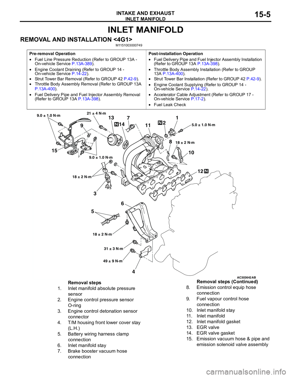
INLET MANIFOLD
INTAKE AND EXHAUST15-5
INLET MANIFOLD
REMOVAL AND INSTALLATION <4G1>M1151003000749
Pre-removal Operation
•Fuel Line Pressure Reduction (Refer to GROUP 13A -
On-vehicle Service P.13A-389).
•Engine Coolant Draining (Refer to GROUP 14 -
On-vehicle Service P.14-22).
•Strut Tower Bar Removal (Refer to GROUP 42 P.42-9).
•Throttle Body Assembly Removal (Refer to GROUP 13A
P.13A-400).
•Fuel Delivery Pipe and Fuel Injector Assembly Removal
(Refer to GROUP 13A P.13A-398).Post-installation Operation
•Fuel Delivery Pipe and Fuel Injector Assembly Installation
(Refer to GROUP 13A P.13A-398).
•Throttle Body Assembly Installation (Refer to GROUP
13A P.13A-400).
•Strut Tower Bar Installation (Refer to GROUP 42 P.42-9).
•Engine Coolant Supplying (Refer to GROUP 14 -
On-vehicle Service P.14-22).
•Accelerator Cable Adjustment (Refer to GROUP 17 -
On-vehicle Service P.17-2).
•Fuel Leak Check
AC303642AB
15
3
6
5
412 10 71
2
11
913
14
21 ± 4 N·m
9.0 ± 1.0 N·m
9.0 ± 1.0 N·m
18 ± 2 N·m
18 ± 2 N·m18 ± 2 N·m5.0 ± 1.0 N·m
31 ± 3 N·m
49 ± 9 N·m
N
N
N
8
Removal steps
1. Inlet manifold absolute pressure
sensor
2. Engine control pressure sensor
O-ring
3. Engine control detonation sensor
connector
4. T/M housing front lower cover stay
(L.H.)
5. Battery wiring harness clamp
connection
6. Inlet manifold stay
7. Brake booster vacuum hose
connection8. Emission control equip hose
connection
9. Fuel vapour control hose
connection
10. Inlet manifold stay
11. Inlet manifold
12. Inlet manifold gasket
13. EGR valve
14. EGR valve gasket
15. Emission vacuum hose & pipe and
emission solenoid valve assembly Removal steps (Continued)
Page 58 of 788
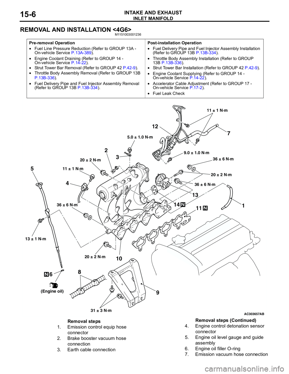
INLET MANIFOLD
INTAKE AND EXHAUST15-6
REMOVAL AND INSTALLATION <4G6>M1151003001236
Pre-removal Operation
•Fuel Line Pressure Reduction (Refer to GROUP 13A -
On-vehicle Service P.13A-389).
•Engine Coolant Draining (Refer to GROUP 14 -
On-vehicle Service P.14-22).
•Strut Tower Bar Removal (Refer to GROUP 42 P.42-9).
•Throttle Body Assembly Removal (Refer to GROUP 13B
P.13B-336).
•Fuel Delivery Pipe and Fuel Injector Assembly Removal
(Refer to GROUP 13B P.13B-334).Post-installation Operation
•Fuel Delivery Pipe and Fuel Injector Assembly Installation
(Refer to GROUP 13B P.13B-334).
•Throttle Body Assembly Installation (Refer to GROUP
13B P.13B-336).
•Strut Tower Bar Installation (Refer to GROUP 42 P.42-9).
•Engine Coolant Supplying (Refer to GROUP 14 -
On-vehicle Service P.14-22).
•Accelerator Cable Adjustment (Refer to GROUP 17 -
On-vehicle Service P.17-2).
•Fuel Leak Check
AC303657
9.0 ± 1.0 N·m11 ± 1 N·m
20 ± 2 N·m
31 ± 3 N·m 36 ± 6 N·m
20 ± 2 N·m
20 ± 2 N·m
36 ± 6 N·m
36 ± 6 N·m
11
9 10 212
N1413N
AB
5.0 ± 1.0 N·m
3
1
11 ± 1 N·m
4
N
13 ± 1 N·m
5
6
(Engine oil)
7
8
Removal steps
1. Emission control equip hose
connector
2. Brake booster vacuum hose
connection
3. Earth cable connection4. Engine control detonation sensor
connector
5. Engine oil level gauge and guide
assembly
6. Engine oil filler O-ring
7. Emission vacuum hose connectionRemoval steps (Continued)
Page 140 of 788
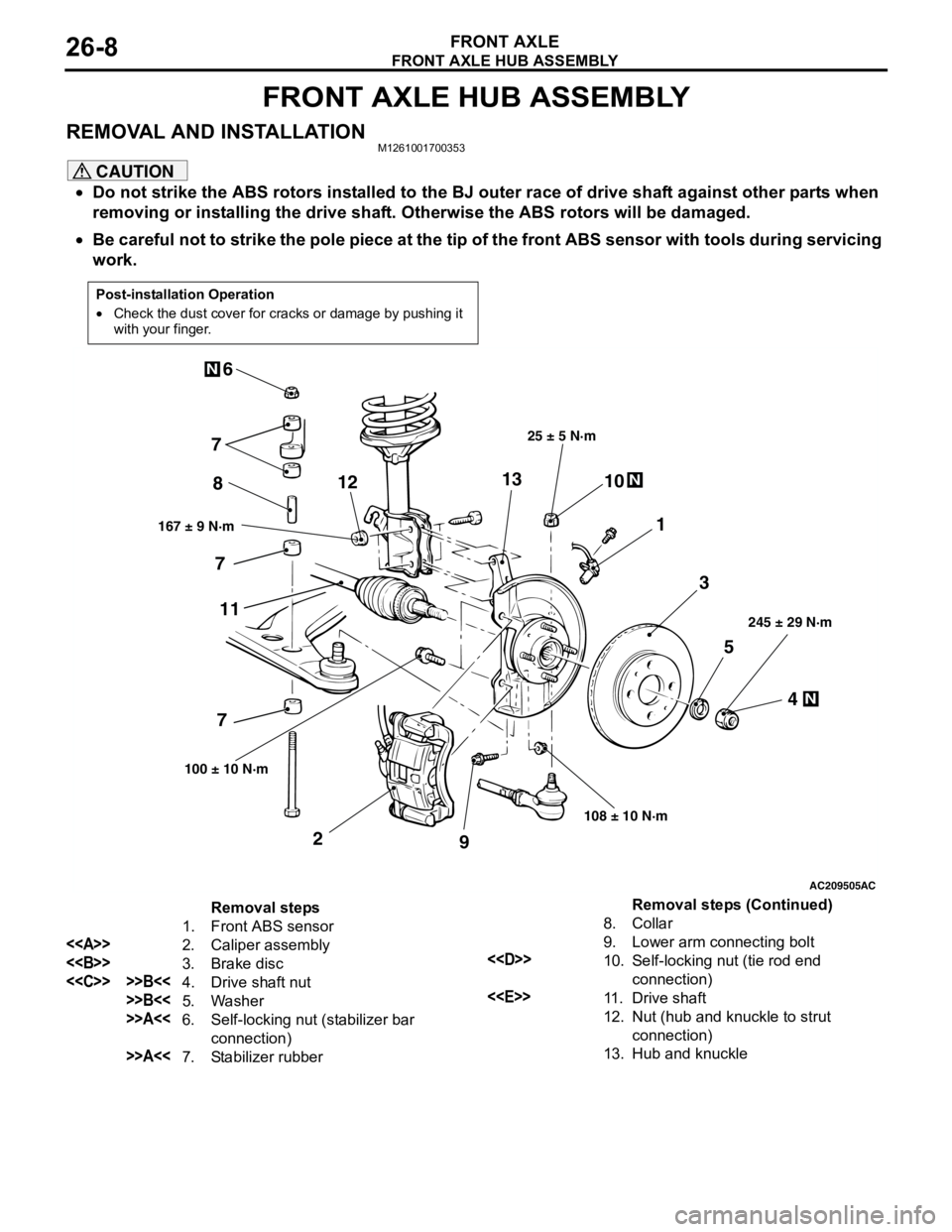
FRONT AXLE HUB ASSEMBLY
FRONT AXLE26-8
FRONT AXLE HUB ASSEMBLY
REMOVAL AND INSTALLATIONM1261001700353
CAUTION
•Do not strike the ABS rotors installed to the BJ outer race of drive shaft against other parts when
removing or installing the drive shaft. Otherwise the ABS rotors will be damaged.
•Be careful not to strike the pole piece at the tip of the front ABS sensor with tools during servicing
work.
Post-installation Operation
•Check the dust cover for cracks or damage by pushing it
with your finger.
AC209505
N
N
N
5
4 3 1 810
9 2 76
167 ± 9 N·m25 ± 5 N·m
108 ± 10 N·m245 ± 29 N·m
100 ± 10 N·m
AC
7
7
111213
Removal steps
1. Front ABS sensor
<>
2. Caliper assembly
<>
3. Brake disc
<
>>B<<5. Washer
>>A<<6. Self-locking nut (stabilizer bar
connection)
>>A<<7. Stabilizer rubber8. Collar
9. Lower arm connecting bolt
<
10. Self-locking nut (tie rod end
connection)
<
11 . D r i v e s h a f t
12. Nut (hub and knuckle to strut
connection)
13. Hub and knuckle
Removal steps (Continued)
Page 146 of 788
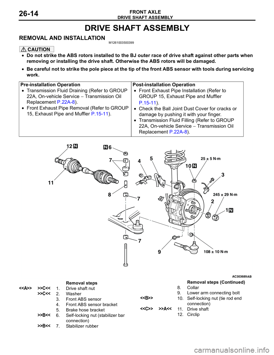
DRIVE SHAFT ASSEMBLY
FRONT AXLE26-14
DRIVE SHAFT ASSEMBLY
REMOVAL AND INSTALLATIONM1261003500399
CAUTION
•Do not strike the ABS rotors installed to the BJ outer race of drive shaft against other parts when
removing or installing the drive shaft. Otherwise the ABS rotors will be damaged.
•Be careful not to strike the pole piece at the tip of the front ABS sensor with tools during servicing
work.
Pre-installation Operation
•Transmission Fluid Draining (Refer to GROUP
22A, On-vehicle Service − Transmission Oil
Replacement P.22A-8).
•Front Exhaust Pipe Removal (Refer to GROUP
15, Exhaust Pipe and Muffler P.15-11).Post-installation Operation
•Front Exhaust Pipe Installation (Refer to
GROUP 15, Exhaust Pipe and Muffler
P.15-11).
•Check the Ball Joint Dust Cover for cracks or
damage by pushing it with your finger.
•Transmission Fluid Filling (Refer to GROUP
22A, On-vehicle Service − Transmission Oil
Replacement P.22A-8).
AC303689AB
9
N
N
NN
10 7
4
3
2
1
25 ± 5 N·m
245 ± 29 N·m
108 ± 10 N·m
8
5 6
1112
7
7
Removal steps
<> >>C<<1. Drive shaft nut
>>C<<2. Washer
3. Front ABS sensor
4. Front ABS sensor bracket
5. Brake hose bracket
>>B<<6. Self-locking nut (stabilizer bar
connection)
>>B<<7. Stabilizer rubber8. Collar
9. Lower arm connecting bolt
<>10. Self-locking nut (tie rod end
connection)
<
12. CirclipRemoval steps (Continued)
Page 189 of 788
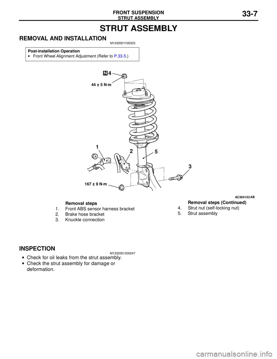
STRUT ASSEMBLY
FRONT SUSPENSION33-7
STRUT ASSEMBLY
REMOVAL AND INSTALLATIONM1332001100325
INSPECTIONM1332001200247
•Check for oil leaks from the strut assembly.
•Check the strut assembly for damage or
deformation.
Post-installation Operation
•Front Wheel Alignment Adjustment (Refer to P.33-5.)
AC304153
44 ± 5 N·m
1
2
3 4
N
AB
167 ± 9 N·m
5
Removal steps
1. Front ABS sensor harness bracket
2. Brake hose bracket
3. Knuckle connection4. Strut nut (self-locking nut)
5. Strut assemblyRemoval steps (Continued)
Page 212 of 788

TRAILING ARM ASSEMBLY
REAR SUSPENSION34-12
TRAILING ARM ASSEMBLY
REMOVAL AND INSTALLATIONM1341002200594
CAUTION
*: Indicates parts which should be temporarily tightened, and then fully tightened with the vehicle on
the earth in the unladen condition.
Pre-removal Operation
•Brake Fluid Draining
•Rear Hub Assembly Removal (Refer to GROUP 27, Rear
Axle Hub Assembly P.27-5).Post-installation Operation
•Rear Hub Assembly Installation (Refer to GROUP 27,
Rear Axle Hub Assembly P.27-5).
•Brake Fluid Supplying and Bleeding (Refer to GROUP
35A, On-vehicle Service − Bleeding P.35A-6).
•Rear Wheel Alignment Check and Adjustment (Refer to
P.34-5).
•Parking Brake Lever Stroke Adjustment (Refer to GROUP
36, On-vehicle Service − Parking Brake Lever Stroke
Check and Adjustment P.36-3).
AC101449
AC301223
AC304155AB
90 ± 10 N·m*
120 ± 10 N·m*
95 ± 15 N·m*63 ± 7 N·m
6 78
1 1011
23
4
120 ± 10 N·m*
15 ± 2 N·m
N
9
5
Removal steps
<>•Lifting point
1. Rear ABS Sensor (Refer to
GROUP 35B, ABS Sensor
P.35B-71).
2. Parking brake cable
3. Brake hose and trailing arm
connection
4. Rear parking brake assembly>>A<<5. Lower arm assembly and stabilizer
link connection
6. Lower arm assembly and shock
absorber connection
7. Control link and trailing arm
connection
8. Upper arm assembly and trailing
arm connection Removal steps (Continued)
Page 595 of 788
Page 614 of 788
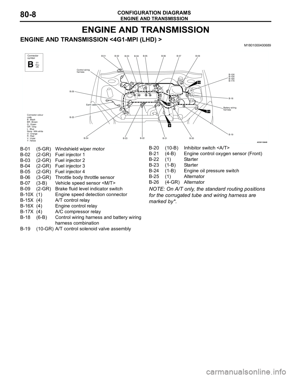
ENGINE AND TRANSMISSION
CONFIGURATION DIAGRAMS80-8
ENGINE AND TRANSMISSION
ENGINE AND TRANSMISSION <4G1-MPI (LHD) >M1801000400689
NOTE: On A/T only, the standard routing positions
for the corrugated tube and wiring harness are
marked by*.
AC301128
B-02
B-03B-04B-05
B-22
B-23 B-24 B-25 B-26Control wiring
harnessB-01
Connector colour
code
B : Black
BR : Brown
G : Green
GR : Gray
L : Blue
None : Milk white
O : Orange
R : Red
V : Violet
Y : Yellow*
Connector
symbol
-01
thru
-26B
Earth cable
AB
9
10
11
13
B-06B-07
B-09
B-10X
B-15X
B-16X
B-17X
B-18
Battery wiring
harness
B-19
B-20
B-21
*
B-01 (5-GR) Windshield wiper motor
B-02 (2-GR) Fuel injector 1
B-03 (2-GR) Fuel injector 2
B-04 (2-GR) Fuel injector 3
B-05 (2-GR) Fuel injector 4
B-06 (3-GR) Throttle body throttle sensor
B-07 (3-B) Vehicle speed sensor
B-09 (2-GR) Brake fluid level indicator switch
B-10X (1) Engine speed detection connector
B-15X (4) A/T control relay
B-16X (4) Engine control relay
B-17X (4) A/C compressor relay
B-18 (6-B) Control wiring harness and battery wiring
harness combination
B-19 (10-GR) A/T control solenoid valve assemblyB-20 (10-B) Inhibitor switch
B-21 (4-B) Engine control oxygen sensor (Front)
B-22 (1) Starter
B-23 (1-B) Starter
B-24 (1-B) Engine oil pressure switch
B-25 (1) Alternator
B-26 (4-GR) Alternator
Page 616 of 788
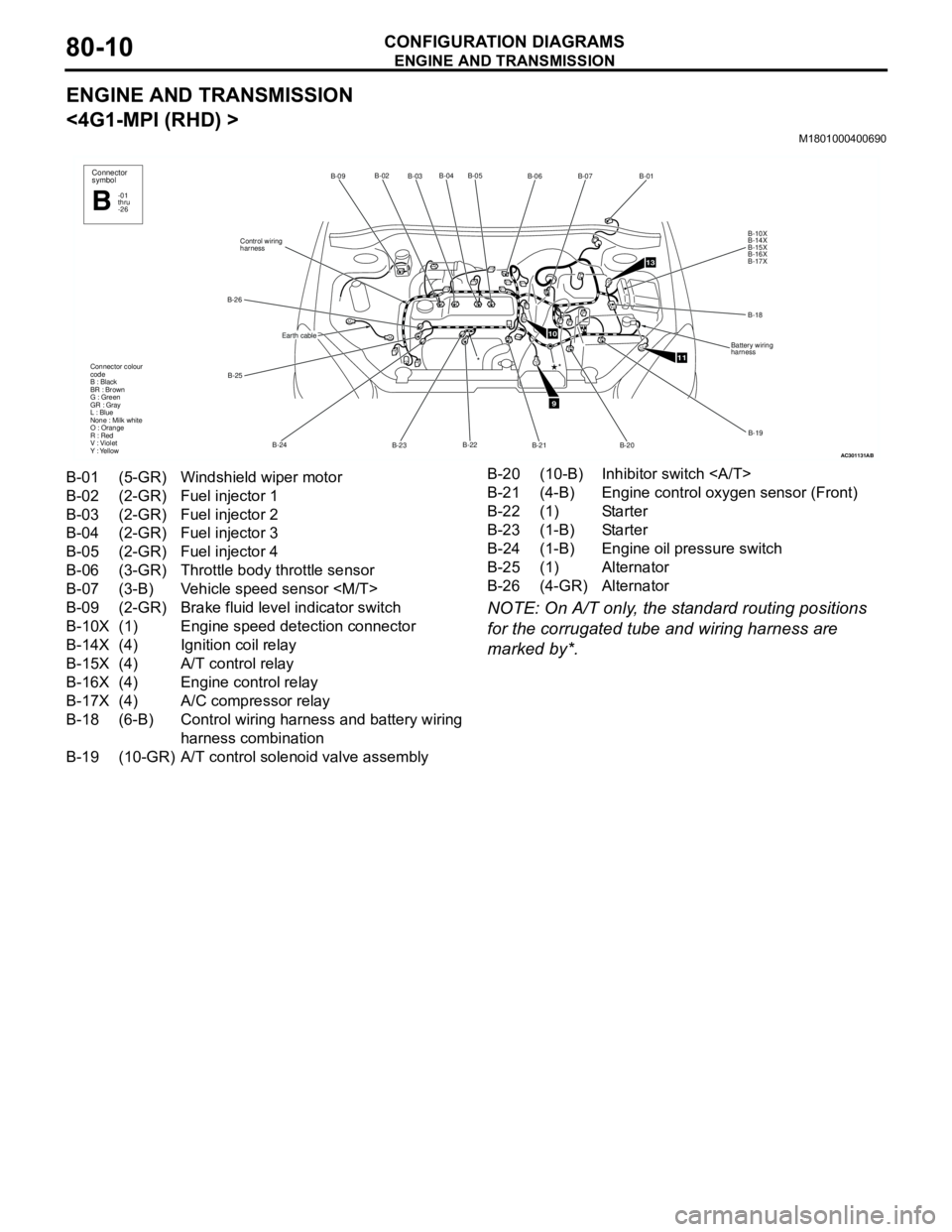
ENGINE AND TRANSMISSION
CONFIGURATION DIAGRAMS80-10
ENGINE AND TRANSMISSION
<4G1-MPI (RHD) >
M1801000400690
NOTE: On A/T only, the standard routing positions
for the corrugated tube and wiring harness are
marked by*.
AC301131
B-02
B-03B-04 B-05
B-22
B-23 B-24 B-25 B-26Control wiring
harnessB-09
Connector colour
code
B : Black
BR : Brown
G : Green
GR : Gray
L : Blue
None : Milk white
O : Orange
R : Red
V : Violet
Y : Yellow*
Connector
symbol
-01
thru
-26B
Earth cable
AB
9
10
11
13
B-06B-07
B-01
B-10X
B-14X
B-15X
B-16X
B-17X
B-18
Battery wiring
harness
B-19
B-20 B-21
*
B-01 (5-GR) Windshield wiper motor
B-02 (2-GR) Fuel injector 1
B-03 (2-GR) Fuel injector 2
B-04 (2-GR) Fuel injector 3
B-05 (2-GR) Fuel injector 4
B-06 (3-GR) Throttle body throttle sensor
B-07 (3-B) Vehicle speed sensor
B-09 (2-GR) Brake fluid level indicator switch
B-10X (1) Engine speed detection connector
B-14X (4) Ignition coil relay
B-15X (4) A/T control relay
B-16X (4) Engine control relay
B-17X (4) A/C compressor relay
B-18 (6-B) Control wiring harness and battery wiring
harness combination
B-19 (10-GR) A/T control solenoid valve assemblyB-20 (10-B) Inhibitor switch
B-21 (4-B) Engine control oxygen sensor (Front)
B-22 (1) Starter
B-23 (1-B) Starter
B-24 (1-B) Engine oil pressure switch
B-25 (1) Alternator
B-26 (4-GR) Alternator
Page 618 of 788
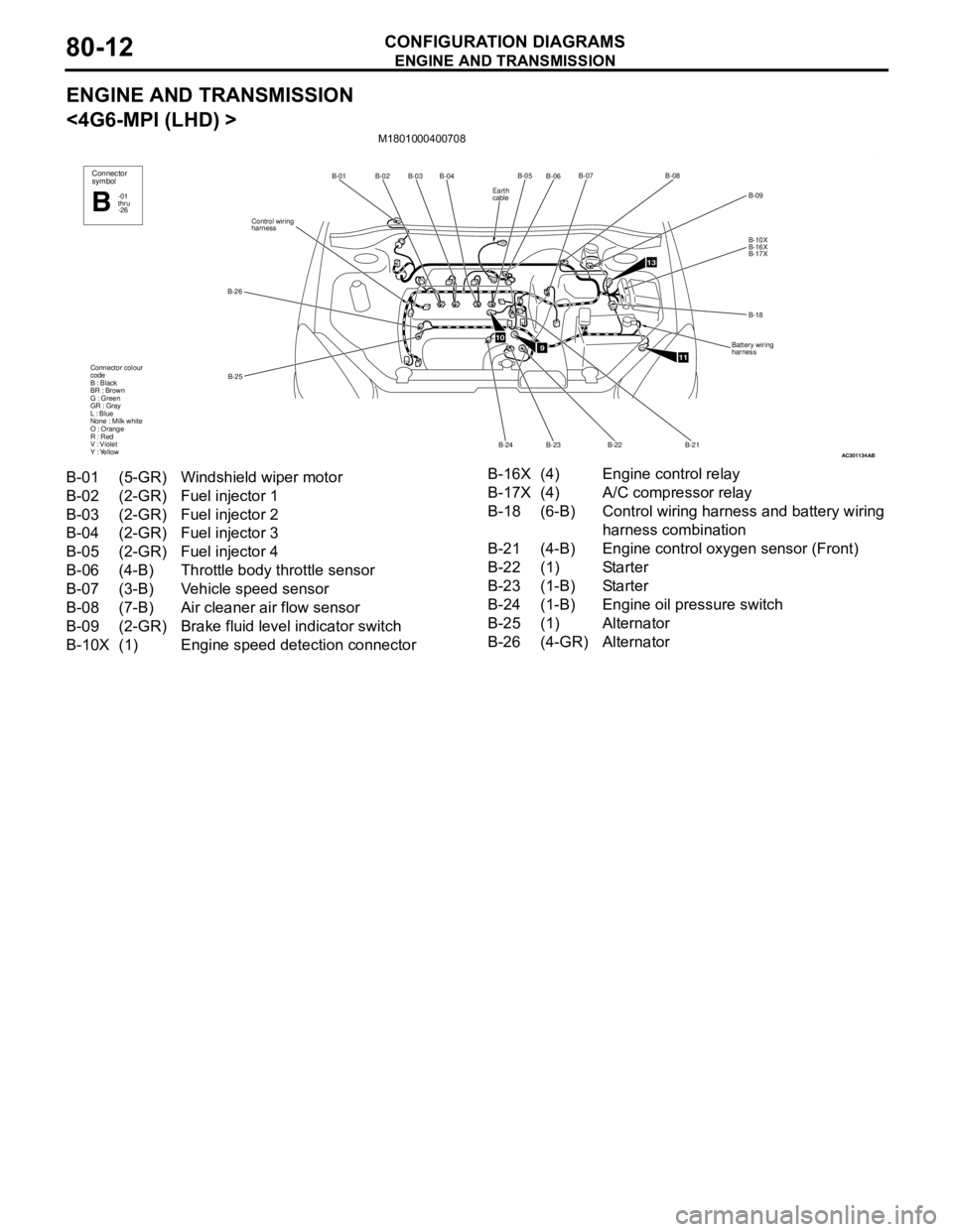
ENGINE AND TRANSMISSION
CONFIGURATION DIAGRAMS80-12
ENGINE AND TRANSMISSION
<4G6-MPI (LHD) >
M1801000400708
AC301134
B-02
B-03B-04
B-25 B-26Control wiring
harnessB-01
Connector colour
code
B : Black
BR : Brown
G : Green
GR : Gray
L : Blue
None : Milk white
O : Orange
R : Red
V : Violet
Y : YellowConnector
symbol
-01
thru
-26B
AB
910
11
13
B-06B-07
B-09
B-10X
B-16X
B-17X
B-18
Battery wiring
harness
B-21 B-22
B-23B-05B-08
B-24
Earth
cable
B-01 (5-GR) Windshield wiper motor
B-02 (2-GR) Fuel injector 1
B-03 (2-GR) Fuel injector 2
B-04 (2-GR) Fuel injector 3
B-05 (2-GR) Fuel injector 4
B-06 (4-B) Throttle body throttle sensor
B-07 (3-B) Vehicle speed sensor
B-08 (7-B) Air cleaner air flow sensor
B-09 (2-GR) Brake fluid level indicator switch
B-10X (1) Engine speed detection connectorB-16X (4) Engine control relay
B-17X (4) A/C compressor relay
B-18 (6-B) Control wiring harness and battery wiring
harness combination
B-21 (4-B) Engine control oxygen sensor (Front)
B-22 (1) Starter
B-23 (1-B) Starter
B-24 (1-B) Engine oil pressure switch
B-25 (1) Alternator
B-26 (4-GR) Alternator