fog light MITSUBISHI LANCER 2005 Workshop Manual
[x] Cancel search | Manufacturer: MITSUBISHI, Model Year: 2005, Model line: LANCER, Model: MITSUBISHI LANCER 2005Pages: 788, PDF Size: 45.98 MB
Page 375 of 788
DOOR MIRROR
EXTERIOR51-37
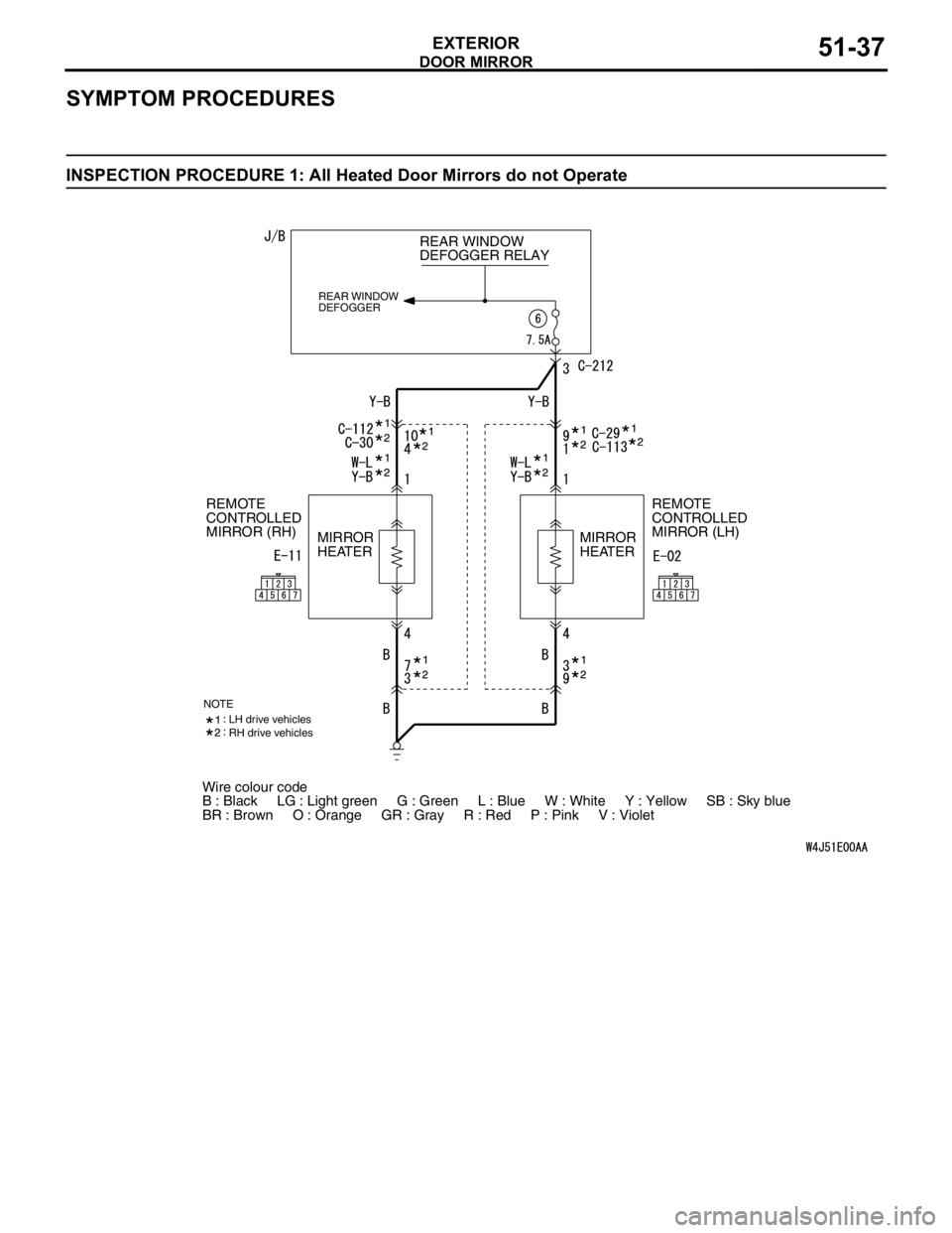
SYMPTOM PROCEDURES
INSPECTION PROCEDURE 1: All Heated Door Mirrors do not Operate
Wire colour code
B : Black LG : Light green G : Green L : Blue W : White Y : Yellow SB : Sky blue
BR : Brown O : Orange GR : Gray R : Red P : Pink V : Violet REAR WINDOW
DEFOGGER RELAY
REAR WINDOW
DEFOGGER
REMOTE
CONTROLLED
MIRROR (LH) REMOTE
CONTROLLED
MIRROR (RH)
MIRROR
HEATERMIRROR
HEATER
NOTELH drive vehicles
RH drive vehicles
Page 377 of 788
DOOR MIRROR
EXTERIOR51-39
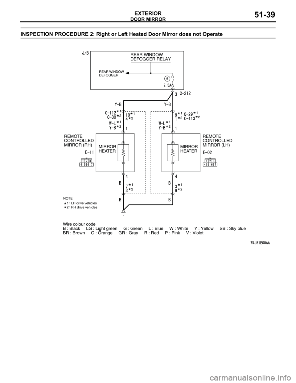
INSPECTION PROCEDURE 2: Right or Left Heated Door Mirror does not Operate
Wire colour code
B : Black LG : Light green G : Green L : Blue W : White Y : Yellow SB : Sky blue
BR : Brown O : Orange GR : Gray R : Red P : Pink V : Violet REAR WINDOW
DEFOGGER RELAY
REAR WINDOW
DEFOGGER
REMOTE
CONTROLLED
MIRROR (LH) REMOTE
CONTROLLED
MIRROR (RH)
MIRROR
HEATERMIRROR
HEATER
NOTELH drive vehicles
RH drive vehicles
Page 391 of 788

54A-3
REAR COMBINATION
LAMP . . . . . . . . . . . . . . . . . . . . .
54A-79
TROUBLESHOOTING . . . . . . . . . .
54A-79
SPECIAL TOOL . . . . . . . . . . . . . . .54A-79
REAR COMBINATION LAMP . . . .54A-79
REMOVAL AND INSTALLATION . . . . . 54A-79
HIGH-MOUNTED
STOP LAMP. . . . . . . . . . . . . . . .
54A-80
ON-VEHICLE SERVICE. . . . . . . . .
54A-80
HIGH-MOUNTED STOP LAMP BULB
REPLACEMENT
HIGH-MOUNTED STOP LAMP . . .54A-81
REMOVAL AND INSTALLATION . . . . . 54A-81
LICENCE PLATE LAMP . . . . . .54A-84
REMOVAL AND INSTALLATION .
54A-84
HAZARD WARNING LAMP
SWITCH . . . . . . . . . . . . . . . . . . .
54A-85
TROUBLESHOOTING . . . . . . . . . .
54A-85
SPECIAL TOOL . . . . . . . . . . . . . . .54A-85
HAZARD WARNING LAMP SWITCH54A-86
REMOVAL AND INSTALLATION . . . . . 54A-86
INSPECTION . . . . . . . . . . . . . . . . . . . . . 54A-86
COLUMN SWITCH. . . . . . . . . . .54A-87
SPECIAL TOOL . . . . . . . . . . . . . . .
54A-87
COLUMN SWITCH. . . . . . . . . . . . .54A-87
REMOVAL AND INSTALLATION . . . . . 54A-87
INSPECTION . . . . . . . . . . . . . . . . . . . . . 54A-88
HORN . . . . . . . . . . . . . . . . . . . . 54A-89
REMOVAL AND INSTALLATION . . . . . . 54A-89
HORN RELAY CONTINUITY CHECK . . 54A-89
CLOCK . . . . . . . . . . . . . . . . . . . 54A-90
SPECIAL TOOL . . . . . . . . . . . . . . .
54A-90
CLOCK . . . . . . . . . . . . . . . . . . . . . .54A-90
REMOVAL AND INSTALLATION . . . . . . 54A-90
CIGARETTE LIGHTER . . . . . . 54A-91
INSPECTION . . . . . . . . . . . . . . . . . . . . . 54A-91
RHEOSTAT . . . . . . . . . . . . . . . 54A-91
REMOVAL AND INSTALLATION . . . . . . 54A-91
INSPECTION . . . . . . . . . . . . . . . . . . . . . 54A-92
SPEAKER. . . . . . . . . . . . . . . . . 54A-93
REMOVAL AND INSTALLATION . . . . . . 54A-93
ANTENNA . . . . . . . . . . . . . . . . 54A-94
REMOVAL AND INSTALLATION . . . . . . 54A-94
REAR WINDOW
DEFOGGER . . . . . . . . . . . . . . .
54A-95
GENERAL INFORMATION . . . . . .
54A-95
TROUBLESHOOTING . . . . . . . . . .54A-95
ON-VEHICLE SERVICE . . . . . . . . .54A-96
PRINTED HEATER LINES CHECK . . . . 54A-96
REAR WINDOW DEFOGGER
SWITCH . . . . . . . . . . . . . . . . . . . . .
54A-96
REMOVAL AND INSTALLATION . . . . . . 54A-96
INSPECTION . . . . . . . . . . . . . . . . . . . . . 54A-96
Page 459 of 788
FOG LAMP
CHASSIS ELECTRICAL54A-71
FOG LAMP
SERVICE SPECIFICATIONM1542000300343
SPECIAL TOOLM1542000600894
TROUBLESHOOTINGM1542000701292
When the front fog lamp switch is turned to ON with
the tail lamp or the headlamp on (the tail lamp switch
or the headlamp switch is ON), the fog lamp relay
turns on, and the fog lamps will illuminate.
If the tail lamps or the headlamps are turned off with
the lighting switch OFF while the fog lamps are on,
the front fog lamps turn off at the same time to
prevent unattended operation.
If the tail lamps are turned off by the headlamp
automatic shutdown function, the fog lamps turn off
at the same time. However, if the tail lamps illuminate
again, the fog lamps do not.
The front fog lamps are controlled by the Smart
Wiring System (SWS). For troubleshooting, refer to
respective Groups below.
•Not using SWS monitor: GROUP 54B, SWS
Troubleshooting P.54B-38.
•Using SWS monitor: GROUP 54C, SWS
Troubleshooting P.54C-22.
ON-VEHICLE SERVICE
FRONT FOG LAMP AIMING CHECKM1542001100438
After setting the vehicles to the following condition,
adjust the front fog lamp aiming.
•Check that the tyre inflation pressure is at the
value indicated on the tyre pressure labels.
•Set the vehicle to the unladen condition and park
it on a level surface.
•Have a single person (approximately 75 kg) sit in
the driver’s seat.•Run the engine at a speed of 2000 r/min to fully
charge the battery.
Turn on the front fog lamps and check that the
illumination is within the standard value range.
Standard value: Illuminates to within 40
metres
CAUTION
For the fog lamp which is not being measured,
disconnect that fog lamp’s connector if possible
so that it does not illuminate while carrying out
the adjustment. Furthermore, make sure that the
light axis does not get shifted when
re-connecting the connector.
If the value is out of the standard value, insert the
screwdriver (+) through the aiming hole on the side
under cover to adjust by turning the adjusting gear
for fog lamp aiming.
NOTE: Horizontal adjustment is not possible.
In addition, the method of checking the light axis on a
screen (simple check) is given below. Item Standard value
Front fog lamp light axis check Illuminates to within 40 metres
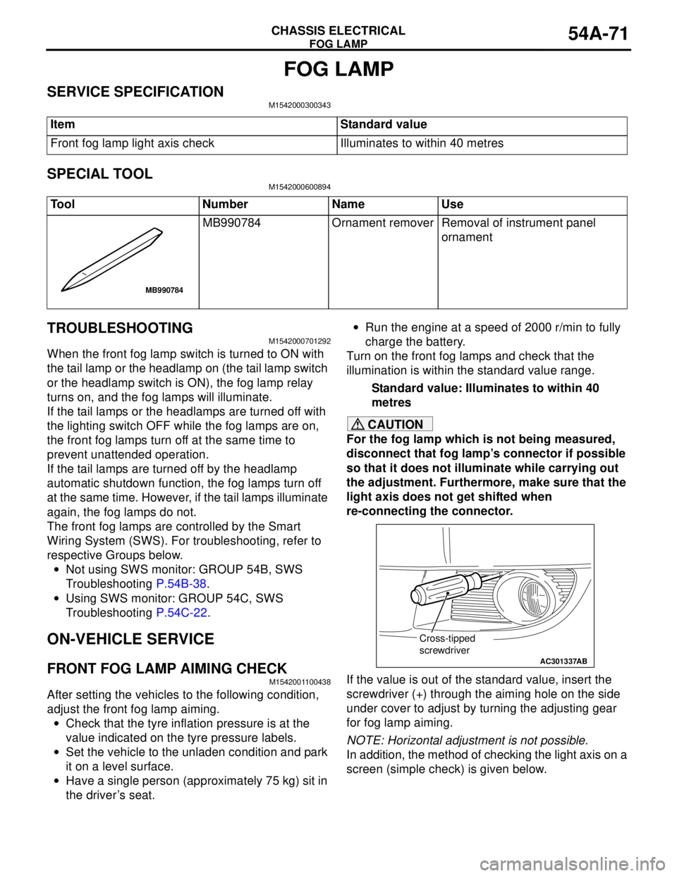
Tool Number Name Use
MB990784 Ornament remover Removal of instrument panel
ornament
MB990784
AC301337
Cross-tipped
screwdriver
AB
Page 460 of 788
FOG LAMP
CHASSIS ELECTRICAL54A-72
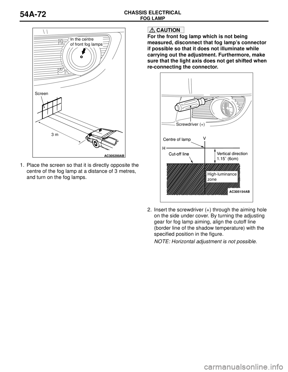
1. Place the screen so that it is directly opposite the
centre of the fog lamp at a distance of 3 metres,
and turn on the fog lamps.
CAUTION
For the front fog lamp which is not being
measured, disconnect that fog lamp’s connector
if possible so that it does not illuminate while
carrying out the adjustment. Furthermore, make
sure that the light axis does not get shifted when
re-connecting the connector.
2. Insert the screwdriver (+) through the aiming hole
on the side under cover. By turning the adjusting
gear for fog lamp aiming, align the cutoff line
(border line of the shadow temperature) with the
specified position in the figure.
NOTE: Horizontal adjustment is not possible.
AC305200AB
In the centre
of front fog lamps
Screen
3 m
H V
AC305154
Screwdriver (+)
Centre of lamp
Cut-off lineVertical direction
1.15˚ (6cm)
High-luminance
zone H V
Screwdriver (+)
Centre of lamp
Cut-off lineVertical direction
1.15˚ (6cm)
High-luminance
zone
AB
Page 526 of 788
TROUBLESHOOTING
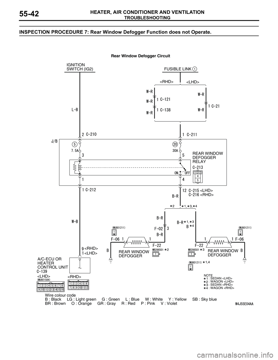
HEATER, AIR CONDITIONER AND VENTILATION55-42
INSPECTION PROCEDURE 7: Rear Window Defogger Function does not Operate.
IGNITION
SWITCH (IG2) FUSIBLE LINK
REAR WINDOW
DEFOGGER
RELAY
A/C-ECU OR
HEATER
CONTROL UNIT1
: SEDAN
: WAGON
: SEDAN
: WAGON
Wire colour code
B : Black LG : Light green G : Green L : Blue W : White Y : Yellow SB : Sky blue
BR : Brown O : Orange GR : Gray R : Red P : Pink V : Violet
NOTE
REAR WINDOW
DEFOGGERREAR WINDOW
DEFOGGER Rear Window Defogger Circuit
Page 537 of 788
TROUBLESHOOTING
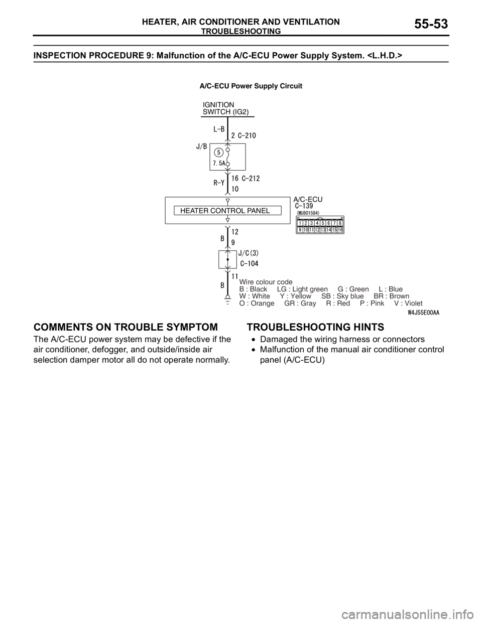
HEATER, AIR CONDITIONER AND VENTILATION55-53
INSPECTION PROCEDURE 9: Malfunction of the A/C-ECU Power Supply System.
COMMENTS ON TROUBLE SYMPTOM
The A/C-ECU power system may be defective if the
air conditioner, defogger, and outside/inside air
selection damper motor all do not operate normally.
TROUBLESHOOTING HINTS
•Damaged the wiring harness or connectors
•Malfunction of the manual air conditioner control
panel (A/C-ECU)
IGNITION
SWITCH (IG2)
A/C-ECU
Wire colour code
B : Black LG : Light green G : Green L : Blue
W : White Y : Yellow SB : Sky blue BR : Brown
O : Orange GR : Gray R : Red P : Pink V : Violet HEATER CONTROL PANEL
A/C-ECU Power Supply Circuit
Page 540 of 788
TROUBLESHOOTING
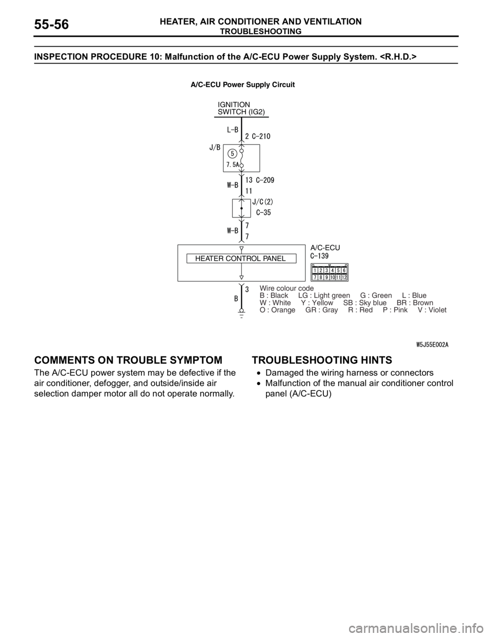
HEATER, AIR CONDITIONER AND VENTILATION55-56
INSPECTION PROCEDURE 10: Malfunction of the A/C-ECU Power Supply System.
COMMENTS ON TROUBLE SYMPTOM
The A/C-ECU power system may be defective if the
air conditioner, defogger, and outside/inside air
selection damper motor all do not operate normally.
TROUBLESHOOTING HINTS
•Damaged the wiring harness or connectors
•Malfunction of the manual air conditioner control
panel (A/C-ECU)
IGNITION
SWITCH (IG2)
HEATER CONTROL PANELA/C-ECU
Wire colour code
B : Black LG : Light green G : Green L : Blue
W : White Y : Yellow SB : Sky blue BR : Brown
O : Orange GR : Gray R : Red P : Pink V : Violet
A/C-ECU Power Supply Circuit
Page 551 of 788

TROUBLESHOOTING
HEATER, AIR CONDITIONER AND VENTILATION55-67
CHECK AT ECU TERMINAL
12
345
678
9 10111213141516
AC300861AC
Terminal No. Check item Checking requirement Normal condition
1 Rear defogger switch Defogger switch: ON 0 V
Defogger switch: OFF System voltage
2 Inside/outside air selection
damper motor (outside air)When the damper is moved to
the inside air recirculation
position0 V
When the damper is moved to
the outside air inside air intake
positionSystem voltage
3 Inside/outside air selection
damper motor (inside air)When the damper is moved to
the inside air recirculation
positionSystem voltage
When the damper is moved to
the outside air inside air intake
position0 V
4 Output to the engine-A/T-ECU
(A/C1)A/C stopped 0 V
•A/C switch: ON
•Blower switch: ONSystem voltage
5 Output to the engine-A/T-ECU
(A/C2)When the A/C is under low load System voltage
When the A/C is under high
load0 V
6 Power supply to the A/C
illuminationLighting switch: ON System voltage
7---
8 Blower switch (lo) blower switch: lo System voltage
9---
10 Power supply to the ignition
switch (IG2)Ignition switch: ON System voltage
11 Earth to the A/C illumination Always 0 V
12 Earth Always 0 V
13 Air thermo sensor (outlet side) Sensor probe temperature 25°C
(1.5k ohm)2.2 V
14, 15 - - -
16 Earth to the air thermo sensor Always 0 V
Page 552 of 788

TROUBLESHOOTING
HEATER, AIR CONDITIONER AND VENTILATION55-68
CHECK AT ECU TERMINAL
21
78
6 534
11
10912
AC304990
AB
Terminal No. Check item Checking requirement Normal condition
1 Output to the engine-A/T-ECU
(A/C1)A/C stopped 0 V
•A/C switch: ON
•Blower switch: ONSystem voltage
2 Output to the engine-A/T-ECU
(A/C2)When the A/C is under low load System voltage
When the A/C is under high
load0 V
3 Earth Always 0 V
4 Earth to the air thermo sensor Always 0 V
5 Power supply to the A/C
illuminationLighting switch: ON System voltage
6 Air thermo sensor (outlet side) Sensor probe temperature 25°C
(1.5k ohm)2.2 V
7 Power supply to the ignition
switch (IG2)Ignition switch: ON System voltage
8 Blower switch (lo) blower switch: lo System voltage
9 Rear defogger switch Defogger switch: ON 0 V
Defogger switch: OFF System voltage
10 Inside/outside air selection
damper motor (outside air)When the damper is moved to
the inside air recirculation
position0 V
When the damper is moved to
the outside air inside air intake
positionSystem voltage
11 Inside/outside air selection
damper motor (inside air)When the damper is moved to
the inside air recirculation
positionSystem voltage
When the damper is moved to
the outside air inside air intake
position0 V
12 Earth to the A/C illumination Always 0 V