height adjustment MITSUBISHI LANCER 2005 Workshop Manual
[x] Cancel search | Manufacturer: MITSUBISHI, Model Year: 2005, Model line: LANCER, Model: MITSUBISHI LANCER 2005Pages: 788, PDF Size: 45.98 MB
Page 279 of 788
42-1
GROUP 42
BODY
CONTENTS
HOOD . . . . . . . . . . . . . . . . . . . . .
42-3
ON-VEHICLE SERVICE. . . . . . . . .
42-3
ADJUSTMENT OF CLEARANCE
AROUND HOOD . . . . . . . . . . . . . . . . . . 42-3
ADJUSTMENT OF ALIGNMENT OF
HOOD STEPPED PORTION AND
HOOD STRIKER . . . . . . . . . . . . . . . . . . 42-3
ADJUSTMENT OF HOOD HEIGHT . . . 42-3
HOOD . . . . . . . . . . . . . . . . . . . . . . .42-4
REMOVAL AND INSTALLATION . . . . . 42-4
FENDER . . . . . . . . . . . . . . . . . . .42-5
SPECIAL TOOL . . . . . . . . . . . . . . .
42-5
FENDER . . . . . . . . . . . . . . . . . . . . .42-6
REMOVAL AND INSTALLATION . . . . . 42-6
FUEL FILLER LID . . . . . . . . . . .42-8
REMOVAL AND INSTALLATION .
42-8
STRUT TOWER BAR . . . . . . . .42-9
REMOVAL AND INSTALLATION .
42-9
WINDOW GLASS . . . . . . . . . . . 42-9
ADHESIVE . . . . . . . . . . . . . . . . . . .
42-9
SPECIAL TOOLS . . . . . . . . . . . . . .42-9
WINDOW REPAIR . . . . . . . . . . . . .42-10
WINDSHIELD . . . . . . . . . . . . . . . . .42-12
REMOVAL AND INSTALLATION . . . . . . 42-12
REAR WINDOW GLASS . . . . . . . .42-16
REMOVAL AND INSTALLATION . . . . . . 42-16
QUARTER WINDOW GLASS . . . .42-19
REMOVAL AND INSTALLATION . . . . . . 42-19
TAILGATE WINDOW GLASS . . . .42-22
REMOVAL AND INSTALLATION . . . . . . 42-22
DOOR . . . . . . . . . . . . . . . . . . . . 42-25
SERVICE SPECIFICATIONS . . . . .
42-25
SEALANT . . . . . . . . . . . . . . . . . . . .42-25
SPECIAL TOOLS . . . . . . . . . . . . . .42-25
Continued on next page
Page 280 of 788
42-2
TROUBLESHOOTING . . . . . . . . . .42-26
ON-VEHICLE SERVICE. . . . . . . . .42-27
DOOR FIT ADJUSTMENT. . . . . . . . . . . 42-27
DOOR WINDOW GLASS ADJUSTMENT42-28
GLASS SLIDING MECHANISM CHECK
AND ADJUSTMENT . . . . . . . . . . . . . . . 42-28
POWER WINDOW OPERATING
CURRENT CHECK . . . . . . . . . . . . . . . . 42-28
POWER WINDOW RELAY CHECK . . . 42-29
CIRCUIT BREAKER (INCORPORATED
IN THE POWER WINDOW MOTOR)
INSPECTION . . . . . . . . . . . . . . . . . . . . . 42-29
POWER WINDOW CHECK . . . . . . . . . . 42-29
CENTRAL DOOR LOCKING SYSTEM
INSPECTION . . . . . . . . . . . . . . . . . . . . . 42-29
DOOR OUTSIDE HANDLE PLAY
CHECK . . . . . . . . . . . . . . . . . . . . . . . . . 42-29
DOOR INSIDE HANDLE PLAY
ADJUSTMENT . . . . . . . . . . . . . . . . . . . . 42-30
DOOR ASSEMBLY . . . . . . . . . . . .42-31
REMOVAL AND INSTALLATION . . . . . 42-31
INSPECTION . . . . . . . . . . . . . . . . . . . . . 42-32
DOOR GLASS AND
REGULATOR . . . . . . . . . . . . . . . . .
42-32
REMOVAL AND INSTALLATION . . . . . 42-32
INSPECTION . . . . . . . . . . . . . . . . . . . . . 42-34
DOOR HANDLE AND LATCH . . . .42-36
REMOVAL AND INSTALLATION . . . . . 42-36
INSPECTION . . . . . . . . . . . . . . . . . . . . . 42-37
WINDOW GLASS RUNCHANNEL AND
DOOR OPENING
WEATHERSTRIP . . . . . . . . . . . . . .
42-39
REMOVAL AND INSTALLATION . . . . . 42-39
TRUNK LID . . . . . . . . . . . . . . . .42-41
SPECIAL TOOL . . . . . . . . . . . . . . .
42-41
ON-VEHICLE SERVICE. . . . . . . . .42-41
TRUNK LID ADJUSTMENT . . . . . . . . . . 42-41
ADJUSTMENT OF CLEARANCE
AROUND TRUNK LID . . . . . . . . . . . . . . 42-42
TRUNK LID STRIKER ADJUSTMENT . 42-42
TRUNK LID HEIGHT ADJUSTMENT . . 42-42
TRUNK LID . . . . . . . . . . . . . . . . . . .42-43
REMOVAL AND INSTALLATION . . . . . . 42-43
INSPECTION . . . . . . . . . . . . . . . . . . . . . 42-45
TAILGATE . . . . . . . . . . . . . . . . 42-46
SERVICE SPECIFICATIONS . . . . .
42-46
SEALANTS . . . . . . . . . . . . . . . . . . .42-46
SPECIAL TOOL . . . . . . . . . . . . . . .42-46
TROUBLESHOOTING . . . . . . . . . .42-46
ON-VEHICLE SERVICE . . . . . . . . .42-46
TAILGATE FIT ADJUSTMENT. . . . . . . . 42-46
TAILGATE HANDLE PLAY CHECK . . . . 42-47
TAILGATE . . . . . . . . . . . . . . . . . . .42-48
REMOVAL AND INSTALLATION . . . . . . 42-48
TAILGATE HANDLE AND
LATCH . . . . . . . . . . . . . . . . . . . . . .
42-50
REMOVAL AND INSTALLATION . . . . . . 42-50
INSPECTION . . . . . . . . . . . . . . . . . . . . . 42-51
KEYLESS ENTRY SYSTEM . . 42-51
SERVICE SPECIFICATIONS . . . . .
42-51
SPECIAL TOOLS . . . . . . . . . . . . . .42-52
TROUBLESHOOTING . . . . . . . . . .42-53
ON-VEHICLE SERVICE . . . . . . . . .42-53
KEYLESS ENTRY SYSTEM CHECK. . . 42-53
KEYLESS ENTRY SYSTEM TIMER
LOCK FUNCTION INSPECTION . . . . . . 42-53
ENABLING/DISABLING
THE ANSWERBACK FUNCTION . . . . . 42-53
HOW TO REGISTER SECRET CODE . 42-55
TRANSMITTER. . . . . . . . . . . . . . . .42-58
DISASSEMBLY AND REASSEMBLY . . 42-58
INSPECTION . . . . . . . . . . . . . . . . . . . . . 42-59
Page 281 of 788
HOOD
BODY42-3
HOOD
ON-VEHICLE SERVICE
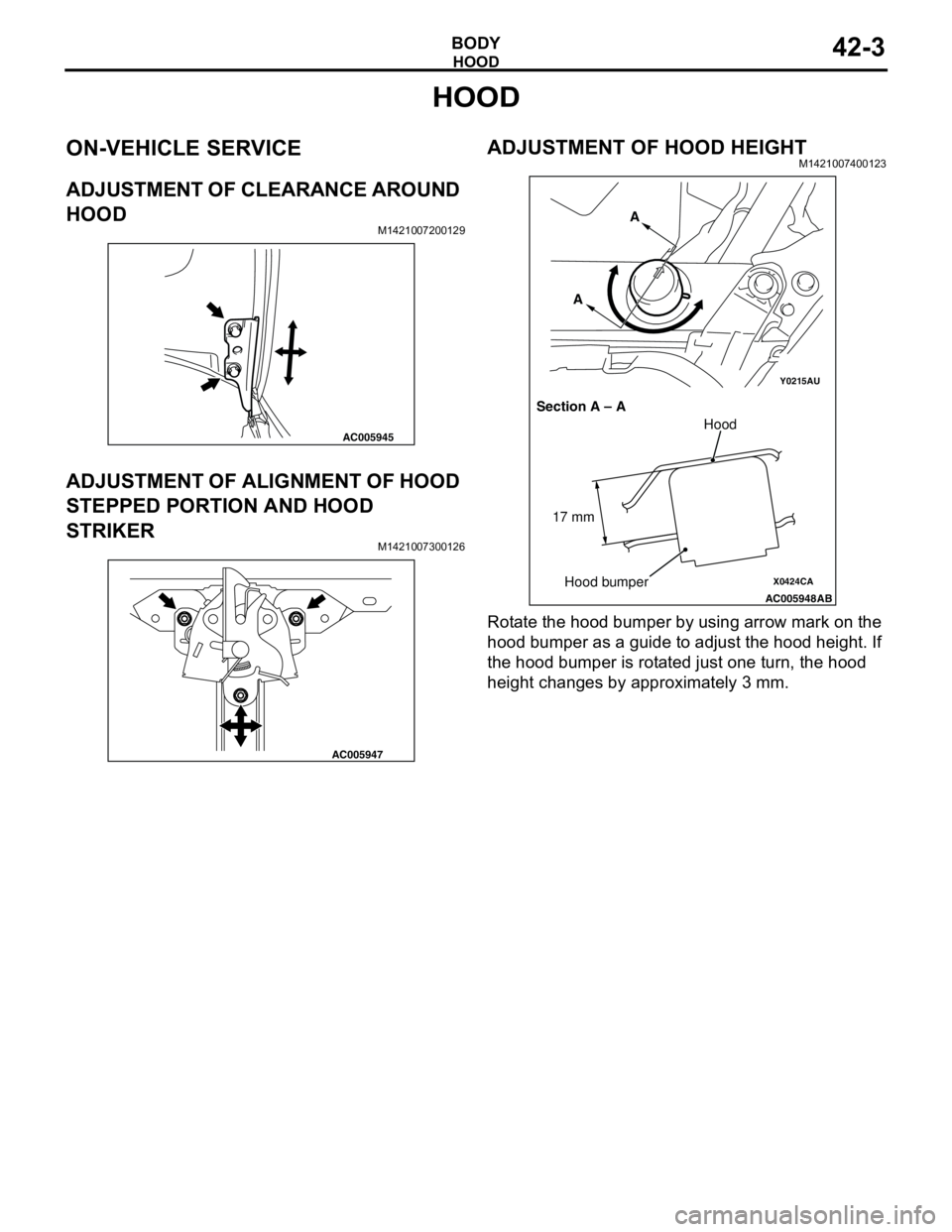
ADJUSTMENT OF CLEARANCE AROUND
HOOD
M1421007200129
ADJUSTMENT OF ALIGNMENT OF HOOD
STEPPED PORTION AND HOOD
STRIKER
M1421007300126
ADJUSTMENT OF HOOD HEIGHTM1421007400123
Rotate the hood bumper by using arrow mark on the
hood bumper as a guide to adjust the hood height. If
the hood bumper is rotated just one turn, the hood
height changes by approximately 3 mm.
AC005945
AC005947
Y0215AU
X0424CA
AC005948
AB
Section A – AA
A
Hood
Hood bumper 17 mm
Page 282 of 788
HOOD
BODY42-4
HOOD
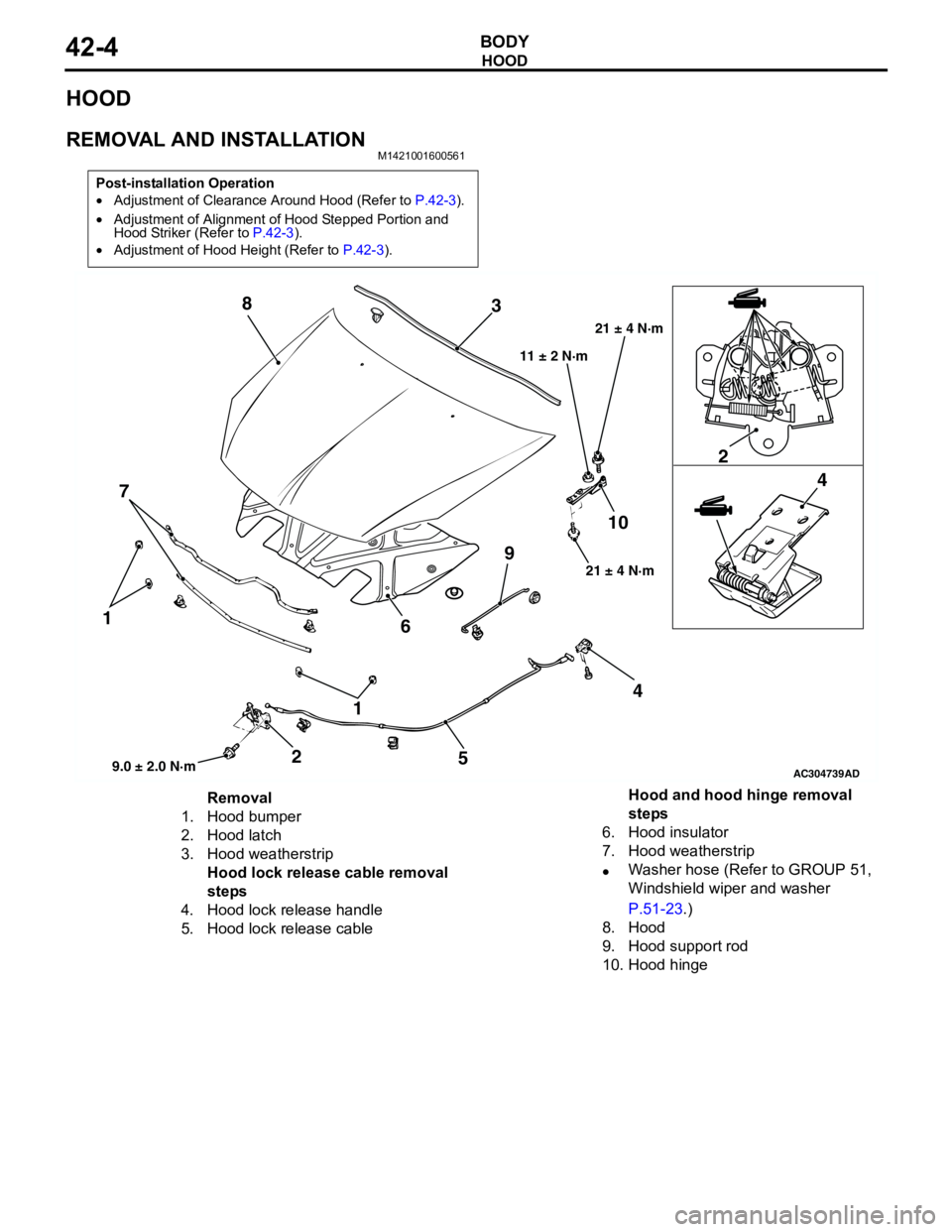
REMOVAL AND INSTALLATIONM1421001600561
Post-installation Operation
•Adjustment of Clearance Around Hood (Refer to P.42-3).
•Adjustment of Alignment of Hood Stepped Portion and
Hood Striker (Refer to P.42-3).
•Adjustment of Hood Height (Refer to P.42-3).
AC304739
1 1
22
44
5 6 73 8
910
AD9.0 ± 2.0 N·m21 ± 4 N·m 11 ± 2 N·m21 ± 4 N·m
Removal
1. Hood bumper
2. Hood latch
3. Hood weatherstrip
Hood lock release cable removal
steps
4. Hood lock release handle
5. Hood lock release cableHood and hood hinge removal
steps
6. Hood insulator
7. Hood weatherstrip
•Washer hose (Refer to GROUP 51,
Windshield wiper and washer
P.51-23.)
8. Hood
9. Hood support rod
10. Hood hinge
Page 286 of 788
FUEL FILLER LID
BODY42-8
FUEL FILLER LID
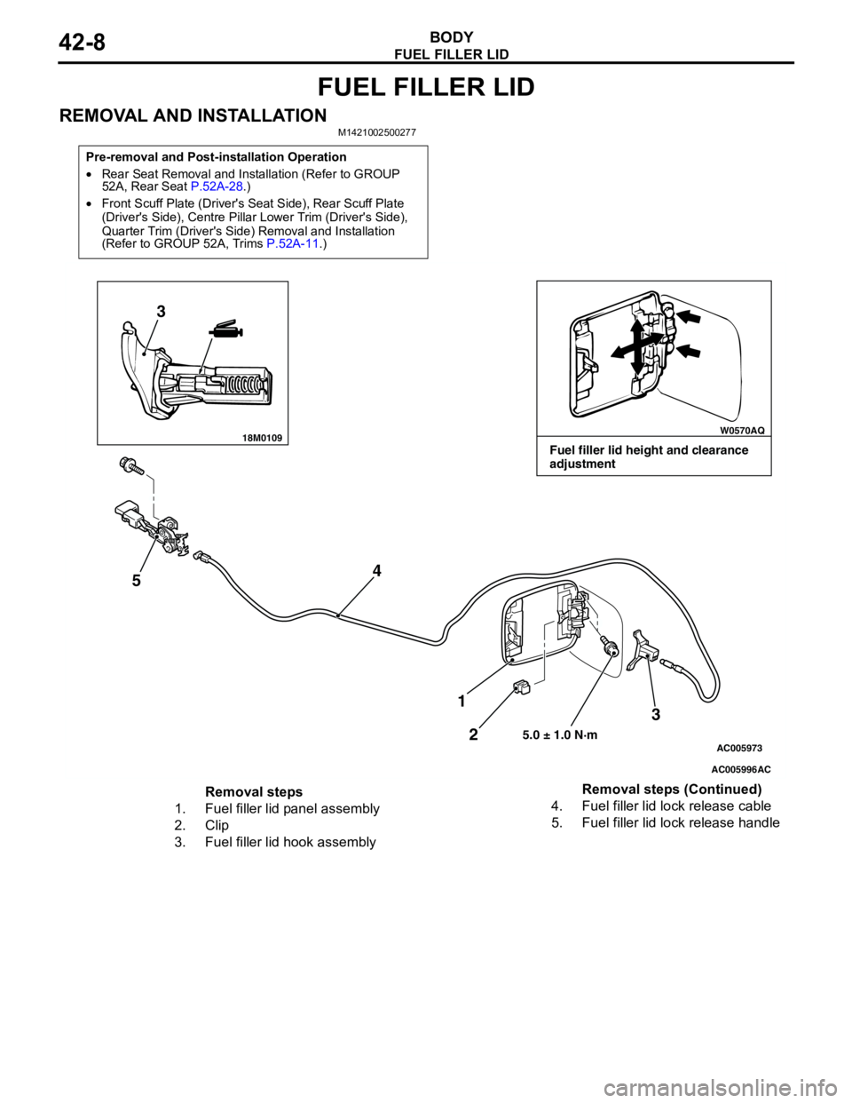
REMOVAL AND INSTALLATIONM1421002500277
Pre-removal and Post-installation Operation
•Rear Seat Removal and Installation (Refer to GROUP
52A, Rear Seat P.52A-28.)
•Front Scuff Plate (Driver's Seat Side), Rear Scuff Plate
(Driver's Side), Centre Pillar Lower Trim (Driver's Side),
Quarter Trim (Driver's Side) Removal and Installation
(Refer to GROUP 52A, Trims P.52A-11.)
18M0109W0570AQ
AC005996
AC005973
3
54
3
2 1
5.0 ± 1.0 N·m
AC
Fuel filler lid height and clearance
adjustment
Removal steps
1. Fuel filler lid panel assembly
2. Clip
3. Fuel filler lid hook assembly4. Fuel filler lid lock release cable
5. Fuel filler lid lock release handleRemoval steps (Continued)
Page 320 of 788
TRUNK LID
BODY42-42
3. If there is a difference in height between the side
outer panels and the side edges of the trunk lid
panel assembly, check the trunk lid hinges and, if
necessary, replace them
4. If the clearance around the trunk lid panel
assembly is not uniform, and the trunk lid can be
locked and unlocked smoothly, make adjustments
to the trunk lid bumpers (refer to P.42-42) and
trunk lid hinges (Refer to P.42-42).
5. If the locking and unlocking of the trunk lid still is
difficult after making the above adjustments,
adjust the trunk lid striker (Refer to P.42-42).
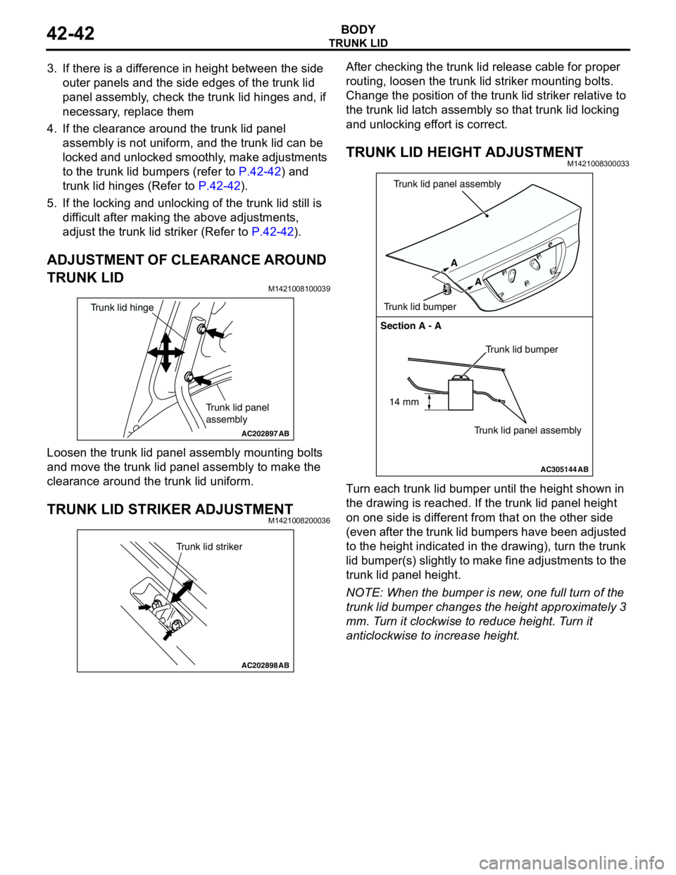
ADJUSTMENT OF CLEARANCE AROUND
TRUNK LID
M1421008100039
Loosen the trunk lid panel assembly mounting bolts
and move the trunk lid panel assembly to make the
clearance around the trunk lid uniform.
TRUNK LID STRIKER ADJUSTMENTM1421008200036
After checking the trunk lid release cable for proper
routing, loosen the trunk lid striker mounting bolts.
Change the position of the trunk lid striker relative to
the trunk lid latch assembly so that trunk lid locking
and unlocking effort is correct.
TRUNK LID HEIGHT ADJUSTMENTM1421008300033
Turn each trunk lid bumper until the height shown in
the drawing is reached. If the trunk lid panel height
on one side is different from that on the other side
(even after the trunk lid bumpers have been adjusted
to the height indicated in the drawing), turn the trunk
lid bumper(s) slightly to make fine adjustments to the
trunk lid panel height.
NOTE: When the bumper is new, one full turn of the
trunk lid bumper changes the height approximately 3
mm. Turn it clockwise to reduce height. Turn it
anticlockwise to increase height.
AC202897
Trunk lid panel
assembly
Trunk lid hinge
AB
AC202898
Trunk lid striker
AB
AC305144
Section A - A
Trunk lid bumper
Trunk lid panel assembly A
A
Trunk lid bumperTrunk lid panel assembly
AB
14 mm
Page 455 of 788
HEADLAMP
CHASSIS ELECTRICAL54A-67
NOTE: Height from the floor to the centre of
the headlamps (Reference value): 840 mm
(3) Measure the distance from the centre line of
the vehicle to the centre of each headlamp.
Transfer the measurement to the screen.
Vertical tape or mark on the screen with
reference to the centre line of each headlamp
bulb.
HEADLAMP ADJUSTMENT
CAUTION
•Do not cover a headlamp for more than three
minutes to prevent the plastic headlamp lens
deformation.
•When adjusting one headlamp beam, make
sure that another headlamp is off by
disconnecting the connector from it. When
reconnecting the connector, make sure that
the headlamp beam is not disturbed
accidentally.
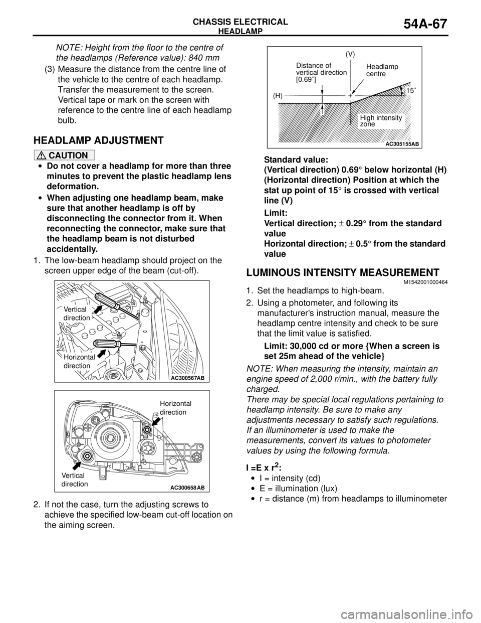
1. The low-beam headlamp should project on the
screen upper edge of the beam (cut-off).
2. If not the case, turn the adjusting screws to
achieve the specified low-beam cut-off location on
the aiming screen.Standard value:
(Vertical direction) 0.69° below horizontal (H)
(Horizontal direction) Position at which the
stat up point of 15° is crossed with vertical
line (V)
Limit:
Vertical direction; ± 0.29° from the standard
value
Horizontal direction; ± 0.5° from the standard
value
LUMINOUS INTENSITY MEASUREMENTM1542001000464
1. Set the headlamps to high-beam.
2. Using a photometer, and following its
manufacturer's instruction manual, measure the
headlamp centre intensity and check to be sure
that the limit value is satisfied.
Limit: 30,000 cd or more {When a screen is
set 25m ahead of the vehicle}
NOTE: When measuring the intensity, maintain an
engine speed of 2,000 r/min., with the battery fully
charged.
There may be special local regulations pertaining to
headlamp intensity. Be sure to make any
adjustments necessary to satisfy such regulations.
If an illuminometer is used to make the
measurements, convert its values to photometer
values by using the following formula.
I =E x r
2:
•I = intensity (cd)
•E = illumination (lux)
•r = distance (m) from headlamps to illuminometer
AC300567AB
Vertical
direction
Horizontal
direction
AC300658AB
Vertical
direction
Horizontal
direction
AC305155
(H)(V)
Distance of
vertical direction
[0.69˚]Headlamp
centre
High intensity
zone
15˚
AB