injector MITSUBISHI LANCER 2005 Workshop Manual
[x] Cancel search | Manufacturer: MITSUBISHI, Model Year: 2005, Model line: LANCER, Model: MITSUBISHI LANCER 2005Pages: 788, PDF Size: 45.98 MB
Page 57 of 788
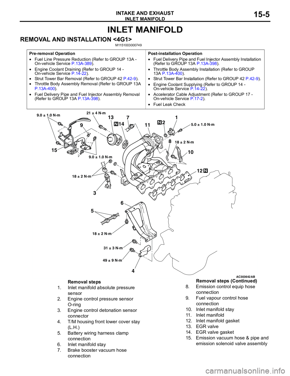
INLET MANIFOLD
INTAKE AND EXHAUST15-5
INLET MANIFOLD
REMOVAL AND INSTALLATION <4G1>M1151003000749
Pre-removal Operation
•Fuel Line Pressure Reduction (Refer to GROUP 13A -
On-vehicle Service P.13A-389).
•Engine Coolant Draining (Refer to GROUP 14 -
On-vehicle Service P.14-22).
•Strut Tower Bar Removal (Refer to GROUP 42 P.42-9).
•Throttle Body Assembly Removal (Refer to GROUP 13A
P.13A-400).
•Fuel Delivery Pipe and Fuel Injector Assembly Removal
(Refer to GROUP 13A P.13A-398).Post-installation Operation
•Fuel Delivery Pipe and Fuel Injector Assembly Installation
(Refer to GROUP 13A P.13A-398).
•Throttle Body Assembly Installation (Refer to GROUP
13A P.13A-400).
•Strut Tower Bar Installation (Refer to GROUP 42 P.42-9).
•Engine Coolant Supplying (Refer to GROUP 14 -
On-vehicle Service P.14-22).
•Accelerator Cable Adjustment (Refer to GROUP 17 -
On-vehicle Service P.17-2).
•Fuel Leak Check
AC303642AB
15
3
6
5
412 10 71
2
11
913
14
21 ± 4 N·m
9.0 ± 1.0 N·m
9.0 ± 1.0 N·m
18 ± 2 N·m
18 ± 2 N·m18 ± 2 N·m5.0 ± 1.0 N·m
31 ± 3 N·m
49 ± 9 N·m
N
N
N
8
Removal steps
1. Inlet manifold absolute pressure
sensor
2. Engine control pressure sensor
O-ring
3. Engine control detonation sensor
connector
4. T/M housing front lower cover stay
(L.H.)
5. Battery wiring harness clamp
connection
6. Inlet manifold stay
7. Brake booster vacuum hose
connection8. Emission control equip hose
connection
9. Fuel vapour control hose
connection
10. Inlet manifold stay
11. Inlet manifold
12. Inlet manifold gasket
13. EGR valve
14. EGR valve gasket
15. Emission vacuum hose & pipe and
emission solenoid valve assembly Removal steps (Continued)
Page 58 of 788
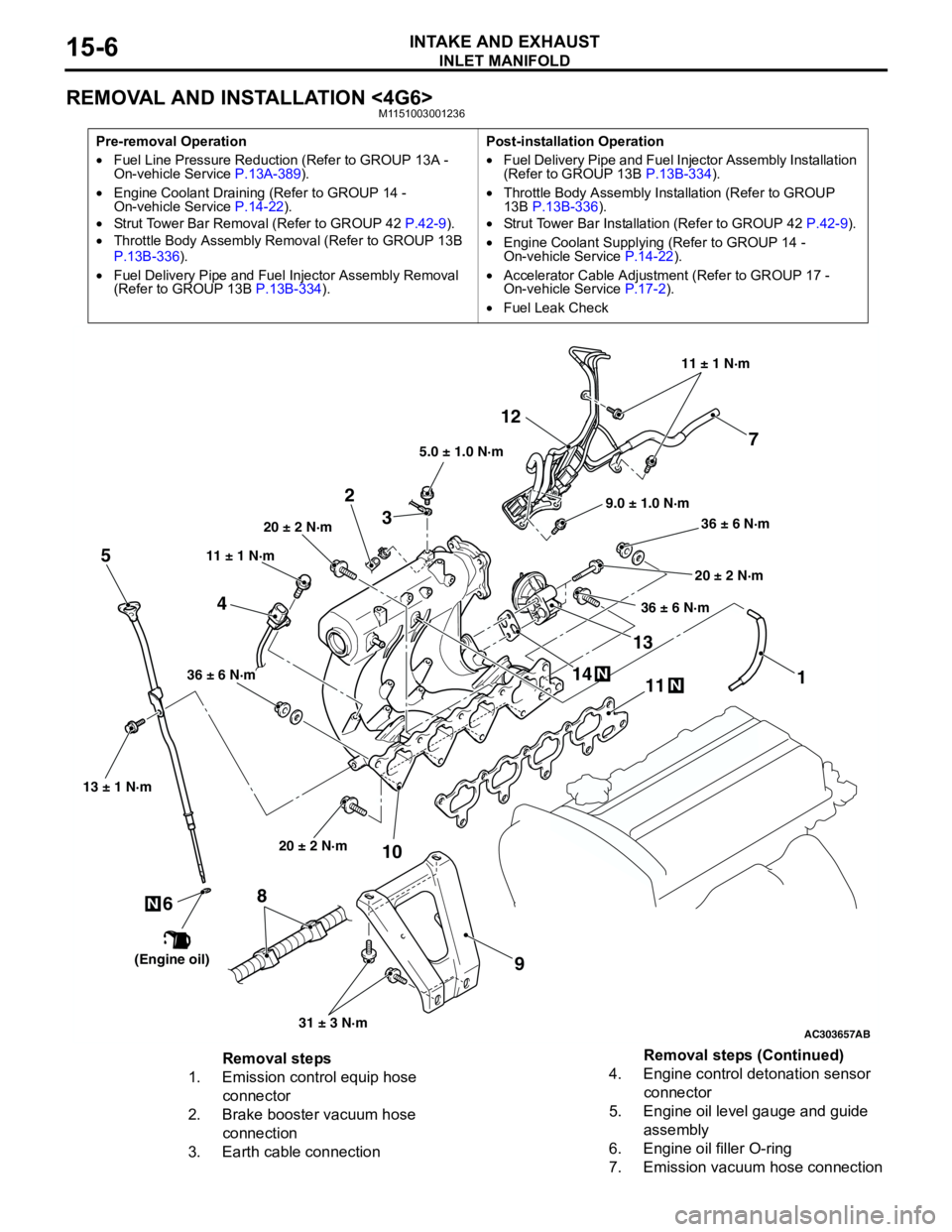
INLET MANIFOLD
INTAKE AND EXHAUST15-6
REMOVAL AND INSTALLATION <4G6>M1151003001236
Pre-removal Operation
•Fuel Line Pressure Reduction (Refer to GROUP 13A -
On-vehicle Service P.13A-389).
•Engine Coolant Draining (Refer to GROUP 14 -
On-vehicle Service P.14-22).
•Strut Tower Bar Removal (Refer to GROUP 42 P.42-9).
•Throttle Body Assembly Removal (Refer to GROUP 13B
P.13B-336).
•Fuel Delivery Pipe and Fuel Injector Assembly Removal
(Refer to GROUP 13B P.13B-334).Post-installation Operation
•Fuel Delivery Pipe and Fuel Injector Assembly Installation
(Refer to GROUP 13B P.13B-334).
•Throttle Body Assembly Installation (Refer to GROUP
13B P.13B-336).
•Strut Tower Bar Installation (Refer to GROUP 42 P.42-9).
•Engine Coolant Supplying (Refer to GROUP 14 -
On-vehicle Service P.14-22).
•Accelerator Cable Adjustment (Refer to GROUP 17 -
On-vehicle Service P.17-2).
•Fuel Leak Check
AC303657
9.0 ± 1.0 N·m11 ± 1 N·m
20 ± 2 N·m
31 ± 3 N·m 36 ± 6 N·m
20 ± 2 N·m
20 ± 2 N·m
36 ± 6 N·m
36 ± 6 N·m
11
9 10 212
N1413N
AB
5.0 ± 1.0 N·m
3
1
11 ± 1 N·m
4
N
13 ± 1 N·m
5
6
(Engine oil)
7
8
Removal steps
1. Emission control equip hose
connector
2. Brake booster vacuum hose
connection
3. Earth cable connection4. Engine control detonation sensor
connector
5. Engine oil level gauge and guide
assembly
6. Engine oil filler O-ring
7. Emission vacuum hose connectionRemoval steps (Continued)
Page 394 of 788
IGNITION SWITCH
CHASSIS ELECTRICAL54A-6
IGNITION SWITCH
GENERAL INFORMATIONM1543009901274
IGNITION KEY REMINDER BUZZER
The ignition key reminder buzzer will sound under
the following condition, and warn the driver to
remove the ignition key.
•The driver's door is opened when the ignition
switch is at "LOCK" (OFF) or "ACC" position
without removing the ignition key.
However, the lamp reminder buzzer will take
precedence over this function.
DOOR LOCK PREVENTION FUNCTION
If the key is left in the ignition switch while the driver’s
door opened or the assistant door opened, all door
are automatically unlock to prevent locking the
ignition key in the vehicle after door is locked.
IMMOBILIZER SYSTEM
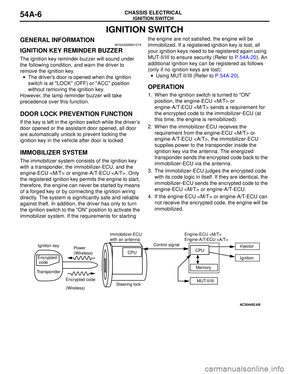
The immobilizer system consists of the ignition key
with a transponder, the immobilizer-ECU, and the
engine-ECU
the registered ignition key permits the engine to start,
therefore, the engine can never be started by means
of a forged key or by connecting the ignition wiring
directly. The system is significantly safe and reliable
against theft. In addition, the driver has only to turn
the ignition switch to the "ON" position to activate the
immobilizer system. If the requirements for starting the engine are not satisfied, the engine will be
immobilized. If a registered ignition key is lost, all
your ignition keys need to be registered again using
MUT-II/III to ensure security (Refer to P.54A-20). An
additional ignition key can be registered as follows
(only if no ignition keys are lost):
•Using MUT-II/III (Refer to P.54A-20).
OPERATION
1. When the ignition switch is turned to "ON"
position, the engine-ECU
engine-A/T-ECU
the encrypted code to the immobilizer-ECU (at
this time, the engine is remobilized).
2. When the immobilizer-ECU receives the
requirement from the engine-ECU
engine-A/T-ECU , the immobilizer-ECU
supplies power to the transponder inside the
ignition key via the antenna. The energized
transponder sends the encrypted code back to the
immobilizer-ECU via the antenna.
3. The immobilizer-ECU judges the encrypted code
with its code logic in itself. If they are identical, the
immobilizer-ECU sends the encrypted code to the
engine-ECU
4. If the engine-ECU
not receive the encrypted code, the engine will be
immobilized.
AC304482AB
Power
(Wireless)
Encrypted code
(Wireless) Ignition keyControl signal
Encrypted
code
TransponderImmobilizer-ECU
with an antenna
Steering lockCPU
MUT-II/III Memory Engine-ECU
Engine-A/T-ECU
CPUInjector
Ignition
Page 406 of 788
IGNITION SWITCH
CHASSIS ELECTRICAL54A-18
INSPECTION PROCEDURE 2: The Ignition Key cannot be Registered.
TECHNICAL DESCRIPTION (COMMENT)
The ignition key transponder or the immobilizer-ECU
is suspected to be defective.
TROUBLESHOOTING HINTS
•Malfunction of the ignition key
•Malfunction of immobilizer-ECU
DIAGNOSIS PROCEDURE
STEP 1. MUT-II/III diagnosis code.
Q: Does diagnosis code No.11 reset?
YES :
Refer to P.54A-9.
NO : Replace the ignition key that cannot be
registered. Then re-register the encrypted
code. (Refer to P.54A-20). Verify that the
ignition key can be registered, then Go to
Step 2.
STEP 2. Retest the system.
Q: Does registered ignition key function properly?
YES :
The procedure is complete. (If no
malfunctions are found in all steps, an
intermittent malfunction is suspected. Refer
to GROUP 00, How to Use
Troubleshooting/Inspection Service Points −
How to Cope with Intermittent Malfunction
P.00-5).
NO : Replace the immobilizer-ECU.
INSPECTION PROCEDURE 3: Engine does not Start (Cranking but no Initial Combustion).
TECHNICAL DESCRIPTION (COMMENT)
If the fuel injectors are not operating, there might be
a problem with the MPI system in addition to a
malfunction of the immobilizer system. It is normal for
this to occur if an attempt is made to start the engine
using a key that has not been properly registered.
TROUBLESHOOTING HINTS
•Malfunction of MPI system
•Malfunction of immobilizer-ECU
DIAGNOSIS PROCEDURE
STEP 1. Check the system voltage.
Measure the system voltage during cranking.
Q: Is the voltage 8 volts or more?
YES :
Go to Step 2.
NO : Check the battery. Refer to P.54A-4. The
engine should start.
STEP 2. Check the immobilizer system diagnosis
code and MPI system diagnosis code.
Q: Which diagnosis code resets, the immobilizer
system diagnosis code or the MPI system
diagnosis code?
Immobilizer system diagnosis code is set :
Refer
to P.54A-9.
MPI system diagnosis code is set : Refer to
GROUP 13A, Diagnosis P.13A-15, GROUP
13B, Diagnosis P.13B-15.
No diagnosis code is set : Go to Step 3.
STEP 3. Check the starting system.
Q: Does the engine start?
YES :
Go to Step 4.
NO : Refer to GROUP 13A, Diagnosis −
Symptom Chart P.13A-215, GROUP 13B,
Diagnosis − Symptom Chart P.13B-189. If
the malfunction is not resolved, replace the
immobilizer-ECU. Then register the
password (secret code) and encrypted
code. (Refer to P.54A-20.) The engine
should start.
Page 614 of 788
ENGINE AND TRANSMISSION
CONFIGURATION DIAGRAMS80-8
ENGINE AND TRANSMISSION
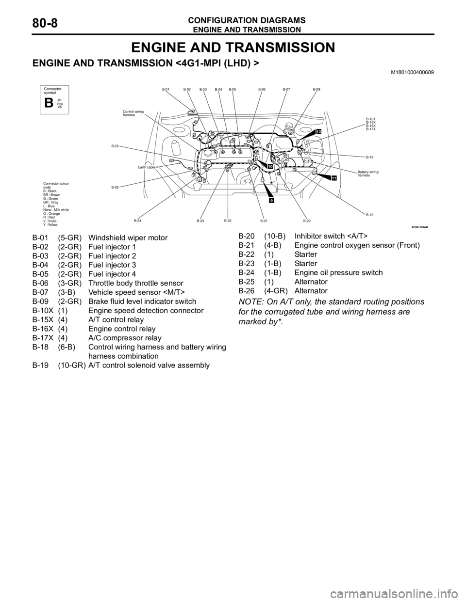
ENGINE AND TRANSMISSION <4G1-MPI (LHD) >M1801000400689
NOTE: On A/T only, the standard routing positions
for the corrugated tube and wiring harness are
marked by*.
AC301128
B-02
B-03B-04B-05
B-22
B-23 B-24 B-25 B-26Control wiring
harnessB-01
Connector colour
code
B : Black
BR : Brown
G : Green
GR : Gray
L : Blue
None : Milk white
O : Orange
R : Red
V : Violet
Y : Yellow*
Connector
symbol
-01
thru
-26B
Earth cable
AB
9
10
11
13
B-06B-07
B-09
B-10X
B-15X
B-16X
B-17X
B-18
Battery wiring
harness
B-19
B-20
B-21
*
B-01 (5-GR) Windshield wiper motor
B-02 (2-GR) Fuel injector 1
B-03 (2-GR) Fuel injector 2
B-04 (2-GR) Fuel injector 3
B-05 (2-GR) Fuel injector 4
B-06 (3-GR) Throttle body throttle sensor
B-07 (3-B) Vehicle speed sensor
B-09 (2-GR) Brake fluid level indicator switch
B-10X (1) Engine speed detection connector
B-15X (4) A/T control relay
B-16X (4) Engine control relay
B-17X (4) A/C compressor relay
B-18 (6-B) Control wiring harness and battery wiring
harness combination
B-19 (10-GR) A/T control solenoid valve assemblyB-20 (10-B) Inhibitor switch
B-21 (4-B) Engine control oxygen sensor (Front)
B-22 (1) Starter
B-23 (1-B) Starter
B-24 (1-B) Engine oil pressure switch
B-25 (1) Alternator
B-26 (4-GR) Alternator
Page 616 of 788
ENGINE AND TRANSMISSION
CONFIGURATION DIAGRAMS80-10
ENGINE AND TRANSMISSION
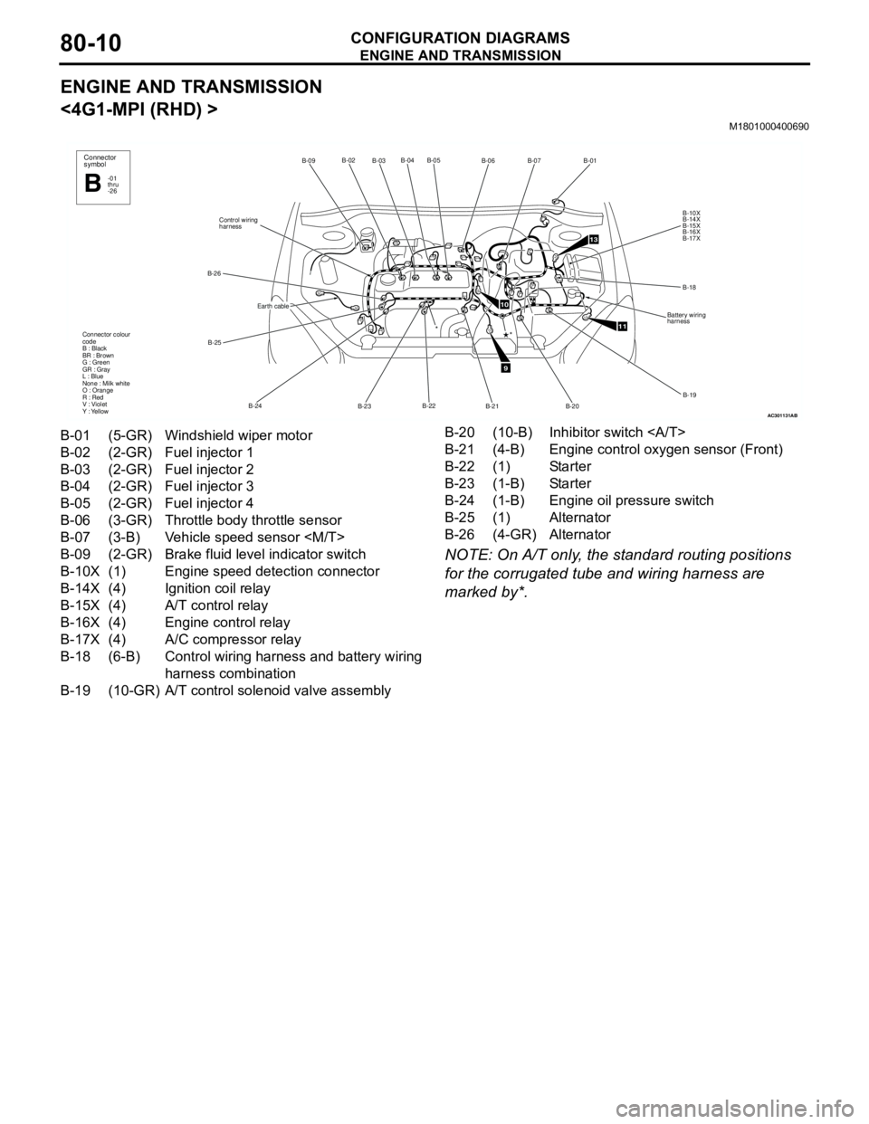
<4G1-MPI (RHD) >
M1801000400690
NOTE: On A/T only, the standard routing positions
for the corrugated tube and wiring harness are
marked by*.
AC301131
B-02
B-03B-04 B-05
B-22
B-23 B-24 B-25 B-26Control wiring
harnessB-09
Connector colour
code
B : Black
BR : Brown
G : Green
GR : Gray
L : Blue
None : Milk white
O : Orange
R : Red
V : Violet
Y : Yellow*
Connector
symbol
-01
thru
-26B
Earth cable
AB
9
10
11
13
B-06B-07
B-01
B-10X
B-14X
B-15X
B-16X
B-17X
B-18
Battery wiring
harness
B-19
B-20 B-21
*
B-01 (5-GR) Windshield wiper motor
B-02 (2-GR) Fuel injector 1
B-03 (2-GR) Fuel injector 2
B-04 (2-GR) Fuel injector 3
B-05 (2-GR) Fuel injector 4
B-06 (3-GR) Throttle body throttle sensor
B-07 (3-B) Vehicle speed sensor
B-09 (2-GR) Brake fluid level indicator switch
B-10X (1) Engine speed detection connector
B-14X (4) Ignition coil relay
B-15X (4) A/T control relay
B-16X (4) Engine control relay
B-17X (4) A/C compressor relay
B-18 (6-B) Control wiring harness and battery wiring
harness combination
B-19 (10-GR) A/T control solenoid valve assemblyB-20 (10-B) Inhibitor switch
B-21 (4-B) Engine control oxygen sensor (Front)
B-22 (1) Starter
B-23 (1-B) Starter
B-24 (1-B) Engine oil pressure switch
B-25 (1) Alternator
B-26 (4-GR) Alternator
Page 618 of 788
ENGINE AND TRANSMISSION
CONFIGURATION DIAGRAMS80-12
ENGINE AND TRANSMISSION
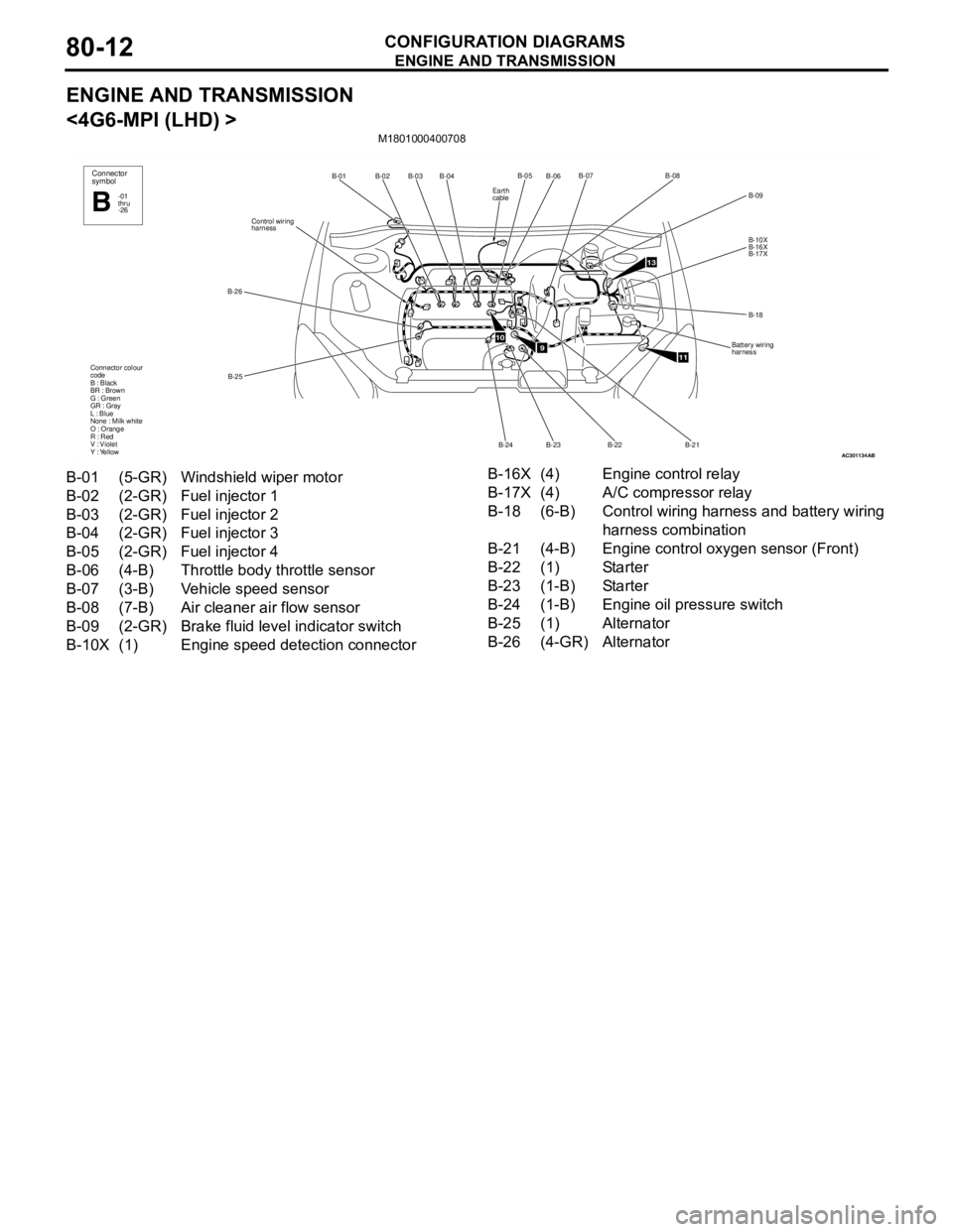
<4G6-MPI (LHD) >
M1801000400708
AC301134
B-02
B-03B-04
B-25 B-26Control wiring
harnessB-01
Connector colour
code
B : Black
BR : Brown
G : Green
GR : Gray
L : Blue
None : Milk white
O : Orange
R : Red
V : Violet
Y : YellowConnector
symbol
-01
thru
-26B
AB
910
11
13
B-06B-07
B-09
B-10X
B-16X
B-17X
B-18
Battery wiring
harness
B-21 B-22
B-23B-05B-08
B-24
Earth
cable
B-01 (5-GR) Windshield wiper motor
B-02 (2-GR) Fuel injector 1
B-03 (2-GR) Fuel injector 2
B-04 (2-GR) Fuel injector 3
B-05 (2-GR) Fuel injector 4
B-06 (4-B) Throttle body throttle sensor
B-07 (3-B) Vehicle speed sensor
B-08 (7-B) Air cleaner air flow sensor
B-09 (2-GR) Brake fluid level indicator switch
B-10X (1) Engine speed detection connectorB-16X (4) Engine control relay
B-17X (4) A/C compressor relay
B-18 (6-B) Control wiring harness and battery wiring
harness combination
B-21 (4-B) Engine control oxygen sensor (Front)
B-22 (1) Starter
B-23 (1-B) Starter
B-24 (1-B) Engine oil pressure switch
B-25 (1) Alternator
B-26 (4-GR) Alternator
Page 620 of 788
ENGINE AND TRANSMISSION
CONFIGURATION DIAGRAMS80-14
ENGINE AND TRANSMISSION
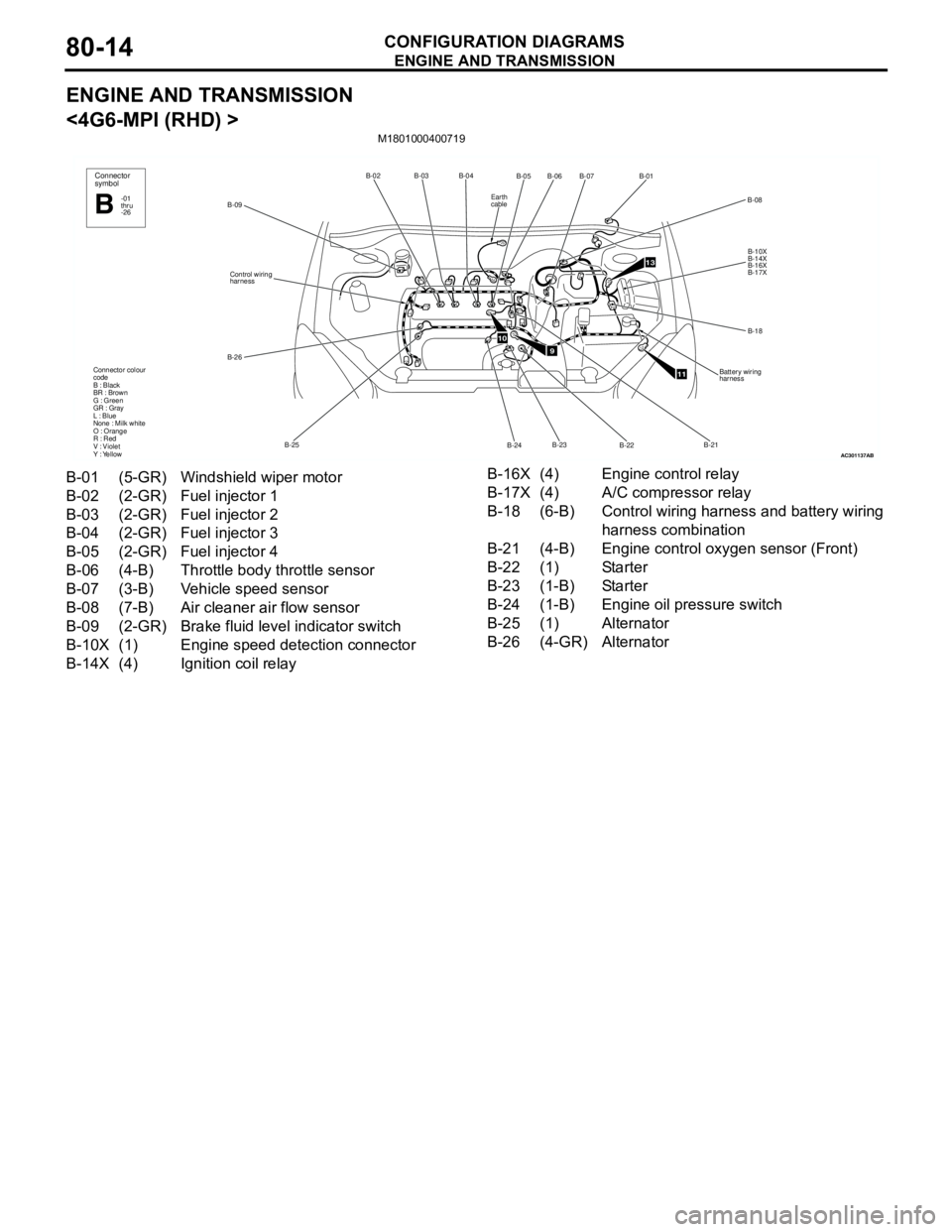
<4G6-MPI (RHD) >
M1801000400719
AC301137
B-02B-03B-04
B-25 B-26Control wiring
harness
B-09
Connector colour
code
B : Black
BR : Brown
G : Green
GR : Gray
L : Blue
None : Milk white
O : Orange
R : Red
V : Violet
Y : Yellow
Connector
symbol
-01
thru
-26B
AB
910
11
13
B-05
B-07B-01
B-10X
B-14X
B-16X
B-17X
B-18
Battery wiring
harness
B-22 B-24B-06
B-08
B-23B-21
Earth
cable
B-01 (5-GR) Windshield wiper motor
B-02 (2-GR) Fuel injector 1
B-03 (2-GR) Fuel injector 2
B-04 (2-GR) Fuel injector 3
B-05 (2-GR) Fuel injector 4
B-06 (4-B) Throttle body throttle sensor
B-07 (3-B) Vehicle speed sensor
B-08 (7-B) Air cleaner air flow sensor
B-09 (2-GR) Brake fluid level indicator switch
B-10X (1) Engine speed detection connector
B-14X (4) Ignition coil relayB-16X (4) Engine control relay
B-17X (4) A/C compressor relay
B-18 (6-B) Control wiring harness and battery wiring
harness combination
B-21 (4-B) Engine control oxygen sensor (Front)
B-22 (1) Starter
B-23 (1-B) Starter
B-24 (1-B) Engine oil pressure switch
B-25 (1) Alternator
B-26 (4-GR) Alternator
Page 648 of 788
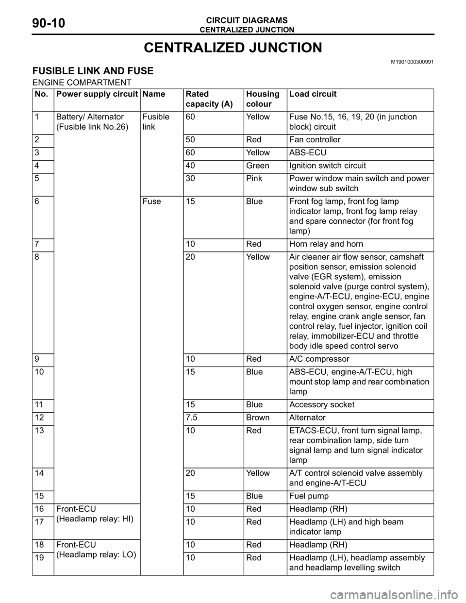
CENTRALIZED JUNCTION
CIRCUIT DIAGRAMS90-10
CENTRALIZED JUNCTION
M1901000300991
FUSIBLE LINK AND FUSE
ENGINE COMPARTMENT
No. Power supply circuit Name Rated
capacity (A)Housing
colourLoad circuit
1 Battery/ Alternator
(Fusible link No.26)Fusible
link60 Yellow Fuse No.15, 16, 19, 20 (in junction
block) circuit
2 50 Red Fan controller
3 60 Yellow ABS-ECU
4 40 Green Ignition switch circuit
5 30 Pink Power window main switch and power
window sub switch
6 Fuse 15 Blue Front fog lamp, front fog lamp
indicator lamp, front fog lamp relay
and spare connector (for front fog
lamp)
7 10 Red Horn relay and horn
8 20 Yellow Air cleaner air flow sensor, camshaft
position sensor, emission solenoid
valve (EGR system), emission
solenoid valve (purge control system),
engine-A/T-ECU, engine-ECU, engine
control oxygen sensor, engine control
relay, engine crank angle sensor, fan
control relay, fuel injector, ignition coil
relay, immobilizer-ECU and throttle
body idle speed control servo
9 10 Red A/C compressor
10 15 Blue ABS-ECU, engine-A/T-ECU, high
mount stop lamp and rear combination
lamp
11 15 Blue Accessory socket
12 7.5 Brown Alternator
13 10 Red ETACS-ECU, front turn signal lamp,
rear combination lamp, side turn
signal lamp and turn signal indicator
lamp
14 20 Yellow A/T control solenoid valve assembly
and engine-A/T-ECU
15 15 Blue Fuel pump
16 Front-ECU
(Headlamp relay: HI)10 Red Headlamp (RH)
17 10 Red Headlamp (LH) and high beam
indicator lamp
18 Front-ECU
(Headlamp relay: LO)10 Red Headlamp (RH)
19 10 Red Headlamp (LH), headlamp assembly
and headlamp levelling switch
Page 668 of 788

ENGINE CONTROL SYSTEM <4G1-M/T (LHD)>
CIRCUIT DIAGRAMS90-30
ENGINE CONTROL SYSTEM <4G1-M/T (LHD)> (CONTINUED)
ENGINE CONTROL SYSTEM <4G1-M/T (LHD)> (CONTINUED)
ENGINE CONTROL
RELAY
FUEL
INJECTOR 1FUEL
INJECTOR 2FUEL
INJECTOR 3FUEL
INJECTOR 4
ENGINE-
ECU
ENGINE CONTROL
OXYGEN SENSOR
(REAR)ENGINE
CONTROL
OXYGEN
SENSOR
(FRONT)
INLET MANIFOLD
ABSOLUTE PRESSURE SENSORWATER
TEMPERA-
TURE
SENSOR
UNITTHROTTLE
BODY
THROTTLE
SENSOR EMISSION
SOLENOID
VALVE
(PURGE
CONTROL
SYSTEM)EMISSION
SOLENOID
VALVE
(EGR
SYSTEM)CAMSHAFT
POSITION
SENSORENGINE
CRANK
ANGLE
SENSOR
OUTPUT GNDPOWER
SOURCE
INTAKE AIR
TEMPERATURE
SENSOR
Wire colour code
B : Black LG : Light green G : Green L : Blue W : White Y : Yellow SB : Sky blue
BR : Brown O : Orange GR : Gray R : Red P : Pink V : Violet
CHARGING
SYSTEMMANUAL AIR
CONDITIONER
·MANUAL AIR
CONDITIONER ·COOLING
SYSTEMTHROTTLE
BODY
IDLE SPEED
CONTROL
SERVO
ENGINE-ECU
ENGINE CONTROL
DETONATION
SENSOR
IMMOBILIZER
SYSTEMIGNITION
SYSTEM
FRONT
SIDE
ENGINE-
ECU
(FUSE )2
(FUSE )15
DIAGNOSIS
CONNECTOR
DIAGNOSIS
CONNECTOR
POWER
STEERING
FLUID PRESSURE
SWITCHENGINE
SPEED
DETECTION
CONNECTOR VEHICLE
SPEED
SENSOR
METER AND
GAUGE
Wire colour code
B : Black LG : Light green G : Green L : Blue W : White Y : Yellow SB : Sky blue
BR : Brown O : Orange GR : Grey R : Red P : Pink V : Violet
FRONT
SIDE