fluid MITSUBISHI LANCER 2006 Workshop Manual
[x] Cancel search | Manufacturer: MITSUBISHI, Model Year: 2006, Model line: LANCER, Model: MITSUBISHI LANCER 2006Pages: 800, PDF Size: 45.03 MB
Page 137 of 800
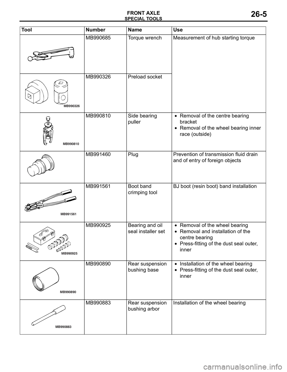
SPECIA L T OOLS
FRONT AXLE26-5
MB990685To rqu e wrenchMeas urement o f hub st arting torque
MB990326
MB990326 Prel oad socket
MB990810
MB990810Side be aring
puller•Removal of the centre b earing
bra
c ke t
•Removal of the whee l bea ring inner
r
a ce (o ut side )
MB991460PlugPreven tion of transmission fluid drain
and o
f entry of fore ign o b ject s
MB991561
MB991561Boot ban d
crimpin
g toolBJ boot (resin bo ot) ban d inst a lla tion
MB990925
MB990925Bearing and o il
seal
inst a lle r set•Removal of the whee l bea ring
•Removal and inst a lla tion o f the
centre
bearing
•Press-f i ttin g of th e dust se al ou ter ,
inner
MB990890
MB990890Rear suspension
bush
i ng b a se•In st allatio n of th e wheel bearing
•Press-f i ttin g of th e dust se al ou ter ,
inner
MB990883
MB990883Rear suspension
bush
i ng a r borInstallation of t he wheel bearing
Tool Nu mber Na me Use
Page 146 of 800
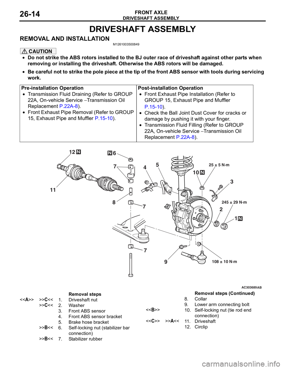
DRIVESHAFT ASSEMBLY
FRONT AXLE26-14
DRIVESHAFT ASSEMBLY
REMOVAL AND INSTALLATIONM1261003500849
CAUTION
•Do not strike the ABS rotors installed to the BJ outer race of driveshaft against other parts when
removing or installing the driveshaft. Otherwise the ABS rotors will be damaged.
•
Pre-installation Operation
•Transmission Fluid Draining (Refer to GROUP
22A, On-vehicle Service
− Transmission Oil
Replacement
P.22A-8).
•Front Exhaust Pipe Removal (Refer to GROUP
15, Exhaust Pipe and Muffler
P.15-10).
Post-installation Operation
•Front Exhaust Pipe Installation (Refer to
GROUP 15, Exhaust Pipe and Muffler
P.15-10).
•Check the Ball Joint Dust Cover for cracks or
damage by pushing it with your finger.
•Transmission Fluid Filling (Refer to GROUP
22A, On-vehicle Service
− Transmission Oil
Replacement
P.22A-8).
AC303689AB
9
N
N
NN
10
7
4
3
2 1
25 ± 5 N·m
245 ± 29 N·m
108 ± 10 N·m
8
5
6
11 12
77
Removal steps
<>>>C<<1.Driveshaft nut
>>C<<2.Washer
3.Front ABS sensor
4.Front ABS sensor bracket
5.Brake hose bracket
>>B<<6.Self-locking nut (stabilizer bar
connection)
>>B<<7.Stabilizer rubber
8.Collar
9.Lower arm connecting bolt
<>10.Self-locking nut (tie rod end
connection)
<
12.Circlip
Be careful not to strike the pole piece at the tip of the front ABS sensor with tools during servicing
work.
Removal steps (Continued)
Page 178 of 800
CROSSMEMBER
POWER PLANT MOUNT32-8
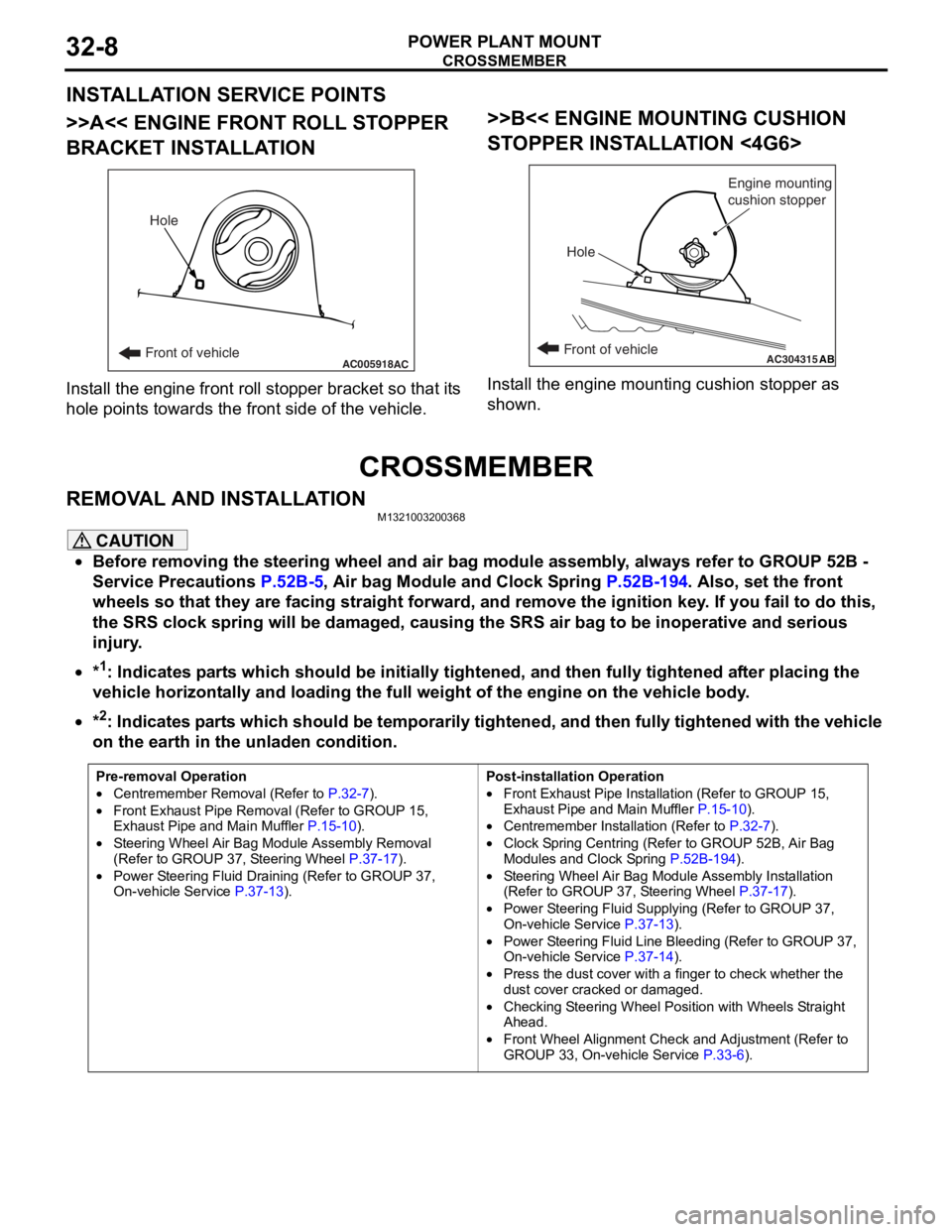
INSTALLATION SERVICE POINTS
>>A<< ENGINE FRONT ROLL STOPPER
BRACKET INSTALLATION
AC005918Front of vehicleHoleAC
Inst
all th e en gine fron t roll stop per b r acket so that it s
hole
point s towards the fro n t side of the vehicle.
>>B<< ENGINE MOUNTING CUSHION
ST
OPPER INST ALLA TION <4G6>
AC304315ABFront of vehicle
Hole Engine mounting
cushion stopper
Inst
all the e ngin e mo untin g cushio n sto pper a s
shown.
CROSSMEMBER
REMOVA L AND INST ALLA TIONM13210032 0036 8
CAUTION
•Before removing the steering wheel and air bag module assembly, always refer to GROUP 52B -
Service Precautions
P.52B-5, Air bag Module and Clock Spring P.52B-194. Also, set the front
wheels so that they are facing straight forward, and remove the ignition key. If you fail to do this,
the SRS clock spring will be damaged, causing the SRS air bag to be inoperative and serious
injury.
•*1: Indicates parts which should be initially tightened, and then fully tightened after placing the
vehicle horizontally and loading the full weight of the engine on the vehicle body.
•
Pre-removal Operation
•Centremember Removal (Refer to P.32-7).
•Front Exhaust Pipe Remova l (Refer to GROUP 15,
Exhaust Pipe and Main Muffler P.15-10).
•Steering Wheel Air Bag Mo dule Assembly Removal
(Refer to GROUP 37, Steering Wheel P.37-17).
•Power Steering Fluid Draining (Refer to GROUP 37,
On-vehicle Service P.37-13).
Post-installation Operation
•Front Exhaust Pipe Installation (Refer to GROUP 15,
Exhaust Pipe and Main Muffler
P.15-10).
•Centremember Installation (Refer to P.32-7).
•Clock Spring Centring (Refer to GROUP 52B, Air Bag
Modules and Clock Spring P.52B-194).
•Steering Wheel Air Bag Module Assembly Installation
(Refer to GROUP 37, Steering Wheel P.37-17).
•Power Steering Fluid Supplying (Refer to GROUP 37,
On-vehicle Service P.37-13).
•Power Steering Fluid Line Bleeding (Refer to GROUP 37,
On-vehicle Service P.37-14).
•Press the dust cover with a finger to check whether the
dust cover cracked or damaged.
•Checking Steering Wheel Position with Wheels Straight
Ahead.
•Front Wheel Alignment Check and Adjustment (Refer to
GROUP 33, On-vehicle Service P.33-6).
*2: Indicates parts which should be temporarily tightened, and then fully tightened with the vehicle
on the earth in the unladen condition.
Page 210 of 800
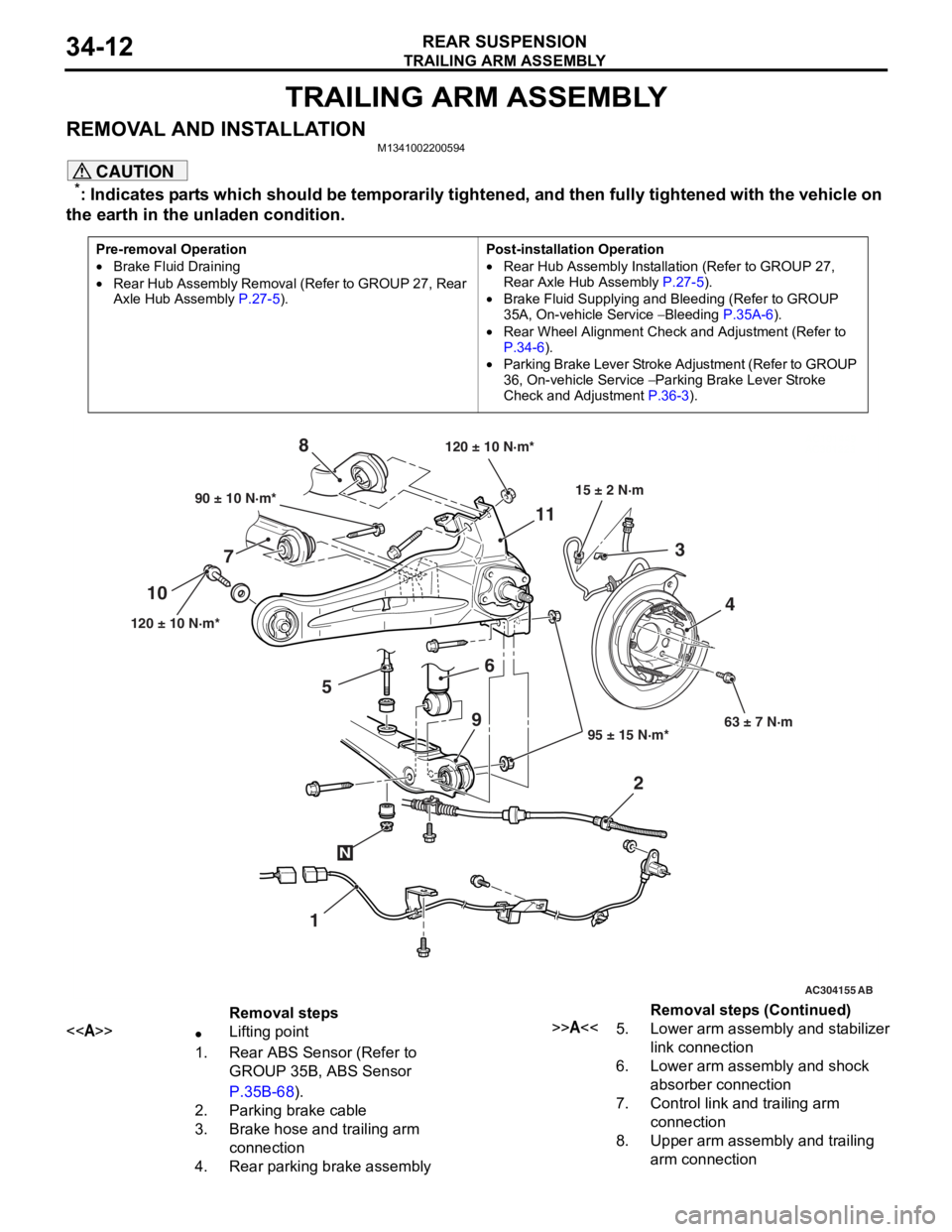
TRAILING ARM ASSEMBLY
REAR SUSPENSION34-12
TRAILING ARM ASSEMBLY
REMOVAL AND INSTALLATIONM1341002200594
CAUTION
*: Indicates parts which should be temporarily tightened, and then fully tightened with the vehicle on
the earth in the unladen condition.
Pre-removal Operation
•Brake Fluid Draining
•Rear Hub Assembly Removal (Refer to GROUP 27, Rear
Axle Hub Assembly P.27-5).
Post-installation Operation
•Rear Hub Assembly Installation (Refer to GROUP 27,
Rear Axle Hub Assembly
P.27-5).
•Brake Fluid Supplying and Bleeding (Refer to GROUP
35A, On-vehicle Service
− Bleeding P.35A-6).
•Rear Wheel Alignment Check and Adjustment (Refer to
P.34-6).
•Parking Brake Lever Stroke Ad justment (Refer to GROUP
36, On-vehicle Service
− Parking Brake Lever Stroke
Check and Adjustment
P.36-3).
AC101449
AC301223
AC304155 AB
90 ± 10 N·m*
120 ± 10 N·m* 95 ± 15 N·m*63 ± 7 N·m
6
7 8
1
10
11
23
4
120 ± 10 N·m*
15 ± 2 N·m
N
9
5
Removal steps
<>•Lifting point
1.Rear ABS Sensor (Refer to
GROUP 35B, ABS Sensor
P.35B-68).
2.Parking brake cable
3.Brake hose and trailing arm
connection
4.Rear parking brake assembly
>>A<<5.Lower arm assembly and stabilizer
link connection
6.Lower arm assembly and shock
absorber connection
7.Control link and trailing arm
connection
8.Upper arm assembly and trailing
arm connection
Removal steps (Continued)
Page 231 of 800
37-1
GROUP 37
POWER STEERING
CONTENTS
GENERAL INFORMATION . . . . . . . .37-3
SERVICE SPECIFICATIONS . . . . . . .37-6
LUBRICANTS . . . . . . . . . . . . . . . . . .37-7
SEALANTS . . . . . . . . . . . . . . . . . . . .37-7
SPECIAL TOOLS . . . . . . . . . . . . . . . .37-8
ON-VEHICLE SERVICE . . . . . . . . . . .37-11
STEERING WHEEL FREE PLAY CHECK . 37-11
STEERING ANGLE CHECK . . . . . . . . . . . . 37-11
TIE ROD END BALL JOINT TURNING
TORQUE CHECK . . . . . . . . . . . . . . . . . . . . 37-12
STATIONARY STEERING EFFORT
CHECK . . . . . . . . . . . . . . . . . . . . . . . . . . . . 37-12
STEERING WHEEL RETURN TO
CENTRE CHECK . . . . . . . . . . . . . . . . . . . . 37-13
DRIVE BELT TENSION CHECK. . . . . . . . . 37-13
FLUID LEVEL CHECK . . . . . . . . . . . . . . . . 37-13
FLUID REPLACEMENT . . . . . . . . . . . . . . . 37-13
POWER STEERING SYSTEM AIR
BLEEDING . . . . . . . . . . . . . . . . . . . . . . . . . 37-14
OIL PUMP PRESSURE TEST . . . . . . . . . . 37-14
POWER STEERING PRESSURE
SWITCH CHECK . . . . . . . . . . . . . . . . . . . . . 37-15
TIE ROD END BALL JOINT DUST
COVER CHECK . . . . . . . . . . . . . . . . . . . . . 37-15
STEERING COLUMN SHAFT ASSEMBLY
SHOCK ABSORBING MECHANISM
CHECK . . . . . . . . . . . . . . . . . . . . . . . . . . . . 37-15
STEERING WHEEL . . . . . . . . . . . . . .37-17
REMOVAL AND INSTALLATION
REMOVAL AND INSTALLATION
Continued on next page
WARNINGS REGARDING SERVICING OF SUPPLEMENTAL RESTRAINT SYSTEM (SRS) EQUIPPED VEHICLES
WARNING
•Improper service or maintenance of any component of the SRS, or any SRS-related component, can lead to
personal injury or death to service personnel (from inad vertent firing of the air bag) or to the driver and
paassenger (from renderin g the SRS inoperative).
•Service or maintenance of any SRS component or SRS-related component must be performed only at an
authorized MITSUBISHI dealer.
•MITSUBISHI dealer personnel must thoroughly review th is manual, and especially its GROUP 52B - Supplemental
Restraint System (SRS) before begi nning any service or maintenance of any component of the SRS or any
SRS-related component.
NOTE
The SRS includes the following components: SRS air bag control unit, SRS warning light, front impact sensors, air bag module,
clock spring, and interconnecting wiring. Other SRS-related components (that may have to be removed/installed in connection
with SRS service or maintenance) are indicated in the table of contents by an asterisk (*).
Page 233 of 800

GENERAL INFORMATION
POWER STEERING37-3
GENERAL INFORMATION
M1372000100661
Power steering has been adopted in all vehicles to
make the steering system easier to handle.
FEATURES
•A 4-spoke steering wheel is used.
•MOMO leather-wrapped 3-spoke steering wheel
is used.
•A steering column has a shock absorbing mecha-
nism and a tilt steering mechanism.
•Integral-type rack and pinion gear with high rigid-
ity and excellent response is used.
•A vane type pump with a fluid flow rate control
system which change steering effort according to
the engine speed is used.
•The separate plastic resin oil reservoir is used to
reduce weight and to make the fluid level check
-
ing easier.
SPECIFICATIONS
ItemInviteIntense
Steering
wheelTy p e4-spoke typeMOMO leather-wrapped
3-spoke type
Outside diameter mm380365
Maximum number of turns3.193.08
Steering
columnColumn mechanismShock absorbing mechanism and Tilt steering mechanism
Power steering typeIntegral type
Oil pumpTy p eVane pump
Basic discharge amount cm3/rev.7.2 <1300, 1600>
8.1 <2000>
7.2 <1300, 1600>
8.1 <2000>
Relief pressure MPa8.88.8
Reservoir typeSeparate type (plastic)
Pressure switchEquipped
Steering
gearTy p eRack and pinion
Stroke ratio (Rack stroke/Steering
wheel maximum turning radius)45.7445.74
Rack stroke mm146141
Page 237 of 800

LUBRICANTS
POWER STEERING37-7
LUBRICANTS
M1372000400350
ItemSpecified lubricantQuantity
Power steering fluidATF DEXRON III or DEXRON IIApproximately 1.0 L
Steering gearBearingATF DEXRON III or DEXRON IIAs required
O-ring and seal ring
Oil seal
Special tool (MB991212,
MB991213)
Pinion and valve assembly
seal ring part
BellowsSilicon greaseAs required
Tie rod end ball jointMultipurpose grease SAE J310,
NLGI No.2 or equivalentAs required
Oil pumpFriction surface of rotor vane,
cam ring and pump coverATF DEXRON III or DEXRON IIAs required
O-ring
SEALANTS
M1372000500357
ItemSpecified sealant
Steering shaft cover assembly bolt hole on the toeboard3M ATD Part No.8513 or equivalent
Steering gearEnd plug3M ATD Part No.8661 or equivalent
Rack support cover
Page 243 of 800
ON-VEHICLE SERVICE
POWER STEERING37-13
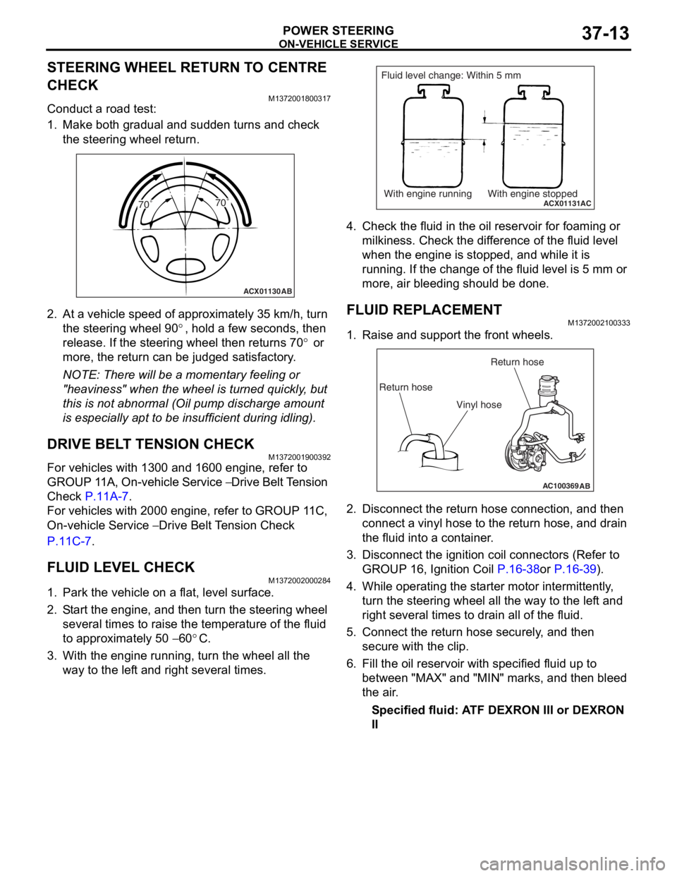
STEERING WHEEL RETURN TO CENTRE
CHECK
M1372001800317
Conduct a road test:
1. Make both gradual and sudden turns and check the steering wheel return.
ACX01130 AB
70˚ 70˚
2.
At a vehicle sp eed of a pproxima t ely 35 km/h, turn
th e ste e ring wh eel 9 0
°, ho ld a few se cond s, the n
release. If th
e ste
e
ring
wh eel t hen ret u rns 7 0
° or
more, th
e return
can
be ju
dged satisfactory
.
NOTE: There will be a mome nt a r y fee lin g or
"he
a
viness" when t he wheel is turned quickly , but
th
is is n o t abno rmal (Oil pu mp discharge amou nt
is especially a p t to b e insufficie n t during id lin g).
DRIVE BELT TENSION CHECK
M13720019 0039 2
For vehicles with 13 00 and 1600 engin e , refer to
GROUP 1
1 A, On-vehicle Service
− Drive Belt T ension
Che
c
k
P.11A-7.
For veh i cles wit h 2000 e ngin e , refer to GROUP 1 1 C,
On-vehicle Se
rvice
− Drive Belt Te nsion Check
P.1 1 C - 7.
FLUID LEVEL CHECK
M13720020 0028 4
1.Park the vehicle on a f l at, leve l su rface .
2.S t art the engine, and t hen tu rn the ste e ring wheel
seve ral times to raise the temperat ure of th e flu i d
to approximately 50
− 60°C.
3.With the engine run n ing, turn the wheel all the
way to the lef t an d righ t several times.
ACX01131With engine running With engine stoppedAC
Fluid level change: Within 5 mm
4.Check t he flu i d in the oil r e servoir f o r foaming or
milkine s s. Check the d i f f e r ence of the fluid le vel
when the e ngine is stop ped, an d while it is
ru nning . If the chan ge of th e fluid le vel is 5 mm or
more, a i r bleedin g sh ould be don e.
FLUID REPLACEMENT
M13720021 0033 3
1.Raise a nd su pport t he fron t wheels.
AC100369AB
Return hoseReturn hose
Vinyl hose
2. Disco nnect the re turn hose connection , and then
conne ct a vinyl hose to the re turn h o se, and drain
th e flu i d into a cont ain e r .
3.Disco nnect the ignition coil con necto rs (Refe r to
GROUP 16, Ignition Coil
P.16-38or P.16-39).
4.Wh ile operat ing th e st arter moto r inter m itt ently ,
tu rn the steering whee l all the wa y to t he le f t a nd
right seve ral times to dra i n all of the fluid.
5.Conn ect the retu rn hose se curely , and then
secu re with t he clip.
6.Fill the oil reservo i r with specified fluid u p to
b e tween "MAX" and "MIN" marks, and then bleed
th e air .
Specified fluid: A TF DEXRON III or DEXRON
II
Page 244 of 800
ON-VEHICLE SERVICE
POWER STEERING37-14
POWER STEERING SYSTEM AIR
BLEEDING
M1372002200330
Perform air bleeding procedure as necessary after
replacing the steering gear or the steering fluid lines.
1. Raise and support the front wheels.
2. Disconnect the ignition coil connectors (Refer to GROUP 16, Ignition Coil
P.16-38 or P.16-39).
CAUTION
Perform air bleeding only while cranking the
engine. If air bleeding is performed while the
engine is running, air could enter the fluid. Dur
-
ing air bleeding, refill the steering fluid supply so
that the level never falls below the "MIN" mark on
the oil reservoir.
3. Turn the steering wheel all the way to the left and
right five or six times wh ile using the starter motor
to crank the engine intermittently several times
(for 15 to 20 seconds).
4. Connect the ignition coil connectors (Refer to GROUP 16, Ignition Coil
P.16-38 or P.16-39).
5. Start the engine (idling).
6. Turn the steering wheel to the left and right until there are no air bubbles in the oil reservoir.
7. Confirm that the fluid is not milky, and that the level is between "MAX" and "MIN" marks.
8. Confirm that there is very little change in the fluid
level when the steering wheel is turned left and
right.
CAUTION
If the fluid level rises suddenly after the engine is
stopped, the air has not been completely bled. If
air bleeding is not complete, there will be abnor
-
mal noises from the pump and the flow-control
valve, and this condition could cause reduce the
life of the power steering components.
ACX01131With engine running With engine stoppedAC
Fluid level change: Within 5 mm
9. Confirm that the change in the fluid level is no more than 5 mm when the engine is stopped and
when it is running.
10.If the change of the fluid level is 5 mm or more,
the air has not been completely bled from the
system. The air bleeding procedure must be
repeated.
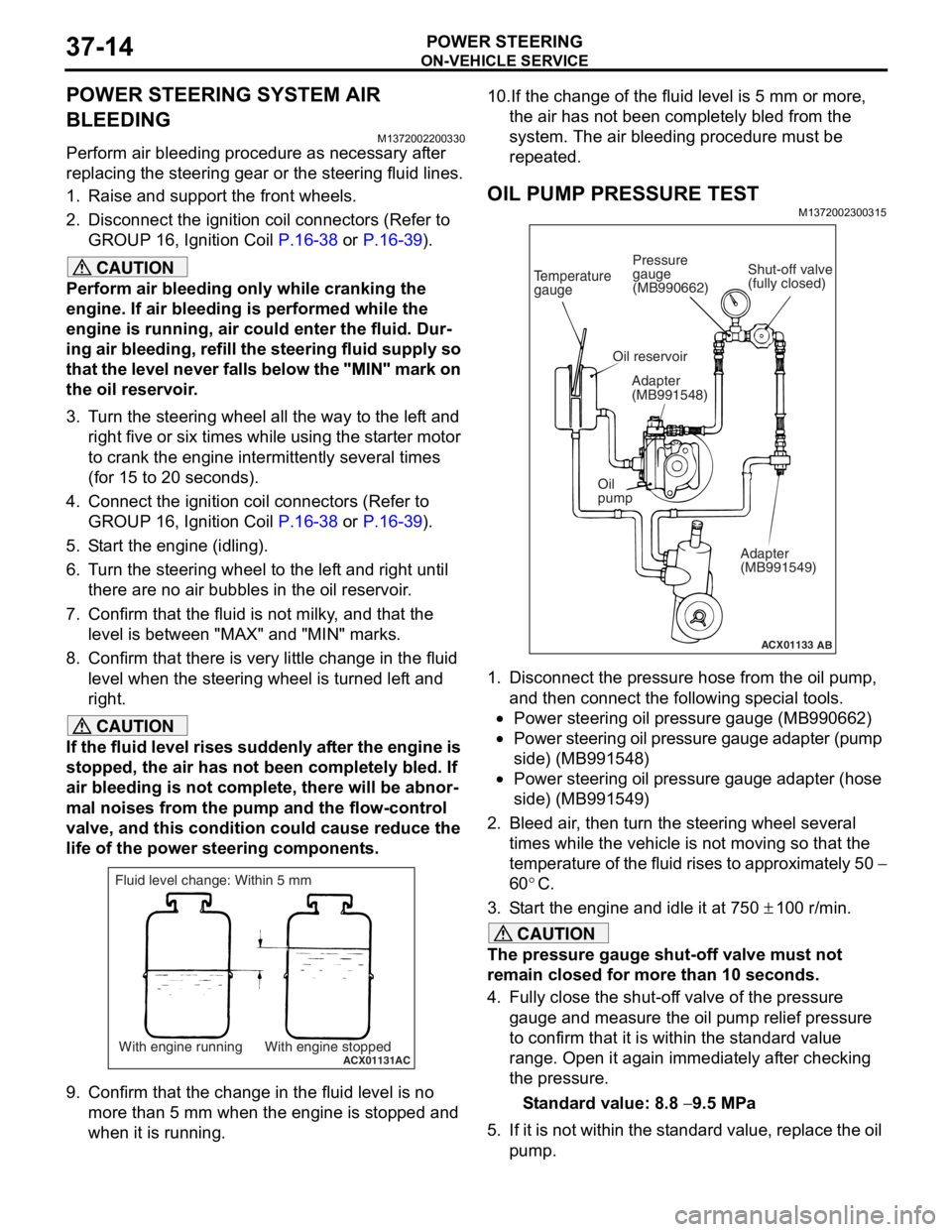
OIL PUMP PRESSURE TEST
M1372002300315
ACX01133
Temperature
gauge
Oil reservoir
Adapter
(MB991548)
Oil
pump Adapter
(MB991549)
AB
Shut-off valve
(fully closed)
Pressure
gauge
(MB990662)
1. Disconnect the pressure hose from the oil pump,
and then connect the following special tools.
•Power steering oil pressure gauge (MB990662)
•Power steering oil pressure gauge adapter (pump
side) (MB991548)
•Power steering oil pressure gauge adapter (hose
side) (MB991549)
2. Bleed air, then turn the steering wheel several times while the vehicle is not moving so that the
temperature of the fluid rises to approximately 50
−
60
°C.
3. Start the engine and idle it at 750 ± 100 r/min.
CAUTION
The pressure gauge shut-off valve must not
remain closed for more than 10 seconds.
4. Fully close the shut-off valve of the pressure gauge and measure the oil pump relief pressure
to confirm that it is within the standard value
range. Open it again immediately after checking
the pressure.
Standard value: 8.8 − 9.5 MPa
5. If it is not within the standard value, replace the oil pump.
Page 245 of 800
ON-VEHICLE SERVICE
POWER STEERING37-15
6. Check whether or not the hydraulic pressure is the standard value when no-load conditions are
created by fully opening the shut-off valve of the
pressure gauge.
Standard value: 0.2 − 0.7 MPa
7. If it is not within the standard value, the probable cause is a malfunction of the oil line or steering
gear, so check these parts and repair as
necessary.
8. Turn the steering wheel all the way to the left or right; then check whether or not the retention
hydraulic pressure is the standard value.
Standard value: 8.8 − 9.5 MPa
9. If not the standard value, overhaul the steering gear. Remeasure fluid pressure.
10. Remove the special tools, and then tighten the
pressure hose to the specified torque.
Tightening torque: 57 ± 7 N⋅m
11. Bleed the system (Refer to P.37-14).
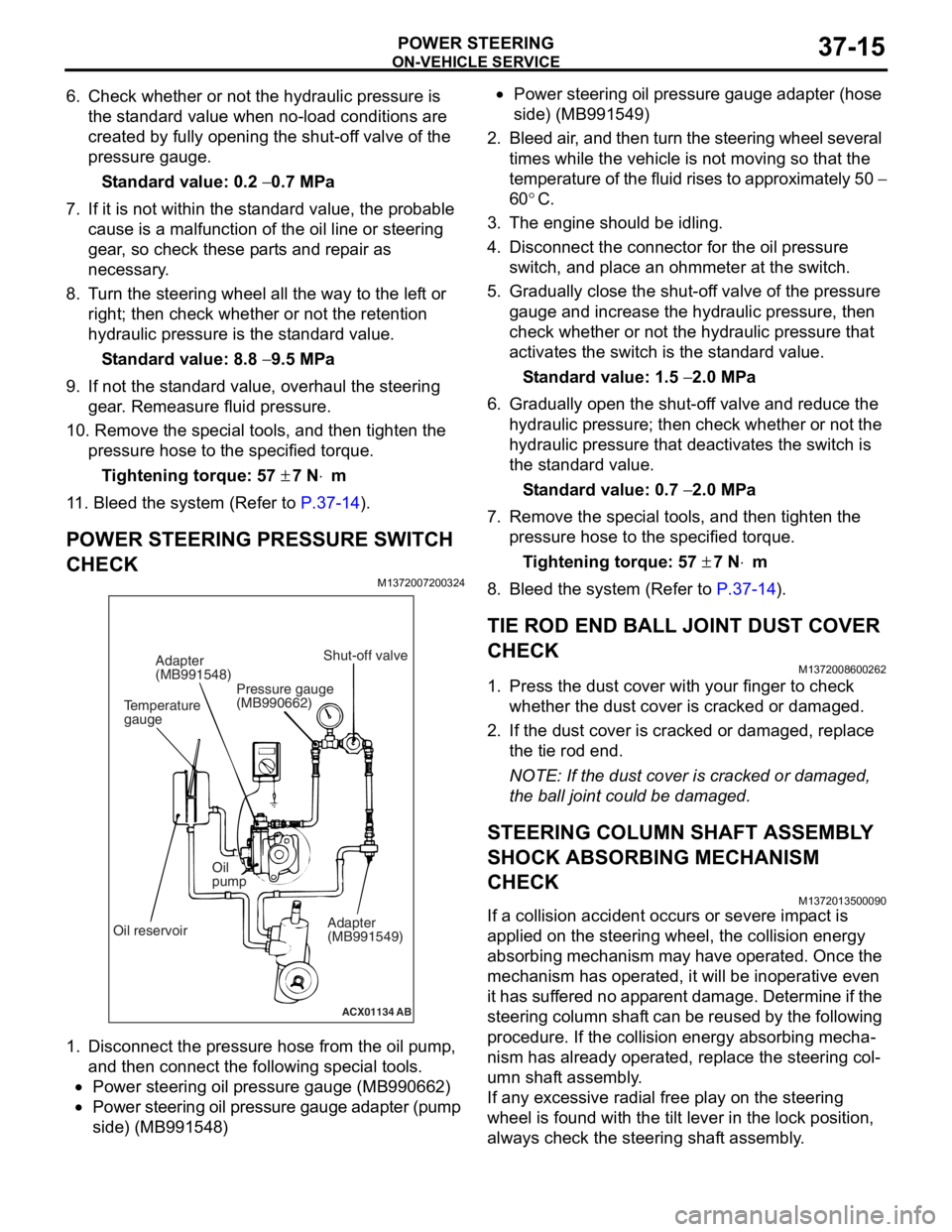
POWER STEERING PRESSURE SWITCH
CHECK
M1372007200324
ACX01134 AB
Temperature
gaugeAdapter
(MB991548)
Oil reservoir Oil
pump
Adapter
(MB991549)
Shut-off valve
Pressure gauge
(MB990662)
1. Disco nnect the pre s sure hose from the oil pump ,
an d then con nect the followin g sp ecial too l s.
•Power steering oil pressure gauge (MB990 662)
•Power steering oil pressure gauge ad apter (pump
side) (MB99154
8)
•Power steering oil pressure gaug e a dapte r (ho s e
side) (MB99154
9)
2. Bleed air , and the n turn t he steering wheel several
times while the vehicle is not moving so that the
tempe r atu r e o f th e flu i d rise s to approximately 50
−
60
°C.
3. Th e engine should be idling.
4.Disco nnect the conne ctor fo r the o il pr essure
switch , and p l ace an o h mmeter a t the switch .
5.Gradua lly close the shut-of f valve of the pressure
g auge a nd in crease the hyd r aulic pre ssu re, the n
check wheth e r or no t the h y drau lic pressure that
a c tivates the switch is the st a ndard valu e.
St andard va lue: 1.5 − 2.0 MPa
6.Gradua lly open the shut-of f va lve and re duce the
h y drau lic p r essure; then check whethe r o r n o t the
h y drau lic pressure that de activate s the switch is
th e st and ard va lue.
St andard va lue: 0.7 − 2.0 MPa
7.Remove the special tools, and then tighten the
p r essure hose to the specified torque .
Ti ghte n ing torque: 57 ± 7 N⋅m
8.Bleed the system (Refer to P.37-14).
TIE ROD END BALL JOINT DUST COVER
CHECK
M13720086 0026 2
1.Press th e dust co ver wit h you r fing er to check
whet her the dust cover is cra cke d or da mage d.
2.If the du st cover is cracked o r damaged, repla c e
th e tie rod end .
NOTE: If the dust cover is cra cke d or da mag ed,
th
e ball jo int could be da mage d.
STEERING COLUMN SHAFT ASSEMBL Y
SHOCK ABSORBING MECHANISM
CHECK
M13720135 0009 0
If a collision accid ent occu rs or seve re imp a ct is
applied on
the steering w heel, the collision energy
abso
r bing mechanism ma y h a ve opera t ed. Once the
mechanism
has o perate d , it will b e ino perative e v en
it has
suf f er ed no app a r en t d a mage . De termin e if the
steering colu
mn shaf t can b e reused b y th e following
proce
dure. If the collision en ergy a b sor b ing mecha
-
nism has already operated, rep l ace the steering col-
umn shaft assembly .
If any excessive radial fre e pla y on the steering
wh
eel is fo und with the tilt lever in the lock po sit i on,
always ch
eck the steering shaf t assembly .