suspension MITSUBISHI LANCER 2006 Workshop Manual
[x] Cancel search | Manufacturer: MITSUBISHI, Model Year: 2006, Model line: LANCER, Model: MITSUBISHI LANCER 2006Pages: 800, PDF Size: 45.03 MB
Page 137 of 800
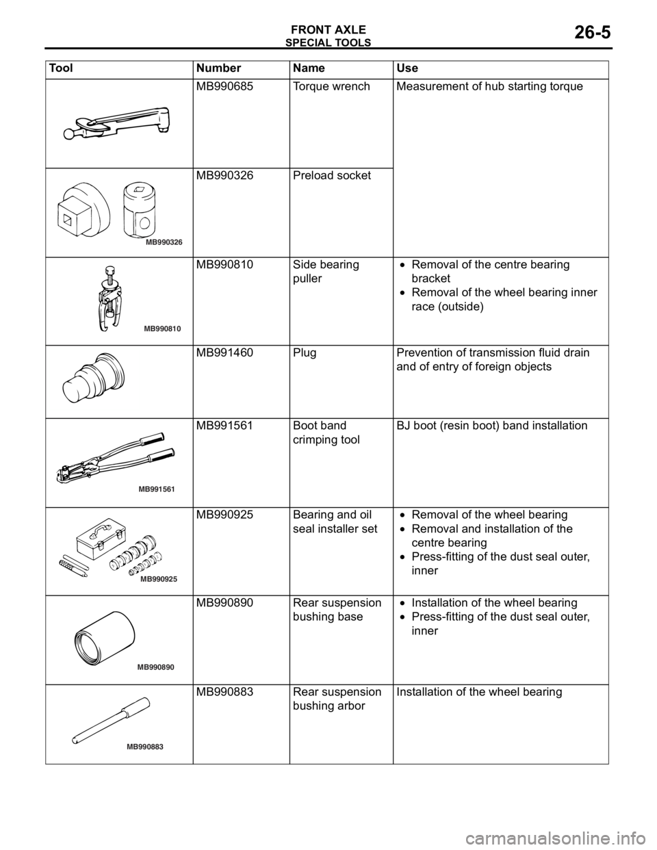
SPECIA L T OOLS
FRONT AXLE26-5
MB990685To rqu e wrenchMeas urement o f hub st arting torque
MB990326
MB990326 Prel oad socket
MB990810
MB990810Side be aring
puller•Removal of the centre b earing
bra
c ke t
•Removal of the whee l bea ring inner
r
a ce (o ut side )
MB991460PlugPreven tion of transmission fluid drain
and o
f entry of fore ign o b ject s
MB991561
MB991561Boot ban d
crimpin
g toolBJ boot (resin bo ot) ban d inst a lla tion
MB990925
MB990925Bearing and o il
seal
inst a lle r set•Removal of the whee l bea ring
•Removal and inst a lla tion o f the
centre
bearing
•Press-f i ttin g of th e dust se al ou ter ,
inner
MB990890
MB990890Rear suspension
bush
i ng b a se•In st allatio n of th e wheel bearing
•Press-f i ttin g of th e dust se al ou ter ,
inner
MB990883
MB990883Rear suspension
bush
i ng a r borInstallation of t he wheel bearing
Tool Nu mber Na me Use
Page 144 of 800
FRONT AXLE HUB ASSEMBLY
FRONT AXLE26-12
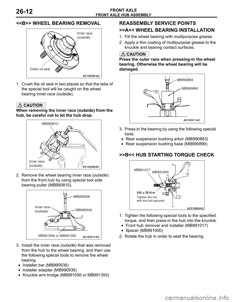
<> WHEEL BEARING REMOVAL
AC102508AC
Inner race
(outside)
Outer oil seal
1. Crush th e oil seal in two pl ace s so t hat t he t abs of
th e spe c ia l too l will be caugh t on th e wheel
be aring inne r race (out side).
CAUTION
When removing the inner race (outside) from the
hub, be careful not to let the hub drop.
AC102509
MB990810
Inner race
(outside)
AC
2. Remove the wheel bearing inner race (outside) from the front hub by using special tool side
bearing puller (MB990810).
AC102510 AC
MB990938
MB990935
MB991056 or MB991355
Inner race
(outside)
3. Install the inner race (outside) that was removed
from the hub to the wheel bearing, and then use
the following special tools to remove the wheel
bearing.
•Installer bar (MB990938)
•Installer adapter (MB990935)
•Knuckle arm bridge (MB991056 or MB991355)
REASSEMBLY SERVICE POINTS
>>A<< WHEEL BEARING INSTALLATION
1. Fill the wheel bearing with multipurpose grease.
2. Apply a thin coating of multipurpose grease to the knuckle and bearing contact surfaces.
CAUTION
Press the outer race when pressing-in the wheel
bearing. Otherwise the wheel bearing will be
damaged.
AC102511
MB990883
MB990890
AC
3. Press-in the bearing by using the following special tools.
•Rear suspension bushing arbor (MB990883)
•Rear suspension bushing base (MB990890)
>>B<< HUB STARTING TORQUE CHECK
AC210929AC
MB991000
MB991017
245 ± 29 N·m
Tighten the nut
with the bolt secured
1. Tighten the following special tools to the specified torque, and then press-in the hub into the knuckle.
•Front hub remover and installer (MB991017)
•Spacer (MB991000)
2. Rotate the hub in order to seat the bearing.
Page 166 of 800
TROUBLESHOOTING
WHEEL AND TYRE31-4
WHEEL BALANCE ACCURACY
M1311001700247
PURPOSE
This section contains tips and procedures for achiev-
ing accurate wheel balance. Steering wheel vibration
and/or body shake can result if any of these proce
-
dures are not carefully observed.
1. Wheels and tyres must be properly mounted on a balancer in order to achieve correct balance.
Centring the wheel on the shaft of the balancer is
essential for proper mounting.
2. Off-the-car wheel balancers must be calibrated periodically to ensure good balancing results. An
inaccurately calibrated balancer could cause
unnecessary replacement of tyres, shocks,
suspension components, or steering components.
Check your balancer's calibration approximately
every 100 balances. Your wheel balancer's instruc
-
tion manual should include calibration procedures. If
the calibration procedures specifically for your bal
-
ancer are missing, use the generic steps in this sec-
tion for zero calibration, static balance, and dynamic
balance checks. The wheel balancer calibration
checks are also described in the flowchart. (Refer to
P.31-6).
PROCEDURE
1. Confirm that the balancer's cone and the wheel
mounting cone are undamaged and free of dirt
and rust.
2. On this vehicle, the wheel's centre hole on the hub side has a chamfered edge. Use a
back-mounting cone on your wheel balancer to
centre the wheel on the balancer shaft.
3. Install a wheel mounting cone. The appropriate size cone for this vehicle is 67.0 mm.
4. Before balancing the wheel, remove any wheel weights from both sides. Also check both sides for
any damage.
5. When installing wheel weights, hammer them at a straight (not diagonal) angle.
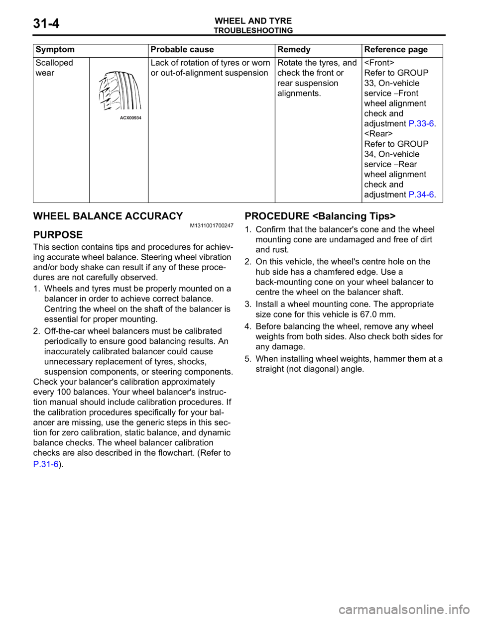
Scalloped
wear
ACX00934
Lack of rot a tio n of tyres or worn
or out-of-a
lign m ent suspensionRota te th e tyre s, an d
check the f
r ont or
rea
r suspension
alignment
s.
Refer to GROUP
33
, On -vehicle
serv
ic e
− Front
whee
l alignment
check and
ad
justmen t
P.33-6.
Refer to GROUP
34
, On -vehicle
serv
ic e
− Rear
whee
l alignment
check and
ad
justmen t
P.34-6.
Sy mptom P robable cause Reme dy Referen ce p a g e
Page 172 of 800
GENERAL INFORMATION
POWER PLANT MOUNT32-2
GENERAL INFORMATION
M1321000100340
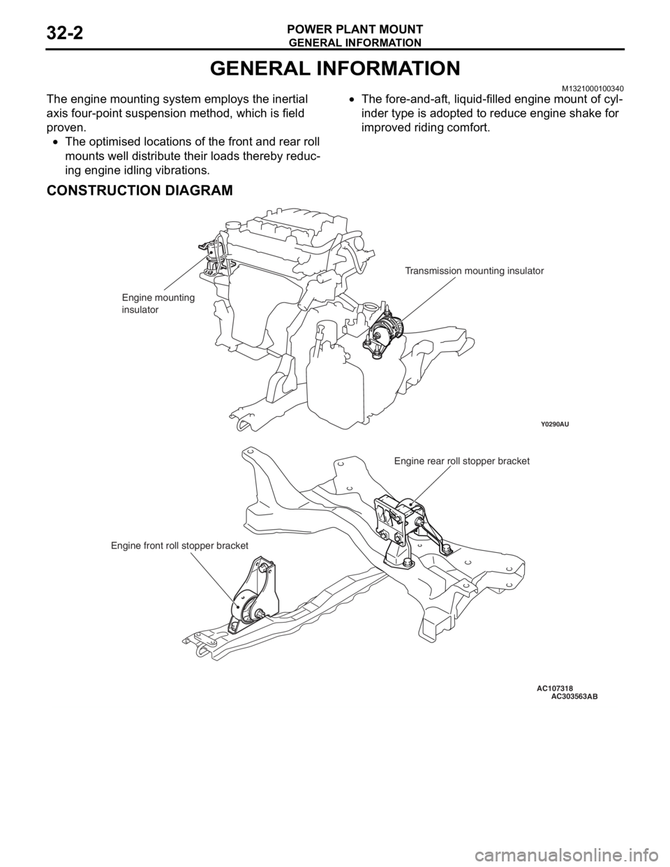
The engine mounting system employs the inertial
axis four-point suspension method, which is field
proven.
•The optimised locations of the front and rear roll
mounts well distribute their loads thereby reduc
-
ing engine idling vibrations.
•The fore-and-aft, liquid-filled engine mount of cyl-
inder type is adopted to reduce engine shake for
improved riding comfort.
CONSTRUCTION DIAGRAM
AC107318
Y0290AU
AC303563
Engine mounting
insulatorTransmission mounting insulator
Engine rear roll stopper bracket
Engine front roll stopper bracket
AB
Page 183 of 800
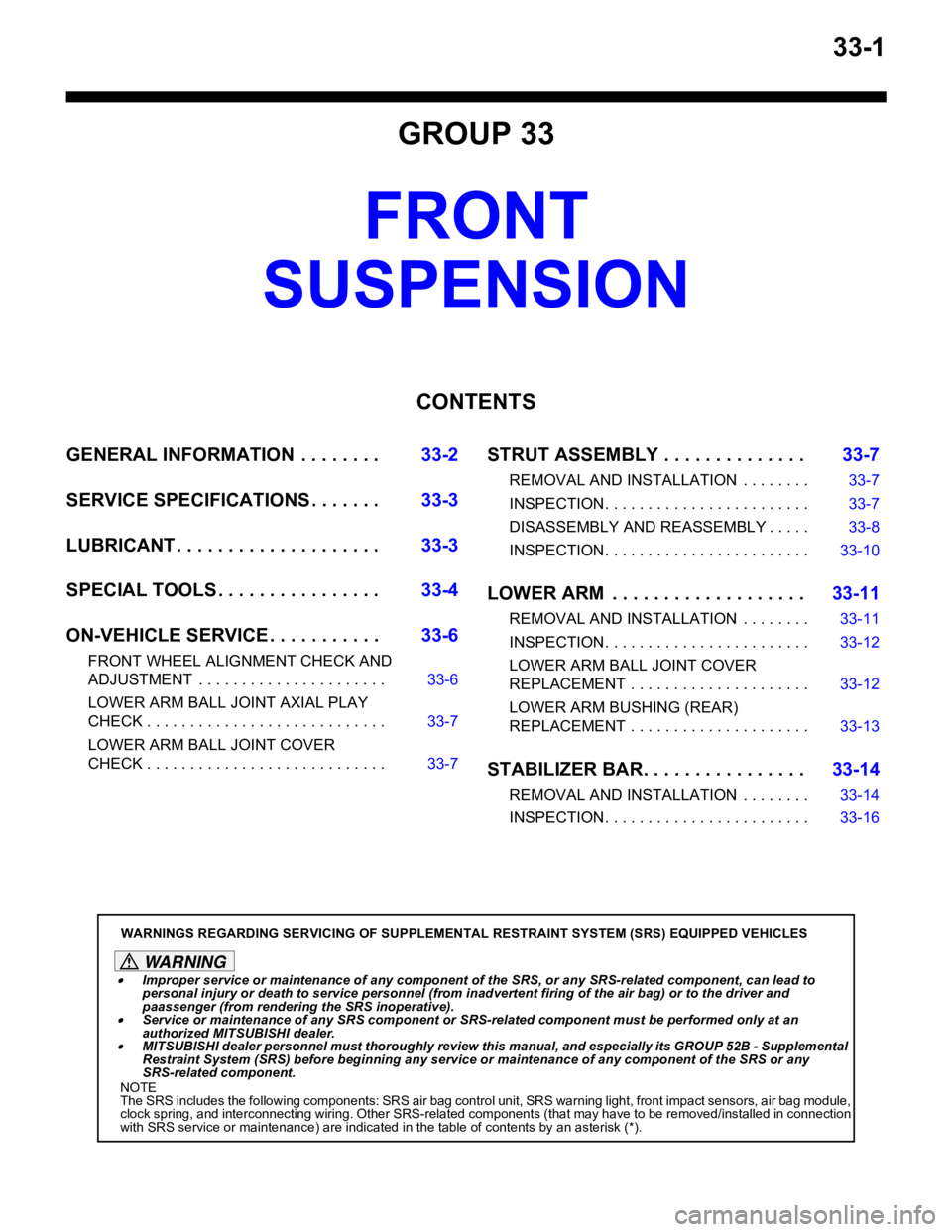
33-1
GROUP 33
FRONT
SUSPENSION
CONTENTS
GENERAL INFORMATIO N . . . . . . . .33-2
SERVICE SPECIFICATIONS . . . . . . .33-3
LUBRICANT . . . . . . . . . . . . . . . . . . . .33-3
SPECIAL TOOLS . . . . . . . . . . . . . . . .33-4
ON-VEHICLE SERVICE . . . . . . . . . . .33-6
FRONT WHEEL ALIGNMENT CHECK AND
ADJUSTMENT . . . . . . . . . . . . . . . . . . . . . . 33-6
LOWER ARM BALL JOINT AXIAL PLAY
CHECK . . . . . . . . . . . . . . . . . . . . . . . . . . . . 33-7
LOWER ARM BALL JOINT COVER
CHECK . . . . . . . . . . . . . . . . . . . . . . . . . . . . 33-7
STRUT ASSEMBLY . . . . . . . . . . . . . .33-7
REMOVAL AND INSTALLATION . . . . . . . . 33-7
INSPECTION. . . . . . . . . . . . . . . . . . . . . . . . 33-7
DISASSEMBLY AND REASSEMBLY . . . . . 33-8
INSPECTION. . . . . . . . . . . . . . . . . . . . . . . . 33-10
LOWER ARM . . . . . . . . . . . . . . . . . . .33-11
REMOVAL AND INSTALLATION . . . . . . . . 33-11
INSPECTION. . . . . . . . . . . . . . . . . . . . . . . . 33-12
LOWER ARM BALL JOINT COVER
REPLACEMENT . . . . . . . . . . . . . . . . . . . . . 33-12
LOWER ARM BUSHING (REAR)
REPLACEMENT . . . . . . . . . . . . . . . . . . . . . 33-13
STABILIZER BAR. . . . . . . . . . . . . . . .33-14
REMOVAL AND INSTALLATION . . . . . . . . 33-14
INSPECTION. . . . . . . . . . . . . . . . . . . . . . . . 33-16
WARNINGS REGARDING SERVICING OF SUPPLEMENTAL RESTRAINT SYSTEM (SRS) EQUIPPED VEHICLES
WARNING
•Improper service or maintenance of any component of the SRS, or any SRS-related component, can lead to
personal injury or death to service personnel (from inad vertent firing of the air bag) or to the driver and
paassenger (from rendering the SRS inoperative).
•Service or maintenance of any SRS component or SRS-related component must be performed only at an
authorized MITSUBISHI dealer.
•MITSUBISHI dealer personnel must thoroughly review this manual, and especially its GROUP 52B - Supplemental
Restraint System (SRS) before beginning any service or maintenance of any component of the SRS or any
SRS-related component.
NOTE
The SRS includes the following components: SRS air bag control unit, SRS warning light, front impact sensors, air bag module,
clock spring, and interconnecting wiring. Other SRS-related components (that may have to be removed/installed in connection
with SRS service or maintenance) are indicated in the table of contents by an asterisk (*).
Page 184 of 800
GENERAL INFORMATION
FRONT SUSPENSION33-2
GENERAL INFORMATION
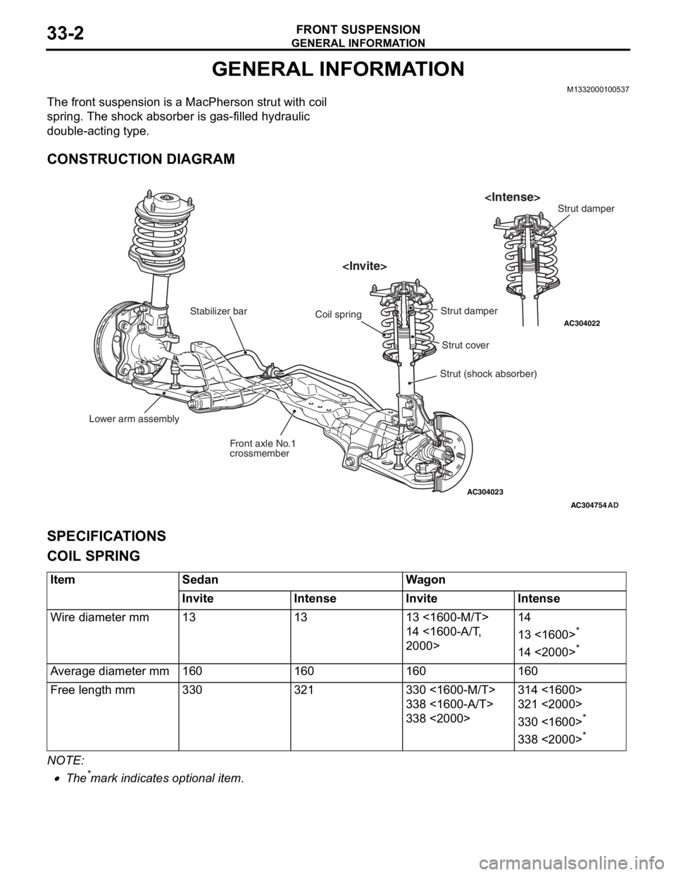
M1332000100537
The front suspension is a MacPherson strut with coil
spring. The shock absorber is gas-filled hydraulic
double-acting type.
CONSTRUCTION DIAGRAM
AC304023
AC304022
AC304754
Lower arm assembly Front axle No.1
crossmember
Stabilizer bar
Strut (shock absorber)
Coil spring
AD
Strut cover
Strut damper
SPECIFICA
T IONS
COIL SPRING
ItemSedanWagon
InviteIntenseInviteIntense
Wire diameter mm131313 <1600-M/T>
14 <1600-A/T,
2000>
14
13 <1600>*
14 <2000>*
Average diameter mm160160160160
Free length mm330321330 <1600-M/T>
338 <1600-A/T>
338 <2000>
314 <1600>
321 <2000>
330 <1600>*
338 <2000>*
NOTE: .
•The*mark indicat e s op tiona l it em.
Page 185 of 800
SERVICE SPECIFICATIONS
FRONT SUSPENSION33-3
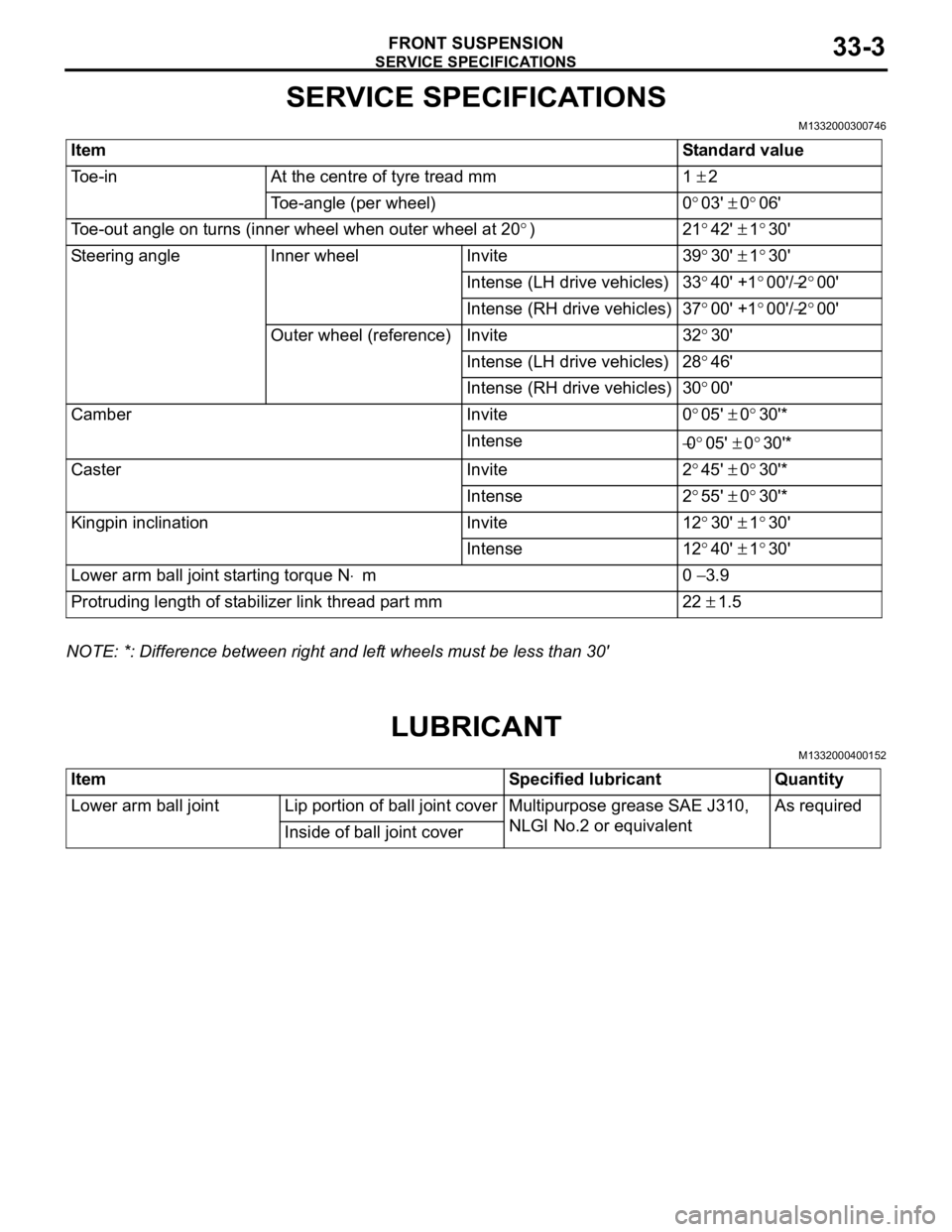
SERVICE SPECIFICATIONS
M1332000300746
ItemStandard value
Toe-inAt the centre of tyre tread mm1 ± 2
Toe-angle (per wheel)0°03' ± 0°06'
Toe-out angle on turns (inner wheel when outer wheel at 20°)21°42' ± 1°30'
Steering angleInner wheelInvite39°30' ± 1°30'
Intense (LH drive vehicles)33°40' +1°00'/−2°00'
Intense (RH drive vehicles)37°00' +1°00'/−2°00'
Outer wheel (reference)Invite32°30'
Intense (LH drive vehicles)28°46'
Intense (RH drive vehicles)30°00'
CamberInvite0°05' ± 0°30'*
Intense−0°05' ± 0°30'*
CasterInvite2°45' ± 0°30'*
Intense2°55' ± 0°30'*
Kingpin inclinationInvite12°30' ± 1°30'
Intense12°40' ± 1°30'
Lower arm ball joint starting torque N⋅m0 − 3.9
Protruding length of stabilizer link thread part mm22 ± 1.5
NOTE: *: Difference between right and left wheels must be less than 30'
LUBRICANT
M1332000400152
ItemSpecified lubricantQuantity
Lower arm ball jointLip portion of ball joint coverMultipurpose grease SAE J310,
NLGI No.2 or equivalentAs required
Inside of ball joint cover
Page 186 of 800
SPECIAL TOOLS
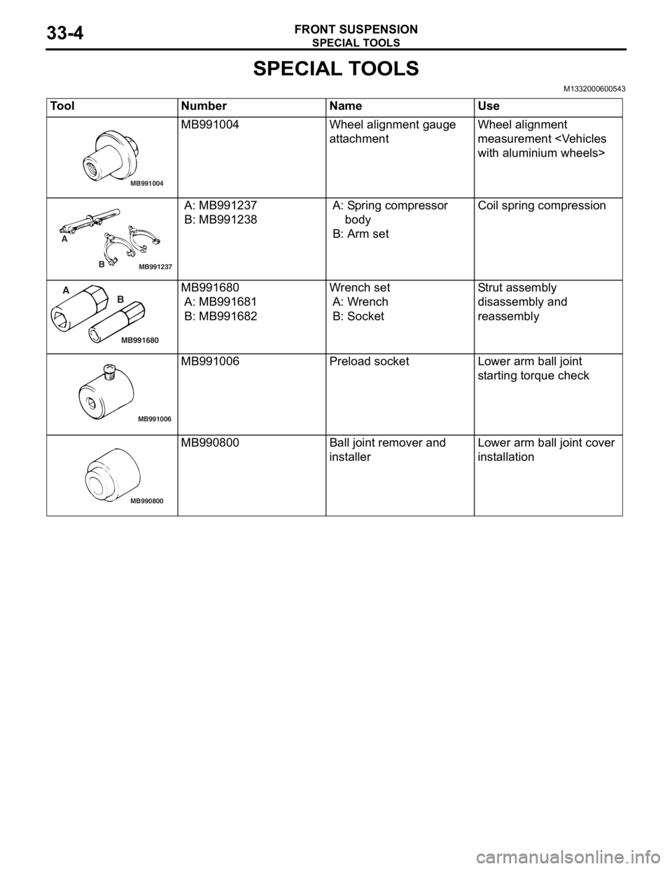
FRONT SUSPENSION33-4
SPECIAL TOOLS
M1332000600543
ToolNumberNameUse
MB991004
MB991004Wheel alignme n t gau ge
att
a chmentWheel alig nme n t
measurement
with aluminium wheels>
MB991237
A
B
A: MB9912 37
B: MB991238
A: Sp ring compressor
b ody
B: Arm set
Coil spring compression
MB991680
A BMB991680
A: MB9916 81
B: MB991682
Wr ench set
A: W r ench
B: Socket
Str u t a s s e m b l y
d
i sa ssembly an d
reassembly
MB991006
MB991006Prel oad socketLo wer arm ball joint
st
arting torque check
MB990800
MB990800Ball j o int remo ver an d
inst
al lerLo wer arm ball joint cover
inst
allation
Page 187 of 800
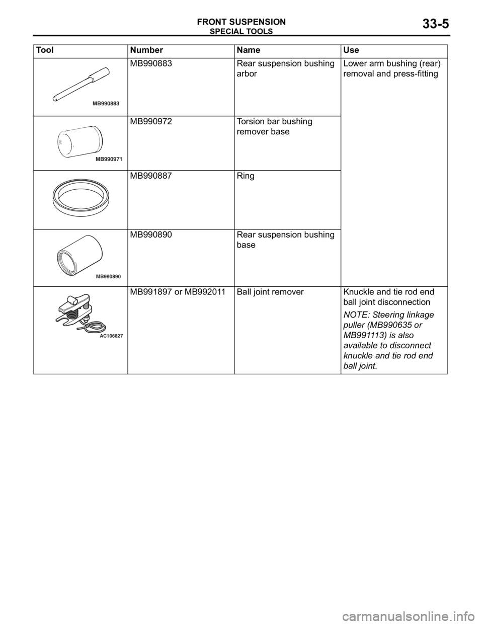
MB990883
SPECIA L T OOLS
FRONT SU SPENSION33-5
MB990883Rear suspension bushing
arborLo wer arm bushing (rear)
re
moval a nd press-fittin g
MB990971
MB990972To rsion b a r bushin g
remover base
MB990887Ring
MB990890
MB990 890Rear suspension bushing
base
AC106827
MB991897 or MB9920 1 1Ball j o int remo verKnuckle an d tie rod end
b
a ll joint disco nnection
NOTE: St eering linka ge
p
u
ller (MB99 0635 o r
MB991
1 13) is also
a
v
ailable to d i sconne ct
knuckle and t i e rod end
b
a
ll
joi
n t.
T ool Nu mber Na me Use
Page 188 of 800
ON-VEHICLE SERVICE
FRONT SUSPENSION33-6
ON-VEHICLE SERVICE
FRONT WHEEL ALIGNMENT CHECK AND
ADJUSTMENT
M1331000900886
Measure wheel alignment with alignment equipment
on a level surface. The front suspension, steering
system, wheels, and tyres should be serviced to nor
-
mal condition before measuring wheel alignment.
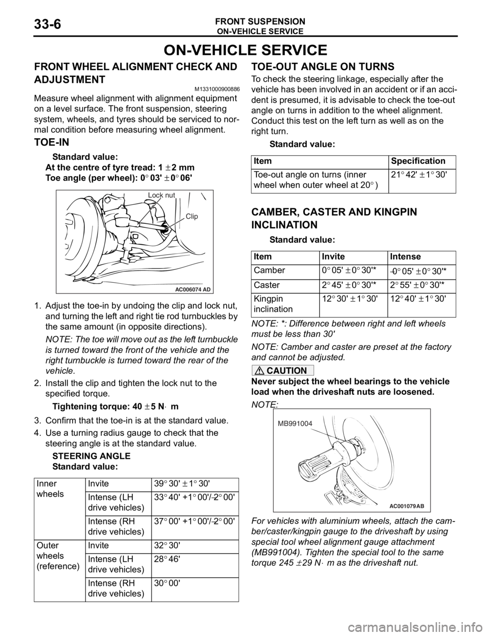
TOE-IN
Standard value:
At the centre of tyre tread: 1 ± 2 mm
Toe angle (per wheel): 0°03' ± 0°06'
AC006074 AD
Lock nut
Clip
1.Adjust the to e-in by undoing th e clip and lock nut,
and turning th e lef t and rig h t tie rod turnbu ckles by
th e same amount (in op posite direct ions).
NOTE: The toe will move out as th e lef t turnbuckle
is turn
ed toward the fro n t of th e ve hicle an d the
right tu
rnbuckle is turned t o ward the rear of the
vehicle.
2. In st all the clip and tighten the lock nut to the
specifie d torqu e .
Ti ghte n ing torque: 40 ± 5 N⋅m
3.Conf irm t hat the toe-in is at the st anda rd value.
4.Use a turn ing ra dius gaug e to check tha t the
steering ang le is at the st an dard value .
STEE R I N G AN G L E
St andard va lue:
Inner
wheelsInvite39°30' ± 1°30'
Intense (LH
drive vehicles)33°40' +1°00'/−2°00'
Intense (RH
drive vehicles)37°00' +1°00'/−2°00'
Outer
wheels
(reference)Invite32°30'
Intense (LH
drive vehicles)28°46'
Intense (RH
drive vehicles)30°00'
TO E-OUT ANGLE ON TURNS
To check the stee ring linkage, e s pe cially af ter the
vehicle has been invo
lve d in an accid ent or if an a cci
-
dent is pres umed, it is advisab le to check th e toe-ou t
angle
on tu rns in addition to the wh eel a lig nmen t.
Conduct this test on th e lef t tu rn as we ll a s on the
right turn.
St andard va lue:
ItemSpecification
Toe-out angle on turns (inner
wheel when outer wheel at 20
°)
21°42' ± 1°30'
CAMBER, CASTER AND KINGPIN
INCLINA
T ION
St andard va lue:
ItemInviteIntense
Camber0°05' ± 0°30'*−0°05' ± 0°30'*
Caster2°45' ± 0°30'*2°55' ± 0°30'*
Kingpin
inclination12°30' ± 1°30'12°40' ± 1°30'
NOTE: *: Diffe rence between right and lef t wheels
must be less than 30'
NOTE: Camber and caster are prese t at th e factory
and cannot be adjust ed.
CAUTION
Never subject the wheel bearings to the vehicle
load when the driveshaft nuts are loosened.
NOTE:
AC001079
MB991004
AB
For vehicles with aluminium wheels, attach the cam-
ber/caster/kingpin gauge to the driveshaft by using
special tool wheel alignment gauge attachment
(MB991004). Tighten the special tool to the same
torque 245
± 29 N⋅m as the driveshaft nut.