Starting MITSUBISHI LANCER 2006 User Guide
[x] Cancel search | Manufacturer: MITSUBISHI, Model Year: 2006, Model line: LANCER, Model: MITSUBISHI LANCER 2006Pages: 800, PDF Size: 45.03 MB
Page 91 of 800
AK202734
STARTING SYSTEM
ENGINE ELECTRICAL16-29
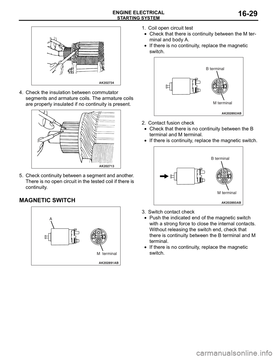
4. Check t he in sulation between commut ator
segment s an d arma ture coils. Th e armature coils
are prope rly insu lated if no con t inuity is pre s ent .
AK202713
5. Check continuit y bet ween a segment and another .
Th ere is n o ope n circui t in th e t e s t e d c o il if t h e r e is
continuity .
MA GNETIC SW ITCH
AK202891
A
M terminal
AB
1.Coil ope n circuit test
•Check that there is continuity be twe en the M te r-
minal and body A.
•
AK202892
M terminal
B terminal
AB
If th
ere is no continuit y , replace t he ma gnetic
sw
itc h .
2.Cont act fusion check
•Check that there is no co ntinu i ty between the B
termina
l and M te rmin al.
•
AK202893
M terminal
B terminal
AB
If th
ere is co ntinu i ty , re place the magn etic switch.
3.Switch cont act check
•Push the indicated end o f the magne tic switch
with
a stro ng force to close th e inte rnal cont act s .
Without re
leasing the switch end, check tha t
the
r e is con t inuity b e tween th e B terminal and M
termina
l .
•If there is no continuit y , replace t he ma gnetic
sw
itc h .
Page 135 of 800
SERVICE SPECIFICATIONS
FRONT AXLE26-3
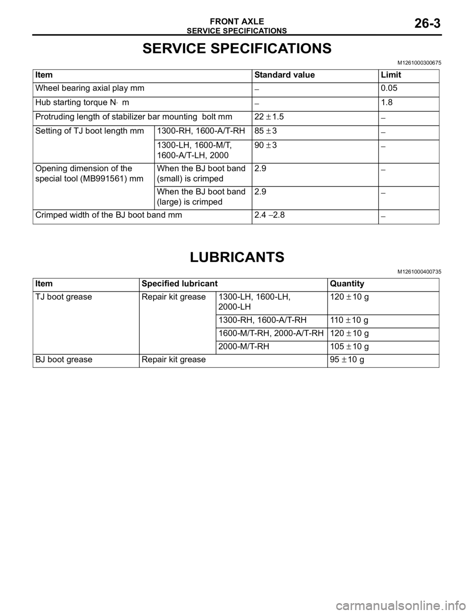
SERVICE SPECIFICATIONS
M1261000300675
ItemStandard valueLimit
Wheel bearing axial play mm−0.05
Hub starting torque N⋅m−1.8
Protruding length of stabilizer bar mounting bolt mm22 ± 1.5−
Setting of TJ boot length mm1300-RH, 1600-A/T-RH85 ± 3−
1300-LH, 1600-M/T,
1600-A/T-LH, 200090 ± 3−
Opening dimension of the
special tool (MB991561) mmWhen the BJ boot band
(small) is crimped2.9−
When the BJ boot band
(large) is crimped2.9 −
Crimped width of the BJ boot band mm2.4 − 2.8−
LUBRICANTS
M1261000400735
ItemSpecified lubricantQuantity
TJ boot greaseRepair kit grease1300-LH, 1600-LH,
2000-LH120 ± 10 g
1300-RH, 1600-A/T-RH11 0 ± 10 g
1600-M/T-RH, 2000-A/T-RH120 ± 10 g
2000-M/T-RH105 ± 10 g
BJ boot greaseRepair kit grease95 ± 10 g
Page 143 of 800
FRONT AXLE HUB ASSEMBLY
FRONT AXLE26-11
INSPECTION
M1261001800242
•Check the hub for cracks and spline for wear.
•Check the knuckle for cracks.
•Check for defective bearing.
NOTE: If the meshing of the wheel bearing outer
race and the knuckle, or of the wheel bearing
inner race and the hub, is loose, replace the
bearing or damaged parts.
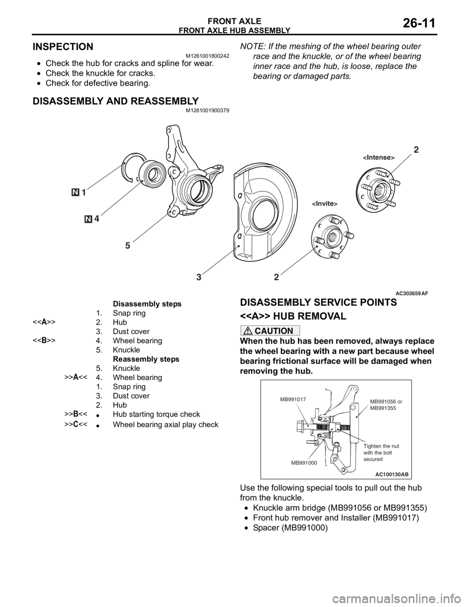
DISASSEMBLY AND REASSEMBLY
M1261001900379
AC303659
N
N4
1
5 3 2
AF
2
Disassembly steps
1.Snap ring
<>2.Hub
3.Dust cover
<>4.Wheel bearing
5.Knuckle
Reassembly steps
5.Knuckle
>>A<<4.Wheel bearing
1.Snap ring
3.Dust cover
2.Hub
>>B<<•Hub starting torque check
>>C<<•Wheel bearing axial play check
DISASSEMBL
Y SER V ICE POINTS
< > HUB REMOV A L
CAUTION
When the hub has been removed, always replace
the wheel bearing with a new part because wheel
bearing frictional surface will be damaged when
removing the hub.
AC100130
Tighten the nut
with the bolt
secured MB991056 or
MB991355
MB991017
MB991000 AB
Use the following special tools to pull out the hub
from the knuckle.
•Knuckle arm bridge (MB991056 or MB991355)
•Front hub remover and Installer (MB991017)
•Spacer (MB991000)
Page 144 of 800
FRONT AXLE HUB ASSEMBLY
FRONT AXLE26-12
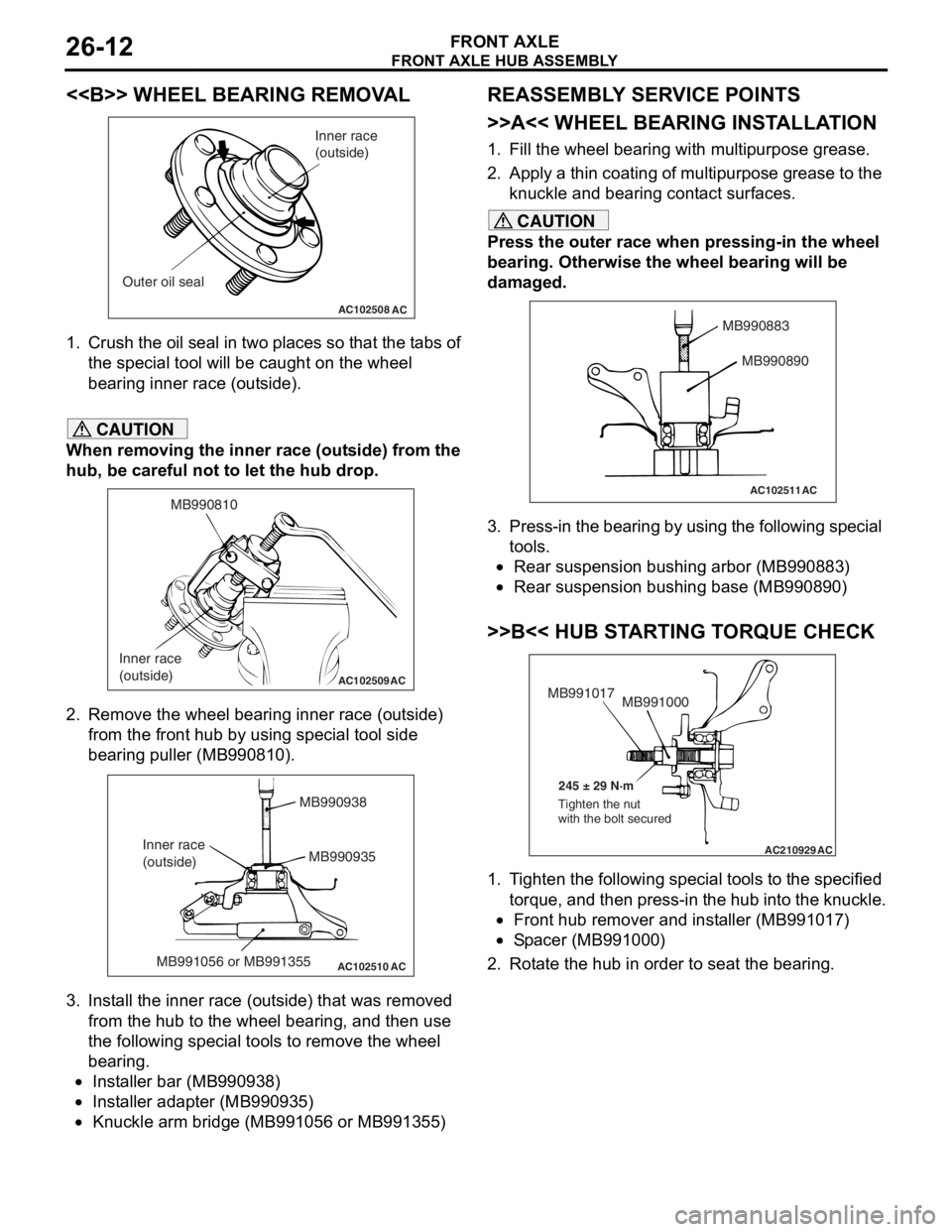
<> WHEEL BEARING REMOVAL
AC102508AC
Inner race
(outside)
Outer oil seal
1. Crush th e oil seal in two pl ace s so t hat t he t abs of
th e spe c ia l too l will be caugh t on th e wheel
be aring inne r race (out side).
CAUTION
When removing the inner race (outside) from the
hub, be careful not to let the hub drop.
AC102509
MB990810
Inner race
(outside)
AC
2. Remove the wheel bearing inner race (outside) from the front hub by using special tool side
bearing puller (MB990810).
AC102510 AC
MB990938
MB990935
MB991056 or MB991355
Inner race
(outside)
3. Install the inner race (outside) that was removed
from the hub to the wheel bearing, and then use
the following special tools to remove the wheel
bearing.
•Installer bar (MB990938)
•Installer adapter (MB990935)
•Knuckle arm bridge (MB991056 or MB991355)
REASSEMBLY SERVICE POINTS
>>A<< WHEEL BEARING INSTALLATION
1. Fill the wheel bearing with multipurpose grease.
2. Apply a thin coating of multipurpose grease to the knuckle and bearing contact surfaces.
CAUTION
Press the outer race when pressing-in the wheel
bearing. Otherwise the wheel bearing will be
damaged.
AC102511
MB990883
MB990890
AC
3. Press-in the bearing by using the following special tools.
•Rear suspension bushing arbor (MB990883)
•Rear suspension bushing base (MB990890)
>>B<< HUB STARTING TORQUE CHECK
AC210929AC
MB991000
MB991017
245 ± 29 N·m
Tighten the nut
with the bolt secured
1. Tighten the following special tools to the specified torque, and then press-in the hub into the knuckle.
•Front hub remover and installer (MB991017)
•Spacer (MB991000)
2. Rotate the hub in order to seat the bearing.
Page 185 of 800
SERVICE SPECIFICATIONS
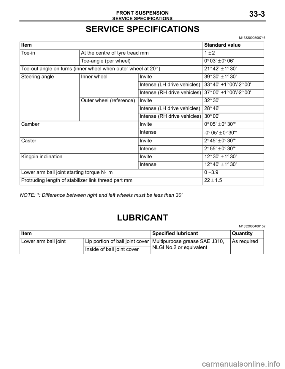
FRONT SUSPENSION33-3
SERVICE SPECIFICATIONS
M1332000300746
ItemStandard value
Toe-inAt the centre of tyre tread mm1 ± 2
Toe-angle (per wheel)0°03' ± 0°06'
Toe-out angle on turns (inner wheel when outer wheel at 20°)21°42' ± 1°30'
Steering angleInner wheelInvite39°30' ± 1°30'
Intense (LH drive vehicles)33°40' +1°00'/−2°00'
Intense (RH drive vehicles)37°00' +1°00'/−2°00'
Outer wheel (reference)Invite32°30'
Intense (LH drive vehicles)28°46'
Intense (RH drive vehicles)30°00'
CamberInvite0°05' ± 0°30'*
Intense−0°05' ± 0°30'*
CasterInvite2°45' ± 0°30'*
Intense2°55' ± 0°30'*
Kingpin inclinationInvite12°30' ± 1°30'
Intense12°40' ± 1°30'
Lower arm ball joint starting torque N⋅m0 − 3.9
Protruding length of stabilizer link thread part mm22 ± 1.5
NOTE: *: Difference between right and left wheels must be less than 30'
LUBRICANT
M1332000400152
ItemSpecified lubricantQuantity
Lower arm ball jointLip portion of ball joint coverMultipurpose grease SAE J310,
NLGI No.2 or equivalentAs required
Inside of ball joint cover
Page 201 of 800
SERVICE SPECIFICATIONS
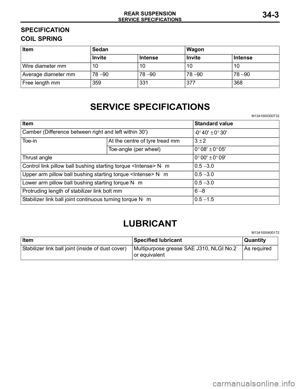
REAR SUSPENSION34-3
SPECIFICATION
COIL SPRING
ItemSedanWagon
InviteIntenseInviteIntense
Wire diameter mm10101010
Average diameter mm78 − 9078 − 9078 − 9078 − 90
Free length mm359331377368
SERVICE SPECIFICATIONS
M1341000300733
ItemStandard value
Camber (Difference between right and left within 30') −0°40' ± 0°30'
Toe-inAt the centre of tyre tread mm3 ± 2
Toe-angle (per wheel)0°08' ± 0°05'
Thrust angle0°00' ± 0°09'
Control link pillow ball bushing starting torque
Upper arm pillow ball bushing starting torque
Lower arm pillow ball bushing starting torque N⋅m0.5 − 3.0
Protruding length of stabilizer link bolt mm6 − 8
Stabilizer link ball joint continuous turning torque N⋅m0.5 − 1.5
LUBRICANT
M1341000400172
ItemSpecified lubricantQuantity
Stabilizer link ball joint (inside of dust cover)Multipurpose grease SAE J310, NLGI No.2
or equivalentAs required
Page 208 of 800
CONTROL LINK, UPPER ARM AND LOWER ARM
REAR SUSPENSION34-10
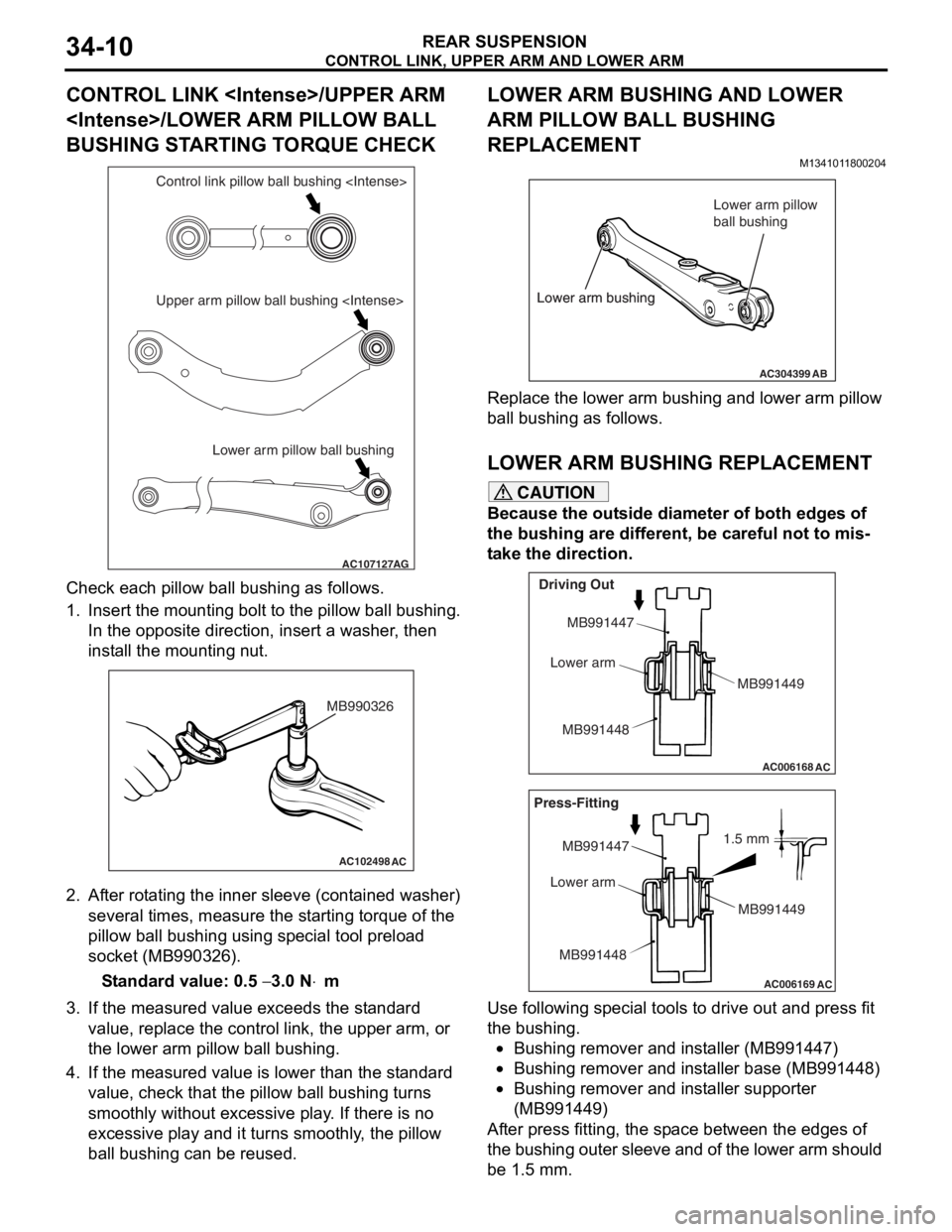
CONTROL LINK
BUSHING STARTING TORQUE CHECK
AC107127AG
Lower arm pillow ball bushing
Upper arm pillow ball bushing
Che
c k each pillow ball bu shing as follows.
1.In sert the mou n ting bo lt t o th e pillo w ball b u shing.
In the op posite direction, inse rt a wash er , the n
inst all the moun ting n u t.
AC102498AC
MB990326
2.Af ter rot a ting the inner sleeve (cont aine d washer)
seve ral times, me asure the st a r ting torque o f the
pillow ball bushing using sp ecial to ol pre l oad
socket (MB990326 ).
St andard va lue: 0.5 − 3.0 N⋅m
3.If the measu r ed value exceeds the st a ndard
value , replace the control lin k, the upper arm, o r
th e lower a r m pillo w ball bushing.
4.If the measu r ed value is lower tha n the st andard
value , che c k that th e pillow ba ll b u shing turn s
smoo thly withou t excessive play . If the r e is no
exce ssive play and it turns smooth l y , the pillow
ba ll b u shing can be reused.
LOWER ARM BUSHING AND LOWER
ARM PILLOW BALL BUSHING
REPLACEMENT
M134101 18 0020 4
AC304399AB
Lower arm bushing Lower arm pillow
ball bushing
Lower arm bushing
Re place the lower a r m bu shing an d lower arm p illow
ball bushing
as fo llows.
LO WER ARM BUSHING REPLACEM ENT
CAUTION
Because the outside diameter of both edges of
the bushing are different, be careful not to mis
-
take the direction.
AC006168
AC
Driving Out
MB991447
Lower arm
MB991448 MB991449
AC006169
AC
1.5 mm
Press-Fitting
MB991447
Lower arm
MB991448 MB991449
Use following special tools to drive out and press fit
the bushing.
•Bushing remover and installer (MB991447)
•Bushing remover and installer base (MB991448)
•Bushing remover and installer supporter
(MB991449)
After press fitting, the space between the edges of
the bushing outer sleeve and of the lower arm should
be 1.5 mm.
Page 286 of 800
WINDOW GLASS
BODY42-14
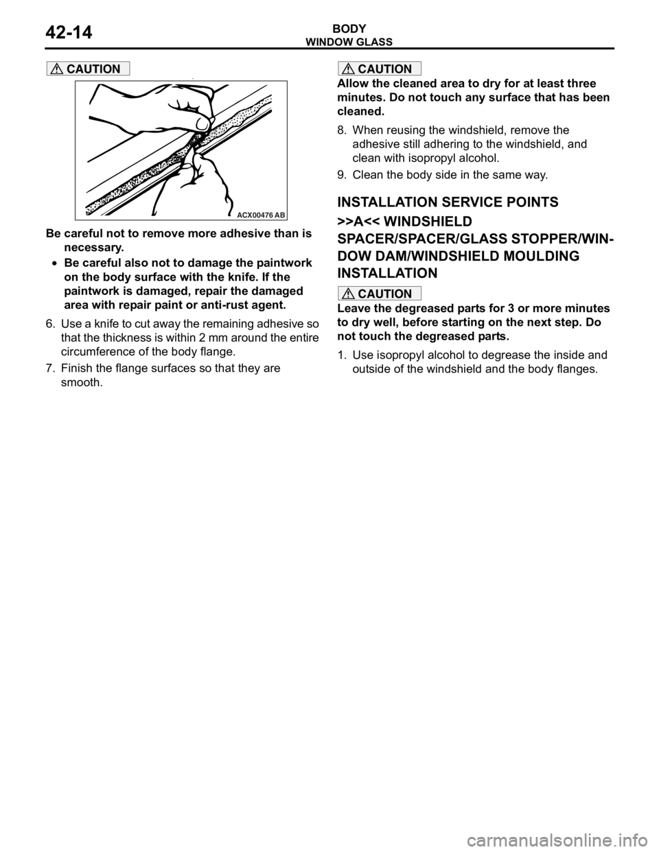
CAUTION•
ACX00476AB
Be careful not to remove more adhesive than is
necessary.
•Be careful also not to damage the paintwork
on the body surface with the knife. If the
paintwork is damaged, repair the damaged
area with repair paint or anti-rust agent.
6. Use a knife to cut away the remaining adhesive so
that the thickness is within 2 mm around the entire
circumference of the body flange.
7. Finish the flange surfaces so that they are smooth.
CAUTION
Allow the cleaned area to dry for at least three
minutes. Do not touch any surface that has been
cleaned.
8. When reusing the windshield, remove the adhesive still adhering to the windshield, and
clean with isopropyl alcohol.
9. Clean the body side in the same way.
INSTALLATION SERVICE POINTS
>>A<< WINDSHIELD
SPACER/SPACER/GLASS STOPPER/WIN
-
DOW DAM/WINDSHIELD MOULDING
INSTALLATION
CAUTION
Leave the degreased parts for 3 or more minutes
to dry well, before starting on the next step. Do
not touch the degreased parts.
1. Use isopropyl alcohol to degrease the inside and outside of the windshi eld and the body flanges.
Page 290 of 800
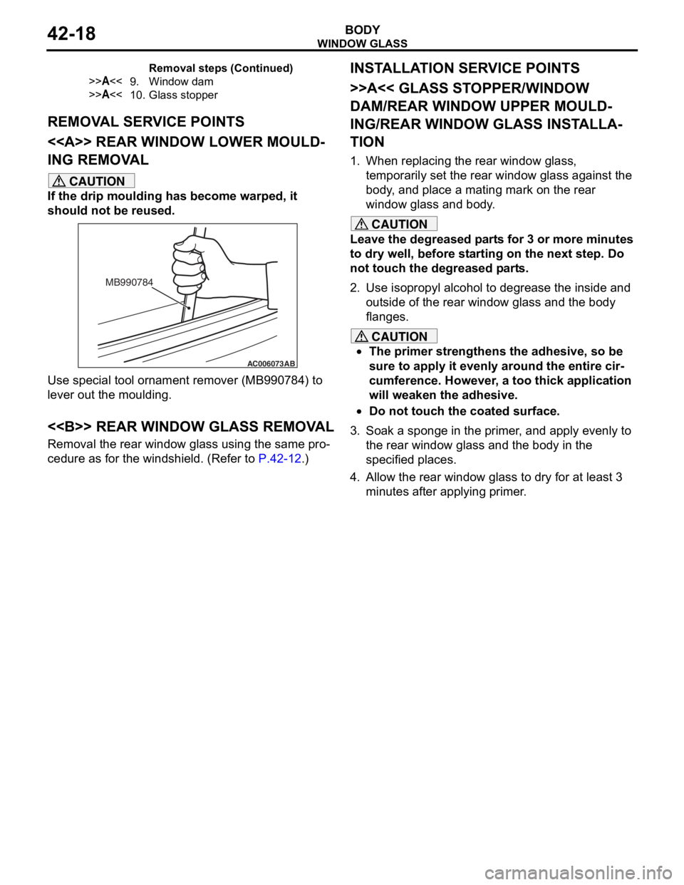
Page 294 of 800
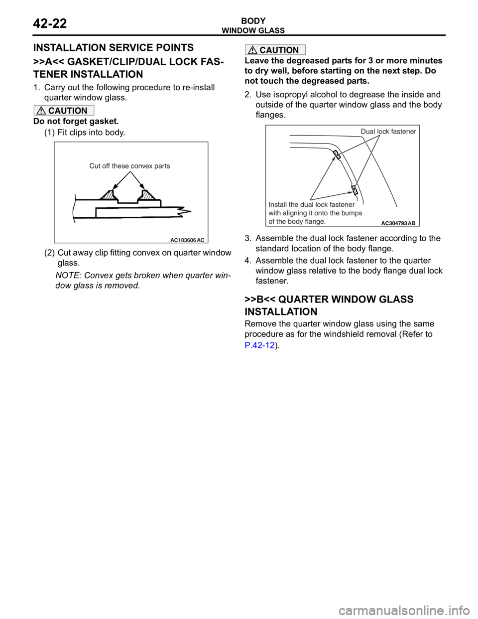
WINDOW GLASS
BODY42-22
INSTALLATION SERVICE POINTS
>>A<< GASKET/CLIP/DUAL LOCK FAS-
TENER INSTALLATION
1. Carry out the following procedure to re-install quarter window glass.
CAUTION
Do not forget gasket.
(1) Fit clips into body.
AC103606 AC
Cut off these convex parts
(2) Cut away clip fitting convex on quarter window
glass.
NOTE: Convex gets broken when quarter win-
dow glass is removed.
CAUTION
Leave the degreased parts for 3 or more minutes
to dry well, before starting on the next step. Do
not touch the degreased parts.
2. Use isopropyl alcohol to degrease the inside and
outside of the quarter window glass and the body
flanges.
AC304793AB
Dual lock fastener
Install the dual lock fastener
with aligning it onto the bumps
of the body flange.
3. Assemble the dual lock fastener according to the standard location of the body flange.
4. Assemble the dual lock fastener to the quarter window glass relative to the body flange dual lock
fastener.
>>B<< QUARTER WINDOW GLASS
INSTALLATION
Remove the quarter window glass using the same
procedure as for the windshield removal (Refer to
P.42-12).