ad blue MITSUBISHI LANCER 2006 User Guide
[x] Cancel search | Manufacturer: MITSUBISHI, Model Year: 2006, Model line: LANCER, Model: MITSUBISHI LANCER 2006Pages: 800, PDF Size: 45.03 MB
Page 422 of 800

ENGINE AND TRANSMISSION
CONFIGURATION DIAGRAMS80-12
ENGINE AND TRANSMISSION <4G1-MPI (LHD)> (CONTINUED)
AC301129AE
B-118B-101 B-102
B-113
B-114
B-115
B-116 B-117
Earth cable
Control wiring
harness
Connector colour
code
B : Black
BR : Brown
G : Green
GR : Grey
L : Blue
None : Milk white
O : Orange
R : Red
V : Violet
Y : Yellow
Connector
symbol
-101
thru
-118
B
*
B-101(2-BR)Emission solenoid valve (EGR system)
B-102(4-GR)Inlet manifold absolu te pressure sensor
B-103(6-B)Throttle body idle speed control servo
B-104(3-GR)Ignition coil 1
B-105(2-B)Emission solenoid va lve (Purge control
system)
B-107(3-B)Camshaft position sensor
B-108(3-GR)Output shaft speed sensor
B-109(3-B)Input shaft speed sensor
B-110(2-B)Back-up lamp switch
B-111(2-B)Water temperature sensor unit
Page 424 of 800
ENGINE AND TRANSMISSION
CONFIGURATION DIAGRAMS80-14
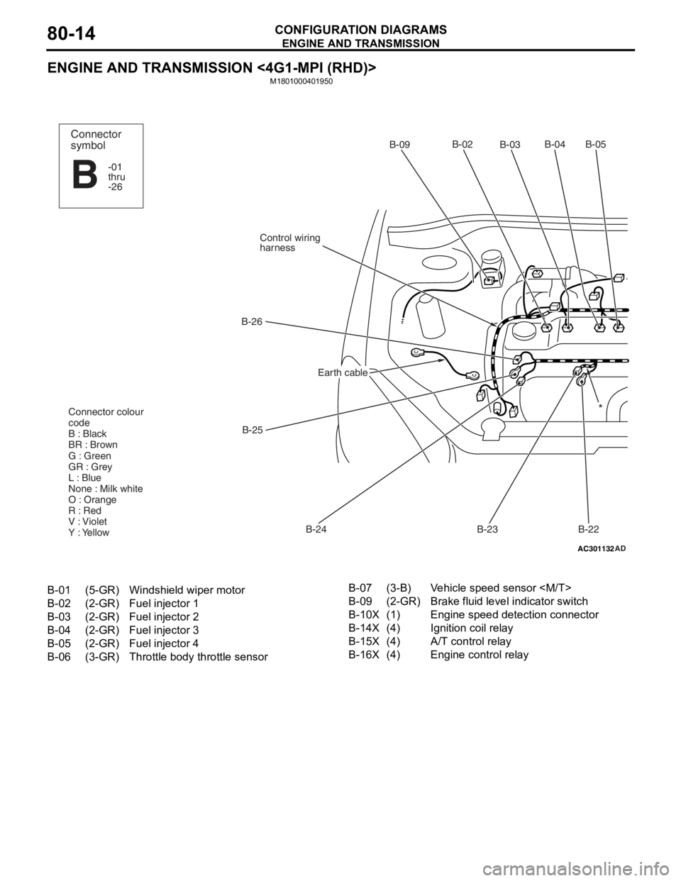
ENGINE AND TRANSMISSION <4G1-MPI (RHD)>
M1801000401950
AC301132AD
B-02
B-03B-04 B-05
B-22
B-23
B-24
B-25
B-26
Control wiring
harnessB-09
Connector colour
code
B : Black
BR : Brown
G : Green
GR : Grey
L : Blue
None : Milk white
O : Orange
R : Red
V : Violet
Y : Yellow*
Connector
symbol
-01
thru
-26
B
Earth cable
B-01(5-GR)Windshield wiper motor
B-02(2-GR)Fuel injector 1
B-03(2-GR)Fuel injector 2
B-04(2-GR)Fuel injector 3
B-05(2-GR)Fuel injector 4
B-06(3-GR)Throttle body throttle sensor
B-07(3-B)Vehicle speed sensor
B-09(2-GR)Brake fluid level indicator switch
B-10X(1)Engine speed detection connector
B-14X(4)Ignition coil relay
B-15X(4)A/T control relay
B-16X(4)Engine control relay
Page 426 of 800
ENGINE AND TRANSMISSION
CONFIGURATION DIAGRAMS80-16
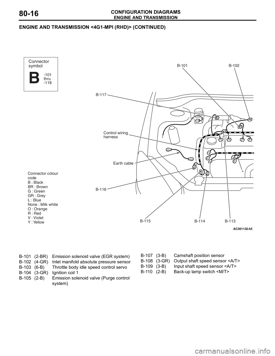
ENGINE AND TRANSMISSION <4G1-MPI (RHD)> (CONTINUED)
AC301132AE
B-117B-101 B-102
B-113
B-114
B-115
B-116
Earth cable
Control wiring
harness
Connector colour
code
B : Black
BR : Brown
G : Green
GR : Grey
L : Blue
None : Milk white
O : Orange
R : Red
V : Violet
Y : Yellow
Connector
symbol
-101
thru
-118
B
*
B-101(2-BR)Emission solenoid valve (EGR system)
B-102(4-GR)Inlet manifold absolu te pressure sensor
B-103(6-B)Throttle body idle speed control servo
B-104(3-GR)Ignition coil 1
B-105(2-B)Emission solenoid va lve (Purge control
system)
B-107(3-B)Camshaft position sensor
B-108(3-GR)Output shaft speed sensor
B-109(3-B)Input shaft speed sensor
B-110(2-B)Back-up lamp switch
Page 428 of 800
ENGINE AND TRANSMISSION
CONFIGURATION DIAGRAMS80-18
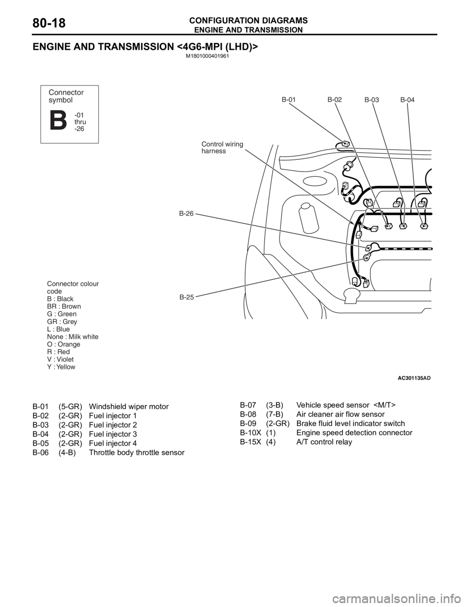
ENGINE AND TRANSMISSION <4G6-MPI (LHD)>
M1801000401961
AC301135AD
B-02
B-03B-04
B-25
B-26
Control wiring
harnessB-01
Connector colour
code
B : Black
BR : Brown
G : Green
GR : Grey
L : Blue
None : Milk white
O : Orange
R : Red
V : Violet
Y : YellowConnector
symbol
-01
thru
-26
B
B-01(5-GR)Windshield wiper motor
B-02(2-GR)Fuel injector 1
B-03(2-GR)Fuel injector 2
B-04(2-GR)Fuel injector 3
B-05(2-GR)Fuel injector 4
B-06(4-B)Throttle body throttle sensor
B-07(3-B)Vehicle speed sensor
B-08(7-B)Air cleaner air flow sensor
B-09(2-GR)Brake fluid level indicator switch
B-10X(1)Engine speed detection connector
B-15X(4)A/T control relay
Page 430 of 800
ENGINE AND TRANSMISSION
CONFIGURATION DIAGRAMS80-20
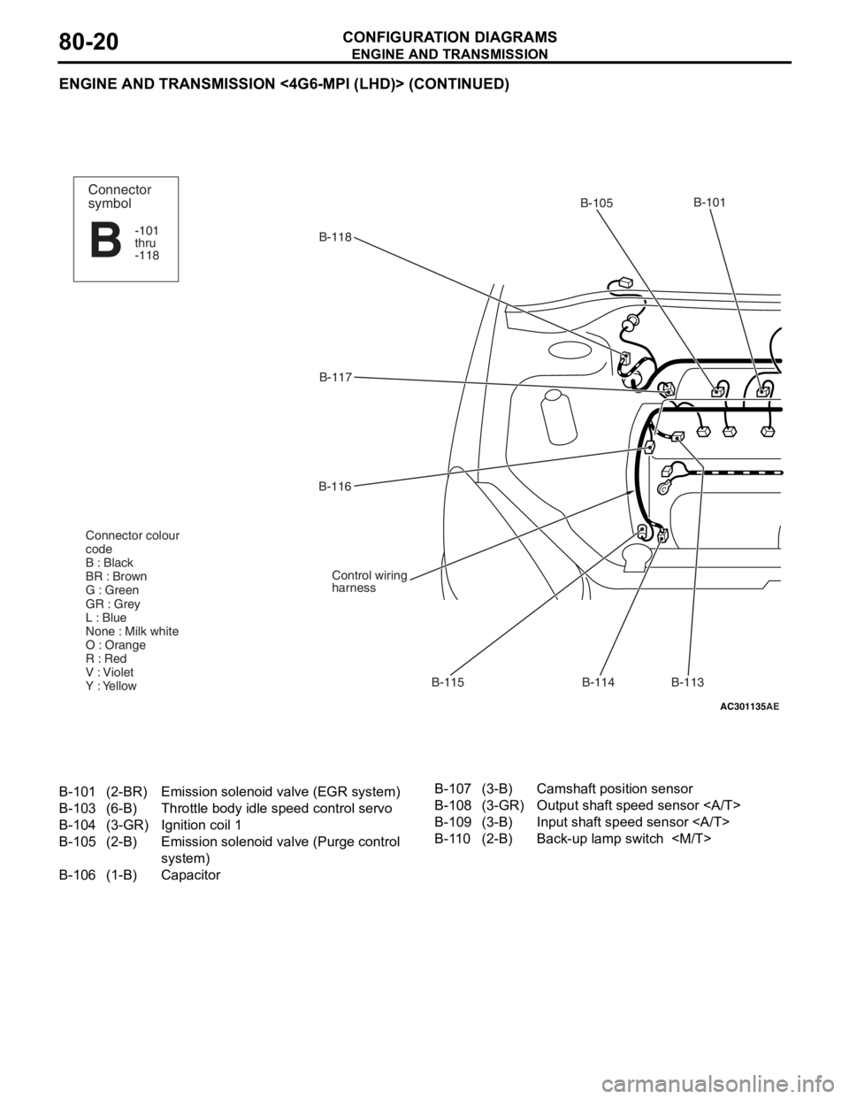
ENGINE AND TRANSMISSION <4G6-MPI (LHD)> (CONTINUED)
AC301135AE
B-118B-101
B-114
B-115
B-116
B-117
Control wiring
harness
Connector colour
code
B : Black
BR : Brown
G : Green
GR : Grey
L : Blue
None : Milk white
O : Orange
R : Red
V : Violet
Y : Yellow
B-113
B-105Connector
symbol
-101
thru
-118
B
B-101(2-BR)Emission solenoid
valve (EGR system)
B-103(6-B)Throttle body idle speed control servo
B-104(3-GR)Ignition coil 1
B-105(2-B)Emission solenoid va lve (Purge control
system)
B-106(1-B)Capacitor
B-107(3-B)Camshaft position sensor
B-108(3-GR)Output shaft speed sensor
B-109(3-B)Input shaft speed sensor
B-110(2-B)Back-up lamp switch
Page 432 of 800
ENGINE AND TRANSMISSION
CONFIGURATION DIAGRAMS80-22
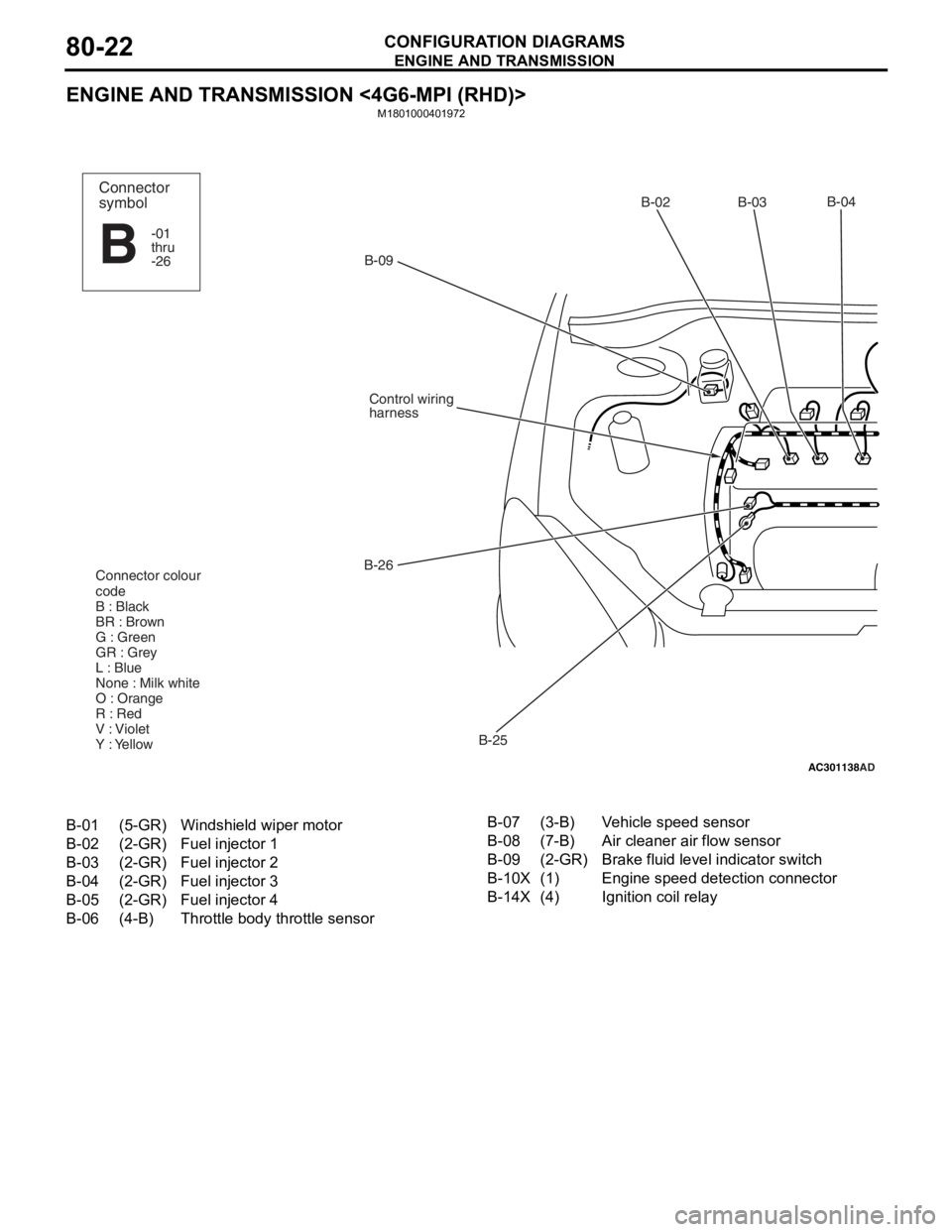
ENGINE AND TRANSMISSION <4G6-MPI (RHD)>
M1801000401972
AC301138
AD
B-02 B-03B-04
B-25
B-26
Control wiring
harness
B-09
Connector colour
code
B : Black
BR : Brown
G : Green
GR : Grey
L : Blue
None : Milk white
O : Orange
R : Red
V : Violet
Y : Yellow
Connector
symbol
-01
thru
-26
B
B-01(5-GR)Windshield wiper motor
B-02(2-GR)Fuel injector 1
B-03(2-GR)Fuel injector 2
B-04(2-GR)Fuel injector 3
B-05(2-GR)Fuel injector 4
B-06(4-B)Throttle body throttle sensor
B-07(3-B)Vehicle speed sensor
B-08(7-B)Air cleaner air flow sensor
B-09(2-GR)Brake fluid level indicator switch
B-10X(1)Engine speed detection connector
B-14X(4)Ignition coil relay
Page 434 of 800
ENGINE AND TRANSMISSION
CONFIGURATION DIAGRAMS80-24
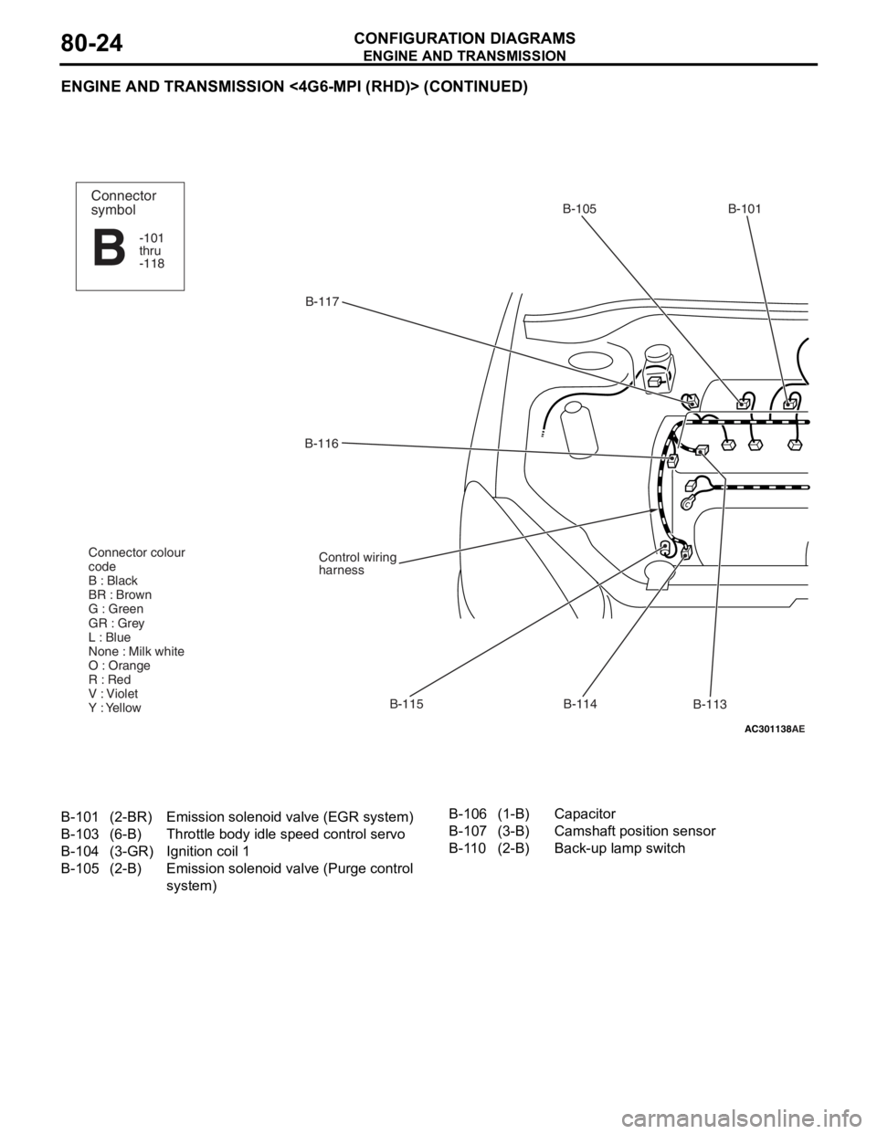
ENGINE AND TRANSMISSION <4G6-MPI (RHD)> (CONTINUED)
AC301138AE
B-117B-105 B-101
B-113
B-114
B-115
B-116
Control wiring
harness
Connector colour
code
B : Black
BR : Brown
G : Green
GR : Grey
L : Blue
None : Milk white
O : Orange
R : Red
V : Violet
Y : Yellow
Connector
symbol
-101
thru
-118
B
B-101(2-BR)Emission solenoid
valve (EGR system)
B-103(6-B)Throttle body idle speed control servo
B-104(3-GR)Ignition coil 1
B-105(2-B)Emission solenoid va lve (Purge control
system)
B-106(1-B)Capacitor
B-107(3-B)Camshaft position sensor
B-110(2-B)Back-up lamp switch
Page 436 of 800
DASH PANEL
CONFIGURATION DIAGRAMS80-26
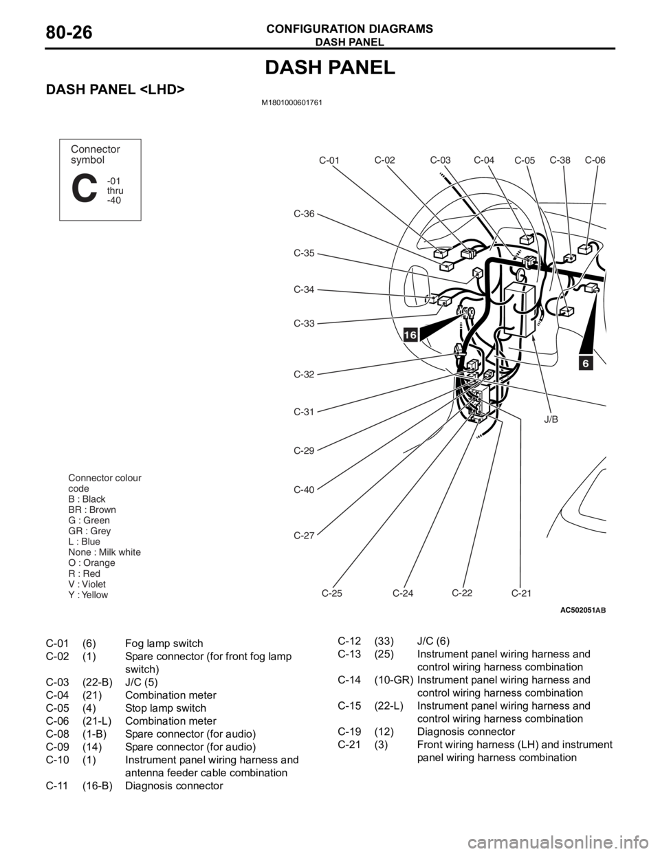
DASH PANEL
DASH PANEL
AC502051
16
C-38C-06
C-05
C-02
C-01
C-34
C-32 C-31
C-29
C-40
C-27
C-25 C-24C-22
C-21
Connector colour
code
B : Black
BR : Brown
G : Green
GR : Grey
L : Blue
None : Milk white
O : Orange
R : Red
V : Violet
Y : Yellow
Connector
symbol
-01
thru
-40
C
C-04
C-03
C-36
C-33
C-35
6
J/B
AB
C-01(6)Fog lamp switch
C-02(1)Spare connector (for front fog lamp
switch)
C-03(22-B)J/C (5)
C-04(21)Combination meter
C-05(4)Stop lamp switch
C-06(21-L)Combination meter
C-08(1-B)Spare connector (for audio)
C-09(14)Spare connector (for audio)
C-10(1)Instrument panel wiring harness and
antenna feeder cable combination
C-11(16-B)Diagnosis connector
C-12(33)J/C (6)
C-13(25)Instrument panel wiring harness and
control wiring harness combination
C-14(10-GR)Instrument panel wiring harness and
control wiring harness combination
C-15(22-L)Instrument panel wiring harness and
control wiring harness combination
C-19(12)Diagnosis connector
C-21(3)Front wiring harness (LH) and instrument
panel wiring har ness combination
Page 438 of 800
DASH PANEL
CONFIGURATION DIAGRAMS80-28
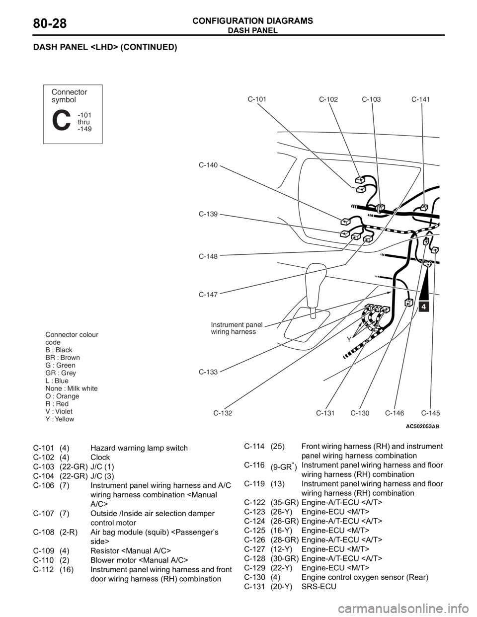
DASH PANEL
AC502053
C-140C-102
C-103
C-141
C-101
C-132
C-139
C-148
C-130
C-146C-145
Y
4
Connector
symbol
-101
thru
-149
C
Connector colour
code
B : Black
BR : Brown
G : Green
GR : Grey
L : Blue
None : Milk white
O : Orange
R : Red
V : Violet
Y : Yellow
Instrument panel
wiring harness
C-131
C-133
C-147
AB
C-101(4)Hazard warning lamp switch
C-102(4)Clock
C-103(22-GR)J/C (1)
C-104(22-GR)J/C (3)
C-106(7)Instrument panel wiring harness and A/C
wiring harness combination
C-107(7)Outside /Inside air selection damper
control motor
C-108(2-R)Air bag module (squib)
C-109(4)Resistor
C-110(2)Blower motor
C-112(16)Instrument panel wiring harness and front
door wiring harness (RH) combination
C-114(25)Front wiring harness (RH) and instrument
panel wiring har
ness combination
C-116(9-GR*)Instrument panel wiring harness and floor
wiring harness (RH) combination
C-119(13)Instrument panel wiring harness and floor
wiring harness (RH) combination
C-122(35-GR)Engine-A/T-ECU
C-123(26-Y)Engine-ECU
C-124(26-GR)Engine-A/T-ECU
C-125(16-Y)Engine-ECU
C-126(28-GR)Engine-A/T-ECU
C-127(12-Y)Engine-ECU
C-128(30-GR)Engine-A/T-ECU
C-129(22-Y)Engine-ECU
C-130(4)Engine control oxygen sensor (Rear)
C-131(20-Y)SRS-ECU
Page 441 of 800
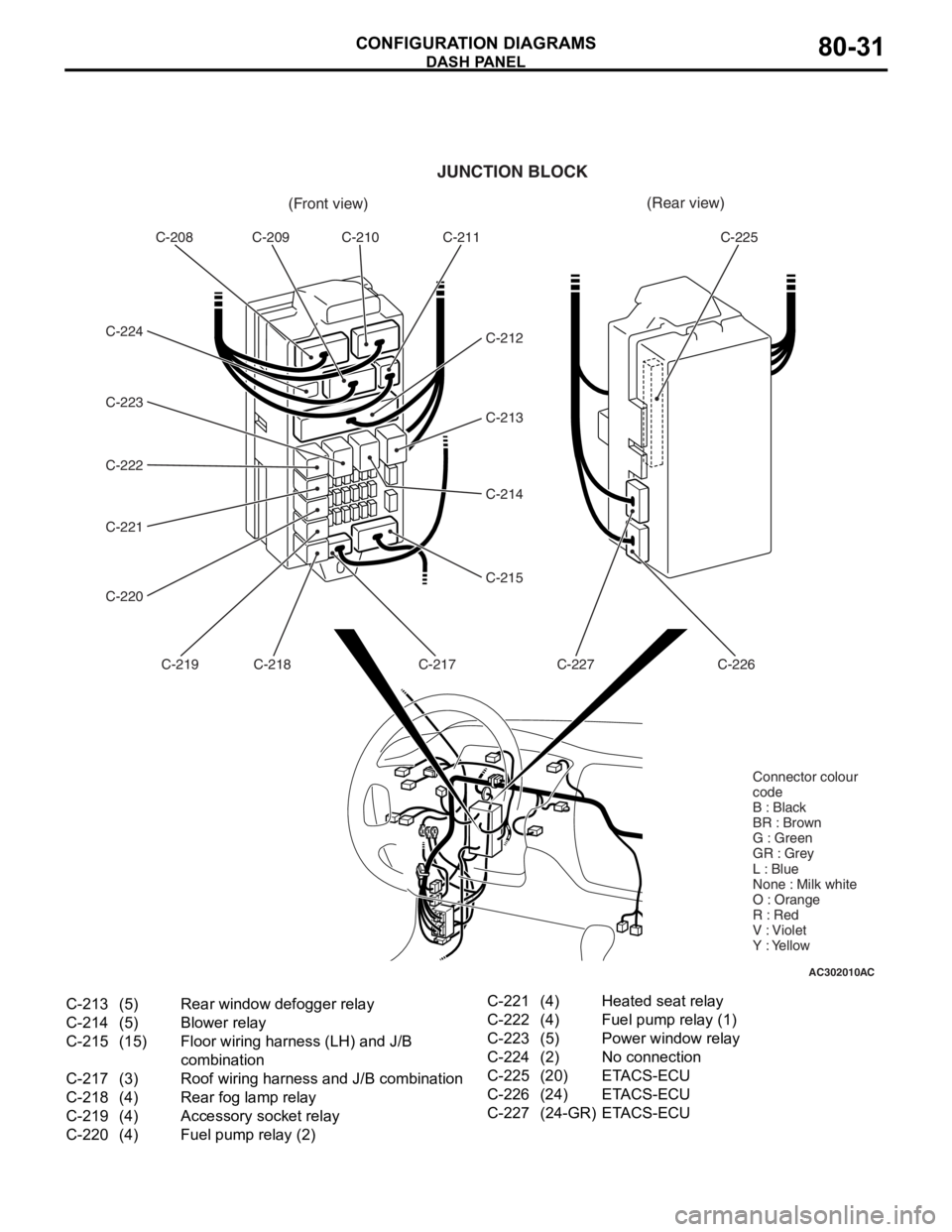
AC302010AC
(Front view)(Rear view)
C-208 C-209 C-210 C-211
C-212
C-213
C-214
C-215
C-217
C-218
C-219
C-220 C-221 C-222 C-223 C-224 C-225
C-226
C-227
JUNCTION BLOCK
Connector colour
code
B : Black
BR : Brown
G : Green
GR : Grey
L : Blue
None : Milk white
O : Orange
R : Red
V : Violet
Y : Yellow
C-213(5)Rear window defogger relay
C-214(5)Blower relay
C-215(15)Floor wiring harness (LH) and J/B
combination
C-217(3)Roof wiring harness and J/B combination
C-218(4)Rear fog lamp relay
C-219(4)Accessory socket relay
C-220(4)Fuel pump relay (2)
C-221(4)Heated seat relay
C-222(4)Fuel pump relay (1)
C-223(5)Power window relay
C-224(2)No connection
C-225(20)ETACS-ECU
C-226(24)ETACS-ECU
C-227(24-GR)ETACS-ECU
DASH P ANEL
CONF IGURA TION D I A G RA MS80-31