ad blue MITSUBISHI LANCER 2006 Owner's Manual
[x] Cancel search | Manufacturer: MITSUBISHI, Model Year: 2006, Model line: LANCER, Model: MITSUBISHI LANCER 2006Pages: 800, PDF Size: 45.03 MB
Page 442 of 800
DASH PANEL
CONFIGURATION DIAGRAMS80-32
DASH PANEL
M1801000601772
AC502055
C-10C-09 C-08
Control wiring
harness
C-37
C-16 C-17 C-18
C-11
C-19
Y
4
Connector
symbol
-01
thru
-39
C
Connector colour
code
B : Black
BR : Brown
G : Green
GR : Grey
L : Blue
None : Milk white
O : Orange
R : Red
V : Violet
Y : Yellow
Instrument panel
wiring harness
C-38
AB
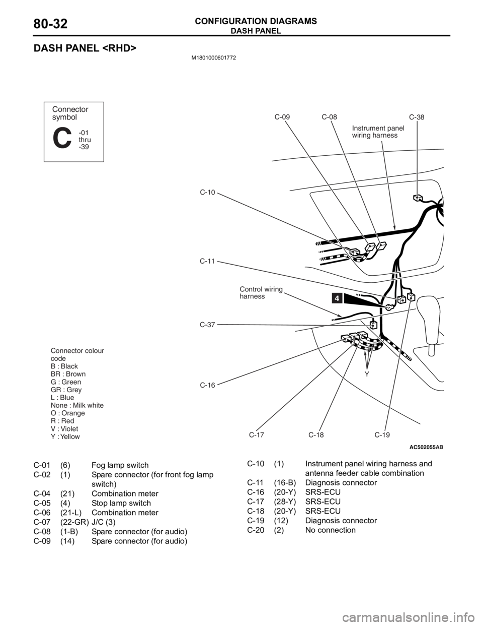
C-01(6)Fog lamp switch
C-02(1)Spare connector (for front fog lamp
switch)
C-04(21)Combination meter
C-05(4)Stop lamp switch
C-06(21-L)Combination meter
C-07(22-GR)J/C (3)
C-08(1-B)Spare connector (for audio)
C-09(14)Spare connector (for audio)
C-10(1)Instrument panel wiring harness and
antenna feeder cable combination
C-11(16-B)Diagnosis connector
C-16(20-Y)SRS-ECU
C-17(28-Y)SRS-ECU
C-18(20-Y)SRS-ECU
C-19(12)Diagnosis connector
C-20(2)No connection
Page 444 of 800
DASH PANEL
CONFIGURATION DIAGRAMS80-34
DASH PANEL
AC502057
Y
16
C-105
C-106
C-143
C-107
C-108
A/C wiring
harness
C-109
C-149
C-110
C-144
C-111
C-113
C-115
C-117
Instrument panel
wiring harness
Control wiring
harness
C-118 C-120
C-121C-128
C-129 C-126
C-127C-124
C-125
C-122
C-123
Connector colour
code
B : Black
BR : Brown
G : Green
GR : Grey
L : Blue
None : Milk white
O : Orange
R : Red
V : Violet
Y : Yellow
3
Connector
symbol
-101
thru
-149
C
Antenna
feeder
cable
AB
C-142
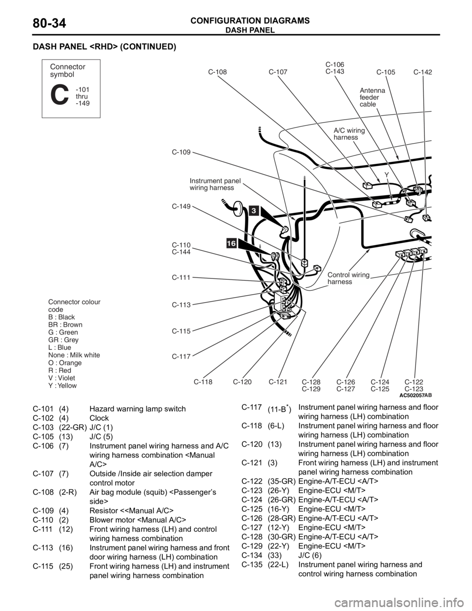
C-101(4)Hazard warning lamp switch
C-102(4)Clock
C-103(22-GR)J/C (1)
C-105(13)J/C (5)
C-106(7)Instrument panel wiring harness and A/C
wiring harness combination
C-107(7)Outside /Inside air selection damper
control motor
C-108(2-R)Air bag module (squib)
C-109(4)Resistor <
C-110(2)Blower motor
C-111(12)Front wiring harness (LH) and control
wiring harness combination
C-113(16)Instrument panel wiring harness and front
door wiring harness (LH) combination
C-115(25)Front wiring harness (LH) and instrument
panel wiring harn
ess combination
C-117(11-B*)Instrument panel wiring harness and floor
wiring harness (LH) combination
C-118(6-L)Instrument panel wiring harness and floor
wiring harness (LH) combination
C-120(13)Instrument panel wiring harness and floor
wiring harness (LH) combination
C-121(3)Front wiring harness (LH) and instrument
panel wiring harness combination
C-122(35-GR)Engine-A/T-ECU
C-123(26-Y)Engine-ECU
C-124(26-GR)Engine-A/T-ECU
C-125(16-Y)Engine-ECU
C-126(28-GR)Engine-A/T-ECU
C-127(12-Y)Engine-ECU
C-128(30-GR)Engine-A/T-ECU
C-129(22-Y)Engine-ECU
C-134(33)J/C (6)
C-135(22-L)Instrument panel wiring harness and
control wiring harness combination
Page 447 of 800
AC302011AC
(Front view)(Rear view)
C-208 C-209 C-210 C-211
C-212
C-213
C-214
C-216
C-217
C-218
C-219
C-220 C-221 C-222 C-223 C-224 C-225
C-226
C-227
JUNCTION BLOCK
Connector colour
code
B : Black
BR : Brown
G : Green
GR : Grey
L : Blue
None : Milk white
O : Orange
R : Red
V : Violet
Y : Yellow
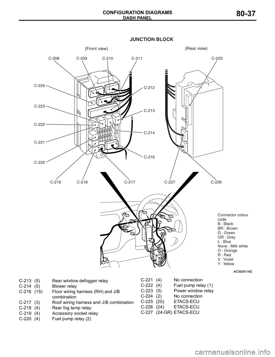
C-213(5)Rear window defogger relay
C-214(5)Blower relay
C-216(15)Floor wiring harness (RH) and J/B
combination
C-217(3)Roof wiring harness and J/B combination
C-218(4)Rear fog lamp relay
C-219(4)Accessory socket relay
C-220(4)Fuel pump relay (2)
C-221(4)No connection
C-222(4)Fuel pump relay (1)
C-223(5)Power window relay
C-224(2)No connection
C-225(20)ETACS-ECU
C-226(24)ETACS-ECU
C-227(24-GR)ETACS-ECU
DASH P ANEL
CONF IGURA TION D I A G RA MS80-37
Page 448 of 800
FLOOR AND ROOF
CONFIGURATION DIAGRAMS80-38
FLOOR AND ROOF
FLOOR AND ROOF
AC502059
D-06
D-07
D-05
D-04
D-03
D-02
D-01
D-35
D-39D-33
D-38D-32
D-34
D-31
D-30
D-29
D-25
D-28 D-27 D-24
D-23Y
Y Floor wiring
harness (LH)
Floor wiring
harness (RH)
Instrument panel
wiring harness
Connector
symbol
D
D-26
Roof wiring
harness
Connector colour
code
B : Black
BR : Brown
G : Green
GR : Grey
L : Blue
None : Milk white
O : Orange
R : Red
V : Violet
Y : Yellow
Antenna
feeder cable
AB
Y
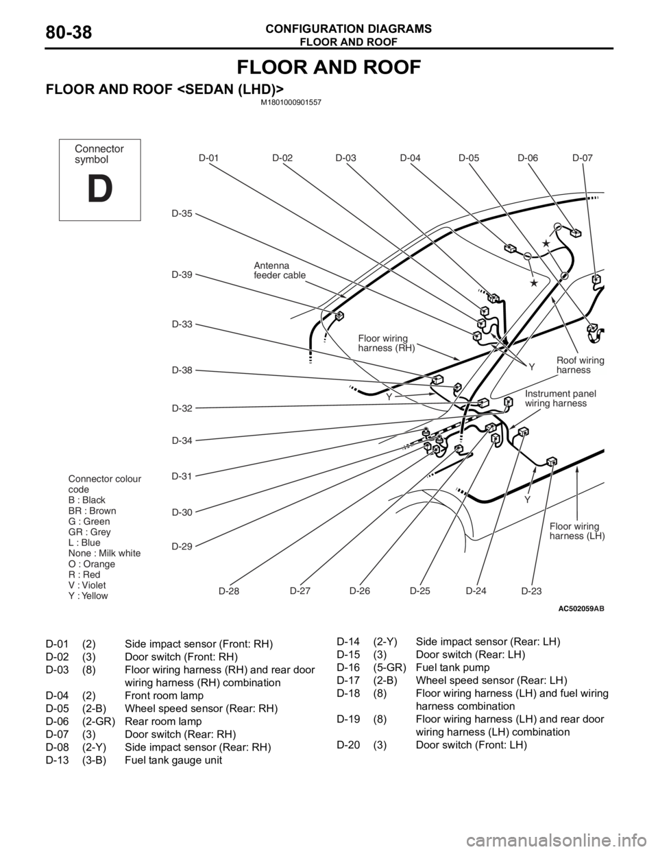
D-01(2)Side impact sensor (Front: RH)
D-02(3)Door switch (Front: RH)
D-03(8)Floor wiring harness (RH) and rear door
wiring harness (RH) combination
D-04(2)Front room lamp
D-05(2-B)Wheel speed sensor (Rear: RH)
D-06(2-GR)Rear room lamp
D-07(3)Door switch (Rear: RH)
D-08(2-Y)Side impact sensor (Rear: RH)
D-13(3-B)Fuel tank gauge unit
D-14(2-Y)Side impact sensor (Rear: LH)
D-15(3)Door switch (Rear: LH)
D-16(5-GR)Fuel tank pump
D-17(2-B)Wheel speed sensor (Rear: LH)
D-18(8)Floor wiring harness (LH) and fuel wiring
harness combination
D-19(8)Floor wiring harness (LH) and rear door
wiring harness (LH) combination
D-20(3)Door switch (Front: LH)
Page 450 of 800
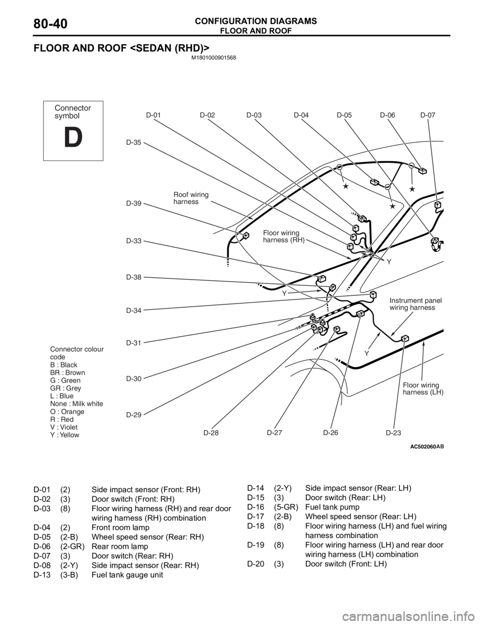
FLOOR AND ROOF
CONFIGURATION DIAGRAMS80-40
FLOOR AND ROOF
M1801000901568
AC502060
D-06
D-07
D-05
D-04
D-03
D-02
D-01
D-35
D-34D-33
D-39
D-38
D-31 D-30
D-29 D-28D-27
D-23Y
Y
YFloor wiring
harness (LH)
Floor wiring
harness (RH)
Instrument panel
wiring harness
Connector
symbol
D
D-26
Roof wiring
harness
Connector colour
code
B : Black
BR : Brown
G : Green
GR : Grey
L : Blue
None : Milk white
O : Orange
R : Red
V : Violet
Y : Yellow
AB
D-01(2)Side impact sensor (Front: RH)
D-02(3)Door switch (Front: RH)
D-03(8)Floor wiring harness (RH) and rear door
wiring harness (RH) combination
D-04(2)Front room lamp
D-05(2-B)Wheel speed sensor (Rear: RH)
D-06(2-GR)Rear room lamp
D-07(3)Door switch (Rear: RH)
D-08(2-Y)Side impact sensor (Rear: RH)
D-13(3-B)Fuel tank gauge unit
D-14(2-Y)Side impact sensor (Rear: LH)
D-15(3)Door switch (Rear: LH)
D-16(5-GR)Fuel tank pump
D-17(2-B)Wheel speed sensor (Rear: LH)
D-18(8)Floor wiring harness (LH) and fuel wiring
harness combination
D-19(8)Floor wiring harness (LH) and rear door
wiring harness (LH) combination
D-20(3)Door switch (Front: LH)
Page 452 of 800
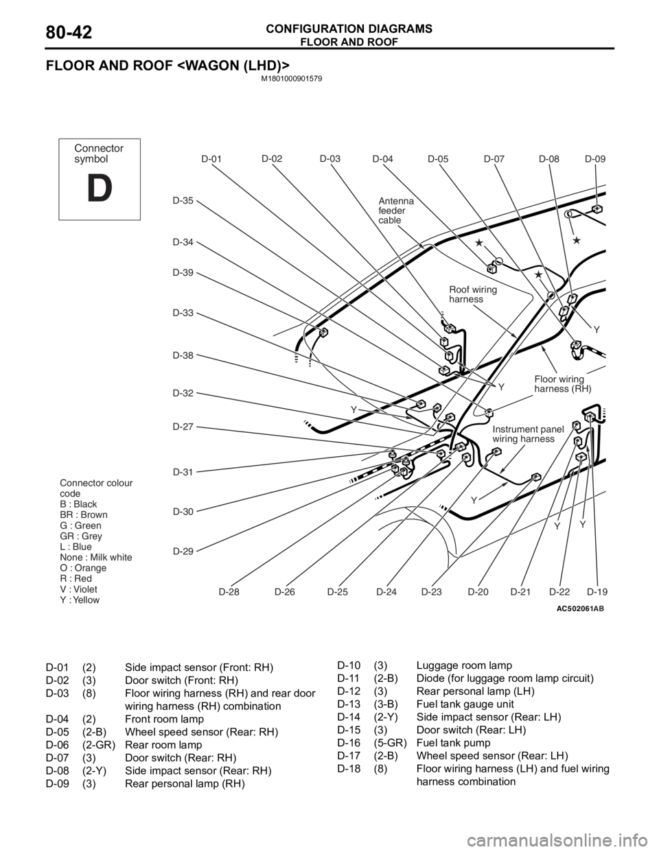
FLOOR AND ROOF
CONFIGURATION DIAGRAMS80-42
FLOOR AND ROOF
M1801000901579
AC502061
D-07D-08
D-05
D-04
D-03
D-02
D-01
D-35
D-34
D-33
D-38
D-32
D-39
D-31
D-30
D-29
D-28 D-24 D-19
Y
Y Y
Connector
symbol
D
D-20
Roof wiring
harness
Connector colour
code
B : Black
BR : Brown
G : Green
GR : Grey
L : Blue
None : Milk white
O : Orange
R : Red
V : Violet
Y : Yellow
D-09
D-22D-21D-23D-25D-26
D-27
Y
YInstrument panel
wiring harness
Floor wiring
harness (RH)
Y
Antenna
feeder
cable
AB
D-01(2)Side impact sensor (Front: RH)
D-02(3)Door switch (Front: RH)
D-03(8)Floor wiring harness (RH) and rear door
wiring harness (RH) combination
D-04(2)Front room lamp
D-05(2-B)Wheel speed sensor (Rear: RH)
D-06(2-GR)Rear room lamp
D-07(3)Door switch (Rear: RH)
D-08(2-Y)Side impact sensor (Rear: RH)
D-09(3)Rear personal lamp (RH)
D-10(3)Luggage room lamp
D-11(2-B)Diode (for luggage room lamp circuit)
D-12(3)Rear personal lamp (LH)
D-13(3-B)Fuel tank gauge unit
D-14(2-Y)Side impact sensor (Rear: LH)
D-15(3)Door switch (Rear: LH)
D-16(5-GR)Fuel tank pump
D-17(2-B)Wheel speed sensor (Rear: LH)
D-18(8)Floor wiring harness (LH) and fuel wiring
harness combination
Page 454 of 800
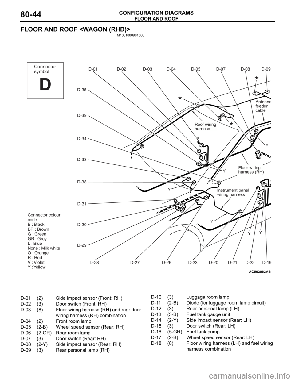
FLOOR AND ROOF
CONFIGURATION DIAGRAMS80-44
FLOOR AND ROOF
M1801000901580
AC502062
D-07
D-08
D-05
D-04
D-03
D-02
D-01
D-35
D-34
D-33
D-39
D-38
D-31
D-30
D-29 D-28 D-19
Y
Y Y
Connector
symbol
D
D-20
Roof wiring
harness
Connector colour
code
B : Black
BR : Brown
G : Green
GR : Grey
L : Blue
None : Milk white
O : Orange
R : Red
V : Violet
Y : Yellow
D-09
D-22D-21D-23D-26D-27 Y
Y
Instrument panel
wiring harness
Floor wiring
harness (RH)
Y
Antenna
feeder
cable
AB
D-01(2)Side impact sensor (Front: RH)
D-02(3)Door switch (Front: RH)
D-03(8)Floor wiring harness (RH) and rear door
wiring harness (RH) combination
D-04(2)Front room lamp
D-05(2-B)Wheel speed sensor (Rear: RH)
D-06(2-GR)Rear room lamp
D-07(3)Door switch (Rear: RH)
D-08(2-Y)Side impact sensor (Rear: RH)
D-09(3)Rear personal lamp (RH)
D-10(3)Luggage room lamp
D-11(2-B)Diode (for luggage room lamp circuit)
D-12(3)Rear personal lamp (LH)
D-13(3-B)Fuel tank gauge unit
D-14(2-Y)Side impact sensor (Rear: LH)
D-15(3)Door switch (Rear: LH)
D-16(5-GR)Fuel tank pump
D-17(2-B)Wheel speed sensor (Rear: LH)
D-18(8)Floor wiring harness (LH) and fuel wiring
harness combination
Page 457 of 800
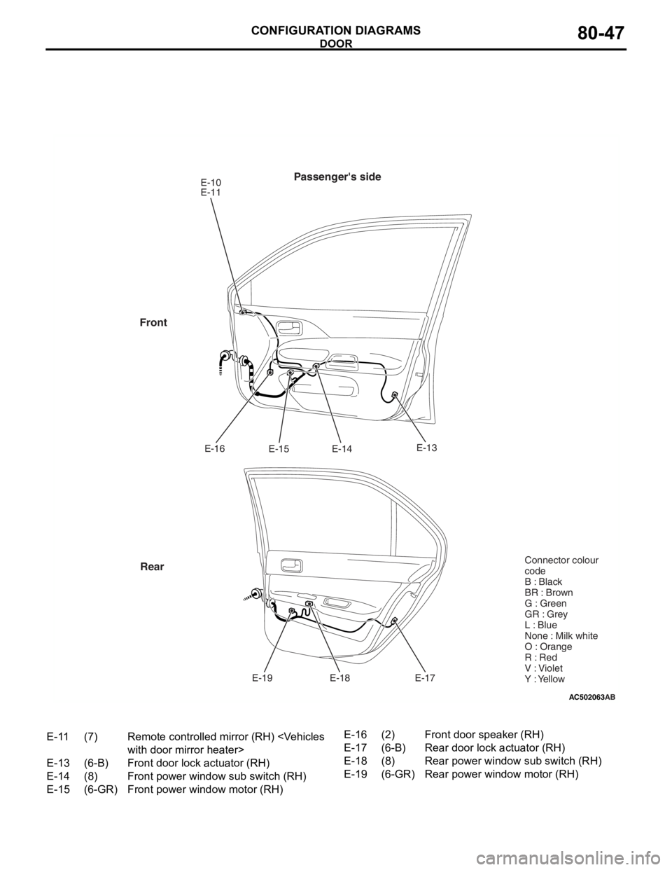
AC502063
Passenger's sideE-10
E-11E-14
E-15
E-16
E-17
E-18
E-19
Front
Rear
AB
E-13 Connector colour
code
B : Black
BR : Brown
G : Green
GR : Grey
L : Blue
None : Milk white
O : Orange
R : Red
V : Violet
Y : Yellow
E-11(7)Remote controlled mirror (RH)
E-13(6-B)Front door lock actuator (RH)
E-14(8)Front power window sub switch (RH)
E-15(6-GR)Front power window motor (RH)
E-16(2)Front door speaker (RH)
E-17(6-B)Rear door lock actuator (RH)
E-18(8)Rear power window sub switch (RH)
E-19(6-GR)Rear power window motor (RH)
DOOR
CONF IGURA TION D I A G RA MS80-47
Page 459 of 800
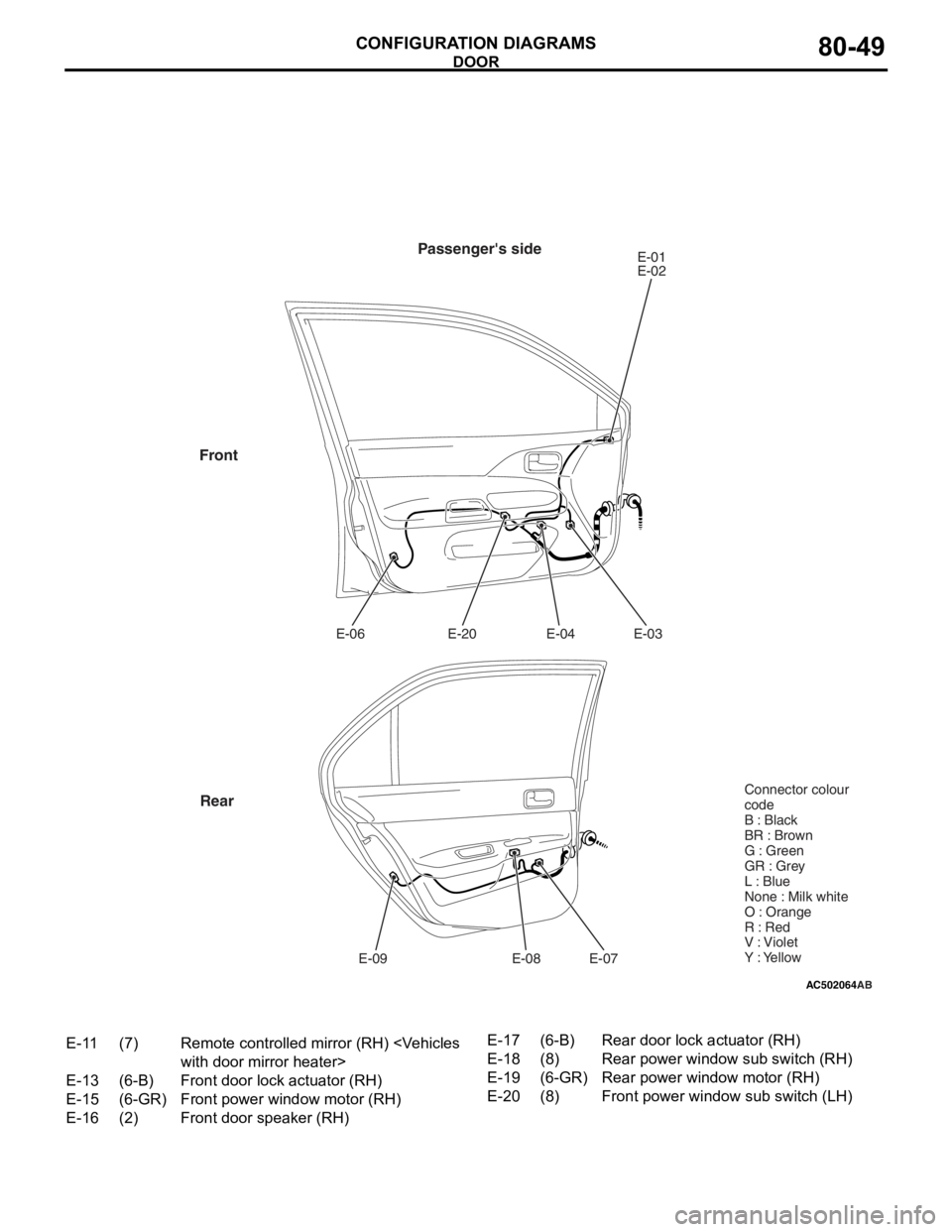
AC502064
Passenger's sideE-01
E-02
E-03
E-04
E-20
E-06
E-07
E-08
E-09
Front
Rear
AB
Connector colour
code
B : Black
BR : Brown
G : Green
GR : Grey
L : Blue
None : Milk white
O : Orange
R : Red
V : Violet
Y : Yellow
E-11(7)Remote controlled mirror (RH)
E-13(6-B)Front door lock actuator (RH)
E-15(6-GR)Front power window motor (RH)
E-16(2)Front door speaker (RH)
E-17(6-B)Rear door lock actuator (RH)
E-18(8)Rear power window sub switch (RH)
E-19(6-GR)Rear power window motor (RH)
E-20(8)Front power window sub switch (LH)
DOOR
CON F IGURA TION D I A G RA MS80-49
Page 460 of 800
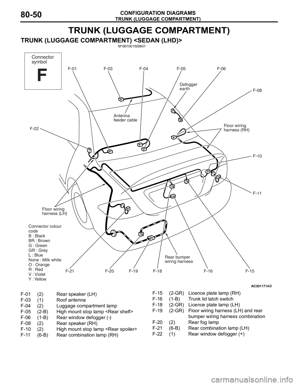
TRUNK (LUGGAGE COMPARTMENT)
CONFIGURATION DIAGRAMS80-50
TRUNK (LUGGAGE COMPARTMENT)
TRUNK (LUGGAGE COMPARTMENT)
AC301171AD
F-01 F-04 F-05 F-06
F-08
F-10
F-11
F-18 F-16
F-19
Floor wiring
harness (LH)
F-22
Defogger
earth
Floor wiring
harness (RH)F-03
F-15F-21
Rear bumper
wiring harness
Antenna
feeder cable
Connector colour
code
B : Black
BR : Brown
G : Green
GR : Grey
L : Blue
None : Milk white
O : Orange
R : Red
V : Violet
Y : Yellow
F-20
Connector
symbol
F
F-01(2)Rear speaker (LH)
F-03(1)Roof antenna
F-04(2)Luggage compartment lamp
F-05(2-B)High mount stop lamp
F-06(1-B)Rear window defogger (−)
F-08(2)Rear speaker (RH)
F-10(2)High mount stop lamp
F-11(6-B)Rear combination lamp (RH)
F-15(2-GR)Licence plate lamp (RH)
F-16(1-B)Trunk lid latch switch
F-18(2-GR)Licence plate lamp (LH)
F-19(2-GR)Floor wiring harness (LH) and rear
bumper wiring harness combination
F-20(2)Rear fog lamp
F-21(6-B)Rear combination lamp (LH)
F-22(1)Rear window defogger (+)