battery MITSUBISHI LANCER 2006 User Guide
[x] Cancel search | Manufacturer: MITSUBISHI, Model Year: 2006, Model line: LANCER, Model: MITSUBISHI LANCER 2006Pages: 800, PDF Size: 45.03 MB
Page 70 of 800

CHARGING SYSTEM
ENGINE ELECTRICAL16-8
If the voltage is not within the standard value,
there is a malfunction of the voltage regulator or of
the alternator.
14.After the test, lower the engine speed to the idle speed.
15.Turn the ignition switch to the "LOCK" (OFF) position.
16.Remove the tachometer or the M.U.T.-II/III.
17.Disconnect the negative battery cable.
18.Disconnect the ammeter and voltmeter.
19.Connect the alternator output wire to the alternator "B" terminal.
20.Remove the special tool, and return the connector
to the original condition.
21.Connect the negative battery cable.
Voltage Regulation Table
Standard value:
Inspection terminalVoltage regulator ambient
temperature
°C
Voltage V
Terminal "S"−2014.2 − 15.4
2013.9 − 14.9
6013.4 − 14.6
8013.1 − 14.5
Page 75 of 800
CHARGING SYSTEM
ENGINE ELECTRICAL16-13
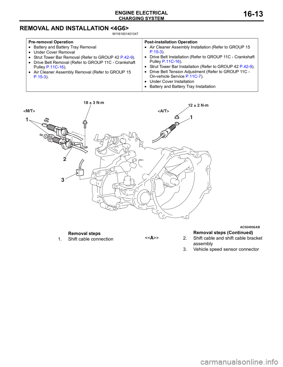
REMOVAL AND INSTALLATION <4G6>
M1161001401347
Pre-removal Operation
•Battery and Battery Tray Removal
•Under Cover Removal
•Strut Tower Bar Removal (Refer to GROUP 42 P.42-9).
•Drive Belt Removal (Refer to GROUP 11C - Crankshaft
Pulley P.11C-16).
•Air Cleaner Assembly Remo val (Refer to GROUP 15 P.15-3).
Post-installation Operation
•Air Cleaner Assembly Installation (Refer to GROUP 15 P.15-3).
•Drive Belt Installation (Refer to GROUP 11C - Crankshaft
Pulley P.11C-16).
•Strut Tower Bar Installation (Refer to GROUP 42 P.42-9).
•Drive Belt Tension Adjustment (Refer to GROUP 11C -
On-vehicle Service
P.11C-7).
•Under Cover Installation
•Battery and Battery Tray Installation
AC504936
1 1
2
3
18 ± 3 N·m 12 ± 2 N·m
AB
Removal steps
1.Shift cable connection<>2.Shift cable and shift cable bracket
assembly
3.Vehicle speed sensor connector
Removal steps (Continued)
Page 76 of 800
AC303827
65
84
9
7
22 ± 4 N·m
23 ± 3 N·m
8.8 ± 1.0 N·m 44 ± 10 N·m
AB
13 ± 3 N·m
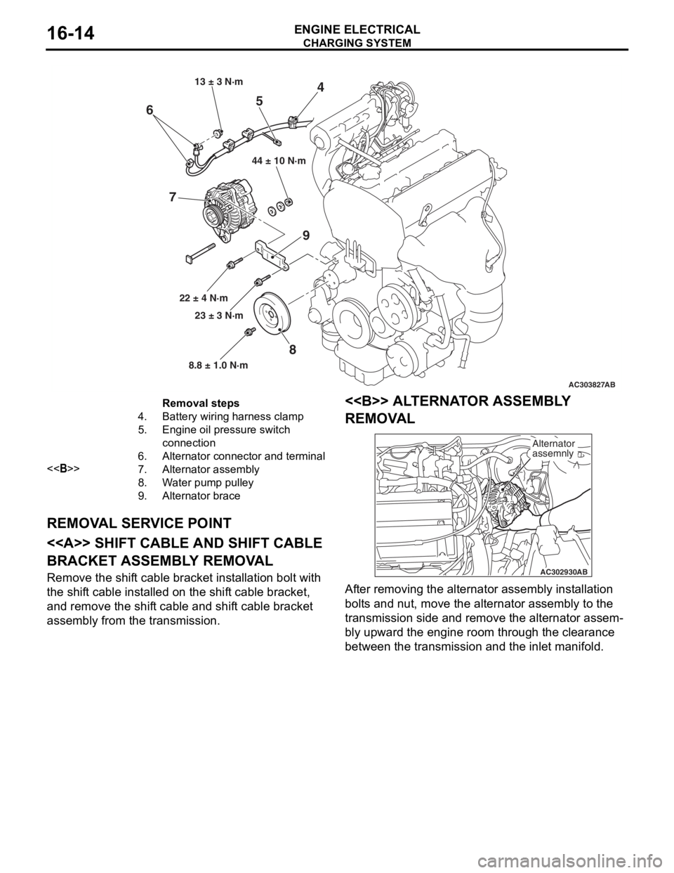
Removal steps
4.Battery wiring harness clamp
5.Engine oil pressure switch
connection
6.Alternator connector and terminal
<>7.Alternator assembly
8.Water pump pulley
9.Alternator brace
CHARGING SYSTEM
ENGINE ELECTRICAL16-14
REMOV
A L SER V ICE POINT
<> SHIFT CABLE AND SHIFT CABLE
BRACKET ASSEMBL
Y REMOV A L
Remove the shift cable bracket inst allation bolt with
the shif
t ca ble inst alled o n the shif t cable bracket,
and remove
the shif t cable and shif t cable bracket
assembly fro
m the transmission.
<> ALTERNA T O R ASSEMBL Y
REMOV
A L
AC302930 AB
Alternator
assemnly
Af
ter re moving the alternato r assembly inst allation
bolt
s a nd nu t, move the alte rnator a sse mbly to the
transmission side an
d remove the alternato r assem
-
bly upward the engine roo m thr ough th e clearan ce
between t
he tran smission and the inlet ma nifold.
Page 81 of 800
STARTING SYSTEM
ENGINE ELECTRICAL16-19
STARTING SYSTEM
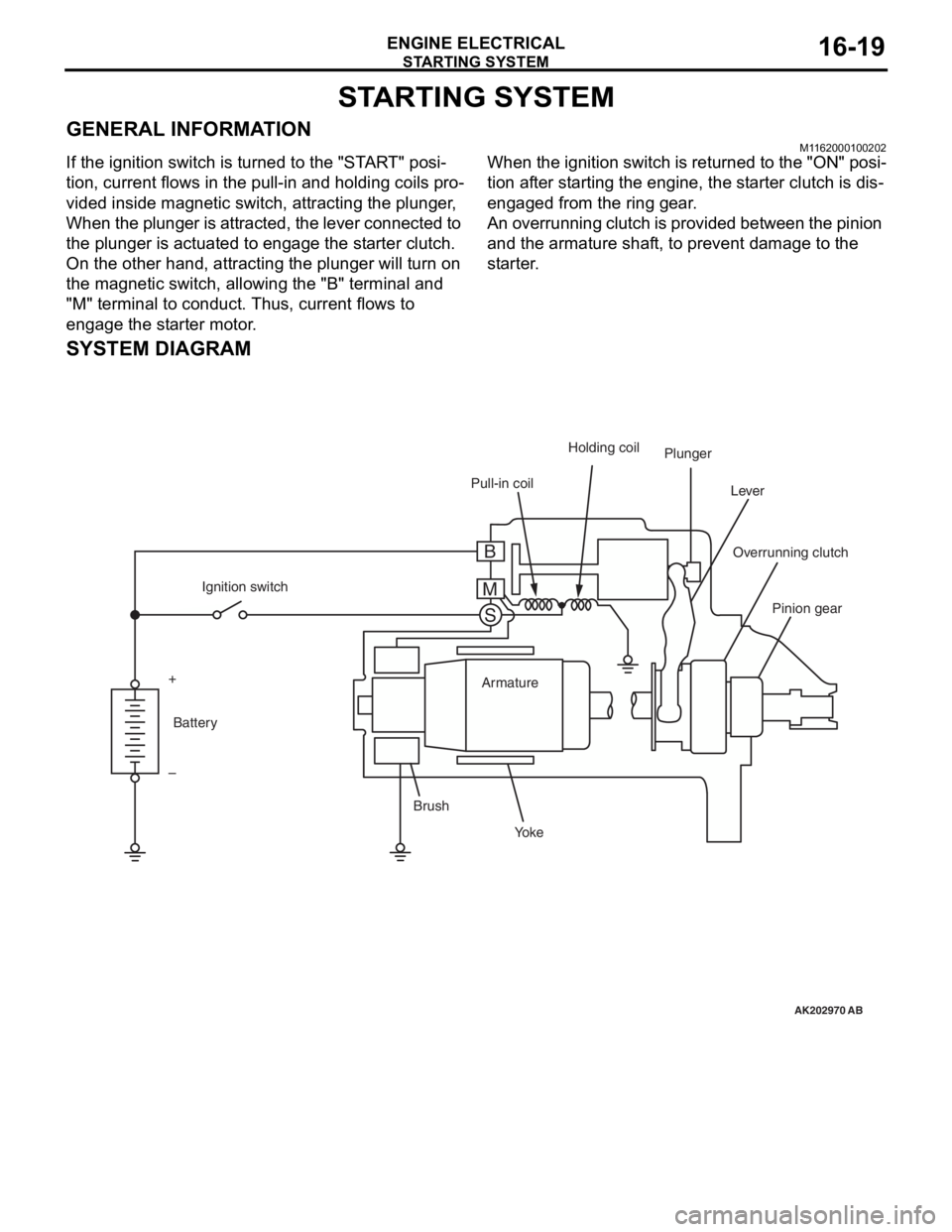
GENERAL INFORMATIONM1162000100202
If the ignition switch is turned to the "START" posi-
tion, current flows in the pull-in and holding coils pro-
vided inside magnetic switch, attracting the plunger,
When the plunger is attracted, the lever connected to
the plunger is actuated to engage the starter clutch.
On the other hand, attracting the plunger will turn on
the magnetic switch, allowing the "B" terminal and
"M" terminal to conduct. Thus, current flows to
engage the starter motor.
When the ignition switch is returned to the "ON" posi-
tion after starting the engine, the starter clutch is dis-
engaged from the ring gear.
An overrunning clutch is provided between the pinion
and the armature shaft, to prevent damage to the
starter.
SYSTEM DIAGRAM
AK202970
Pull-in coilHolding coil
Plunger
Lever
Pinion gear
Overrunning clutch
Yo k e
Brush Armature
Ignition switch
Battery
+
–
AB
B
M S
Page 83 of 800
STARTING SYSTEM
ENGINE ELECTRICAL16-21
STARTER MOTOR ASSEMBLY
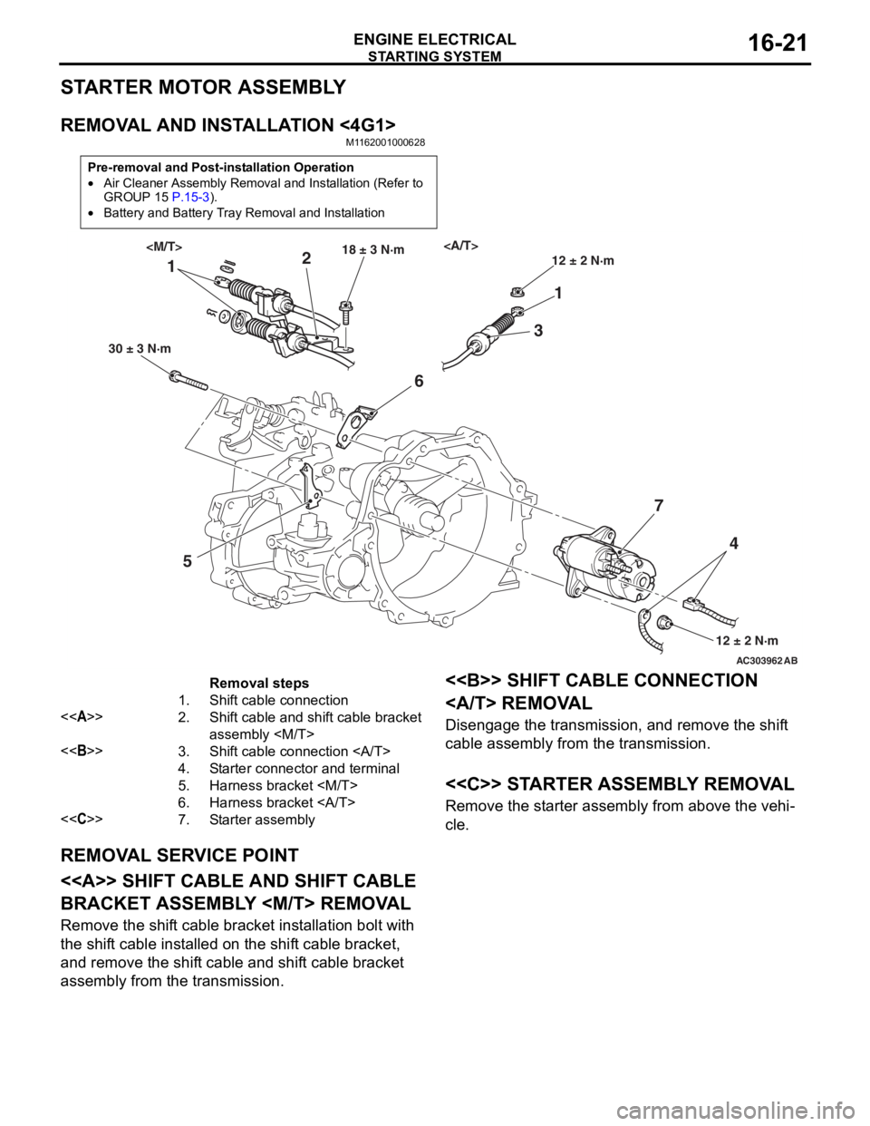
REMOVAL AND INSTALLATION <4G1>
M1162001000628
Pre-removal and Post-installation Operation
•Air Cleaner Assembly Removal and Installation (Refer to
GROUP 15 P.15-3).
•Battery and Battery Tray Removal and Installation
AC303962AB
11
2
3
5 6
74
30 ± 3 N·m 18 ± 3 N·m
12 ± 2 N·m
12 ± 2 N·m
Removal steps
1.Shift cable connection
<>2.Shift cable and shift cable bracket
assembly
<>3.Shift cable connection
4.Starter connector and terminal
5.Harness bracket
6.Harness bracket
<
REMOVA L SER V ICE POINT
<> SHIFT CABLE AND SHIFT CABLE
BRACKET ASSEMBL
Y
Remove the shift cable bracket inst allation bolt with
the shif
t ca ble inst alled o n the shif t cable bracket,
and remove
the shif t cable and shif t cable bracket
assembly fro
m the transmission.
<> SHIFT CABLE CONNECTION
REMOVA L
Disengage th e transmission, a nd remove the shif t
cable assembly from the tra
n smission .
<
Remove the st arter assembly from above the veh i-
cle.
Page 85 of 800
STARTING SYSTEM
ENGINE ELECTRICAL16-23
STARTER MOTOR ASSEMBLY INSPECTION
M1162001100205
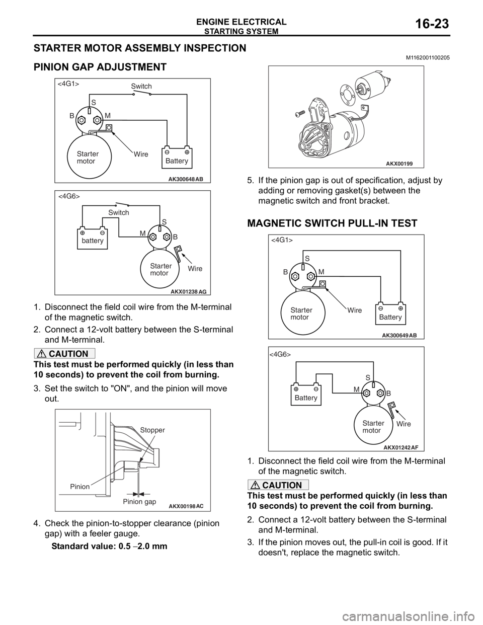
PINION GAP ADJUSTMENT
AK300648AB
<4G1>
Switch
S M
Wire Battery
Starter
motor
B
AKX01238
<4G6>
B
M S
battery Switch
Starter
motorWire
AG
1.
Disco nnect the field coil wire f r om th e M-te rmin al
of the magnet ic switch.
2.Conn ect a 12-volt b a ttery between the S-termina l
an d M-t e rminal.
CAUTION
This test must be performed quickly (in less than
10 seconds) to prevent the coil from burning.
3. Set the switch to "ON", and the pinion will move out.
AKX00198
Stopper
Pinion gap
Pinion
AC
4. Check the pinion-to-stopper clearance (pinion
gap) with a feeler gauge.
Standard value: 0.5 − 2.0 mm
AKX00199
5. If the pinion gap is out of specification, adjust by adding or removing gasket(s) between the
magnetic switch and front bracket.
MAGNETIC SWITCH PULL-IN TEST
AK300649AB
<4G1>
SM
Wire Battery
Starter
motor
B
AKX01242
<4G6>
SB
M
Battery
Starter
motorWire
AF
1. Disconnect the field coil wire from the M-terminal
of the magnetic switch.
CAUTION
This test must be performed quickly (in less than
10 seconds) to prevent the coil from burning.
2. Connect a 12-volt battery between the S-terminal and M-terminal.
3. If the pinion moves out, the pull-in coil is good. If it doesn't, replace the magnetic switch.
Page 86 of 800
STARTING SYSTEM
ENGINE ELECTRICAL16-24
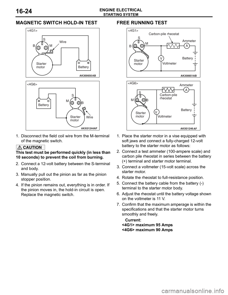
MAGNETIC SWITCH HOLD-IN TEST
AK300650AB
<4G1>S
B MWire
Battery
Starter
motor
AKX01244
<4G6>
SB
M
Battery
Starter
motorWire
AF
1.
Disco nnect the field coil wire f r om th e M-te rmin al
of the magnet ic switch.
CAUTION
This test must be performed quickly (in less than
10 seconds) to prevent the coil from burning.
2. Connect a 12-volt battery between the S-terminal and body.
3. Manually pull out the pinion as far as the pinion stopper position.
4. If the pinion remains out, everything is in order. If
the pinion moves in, the hold-in circuit is open.
Replace the magnetic switch.
FREE RUNNING TEST
AK300651AB
<4G1>
S
A
M
V
B
Carbon-pile rheostat
Battery
Voltmeter Ammeter
Starter
motor
AKX01246
<4G6> S
M B Ammeter
Carbon-pile
rheostat
Battery
Starter
motor Voltmeter
AF
A
V
1. Place the starter motor in a vise equipped with soft jaws and connect a fully-charged 12-volt
battery to the starter motor as follows:
2. Connect a test ammeter (100-ampere scale) and carbon pile rheostat in series between the battery
(+) terminal and starter motor terminal.
3. Connect a voltmeter (15-volt scale) across the starter motor.
4. Rotate the rheostat to full-resistance position.
5. Connect the battery c able from the battery (-)
terminal to the starter motor body.
6. Adjust the rheostat until the battery voltage shown
on the voltmeter is 11 V.
7. Confirm that the maximum amperage is within the specifications and that the starter motor turns
smoothly and freely.
Current:
<4G1> maximum 95 Amps
<4G6> maximum 90 Amps
Page 87 of 800
STARTING SYSTEM
ENGINE ELECTRICAL16-25
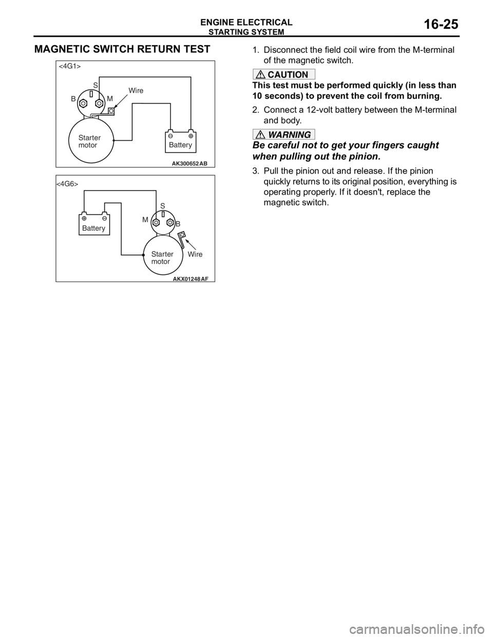
MAGNETIC SWITCH RETURN TEST
AK300652AB
<4G1>S
B MWire
Battery
Starter
motor
AKX01248
<4G6>
SB
M
Battery
Starter
motorWire
AF
1.
Disco nnect the field coil wire f r om th e M-te rmin al
o f the magnet ic switch.
CAUTION
This test must be performed quickly (in less than
10 seconds) to prevent the coil from burning.
2. Connect a 12-volt battery between the M-terminal and body.
WARNING
Be careful not to ge t your fingers caught
when pulling out the pinion.
3. Pull the pinion out and release. If the pinion
quickly returns to its original position, everything is
operating properly. If it doesn't, replace the
magnetic switch.
Page 92 of 800
IGNITION SYSTEM
ENGINE ELECTRICAL16-30
IGNITION SYSTEM
GENERAL INFORMATIONM1163000100294
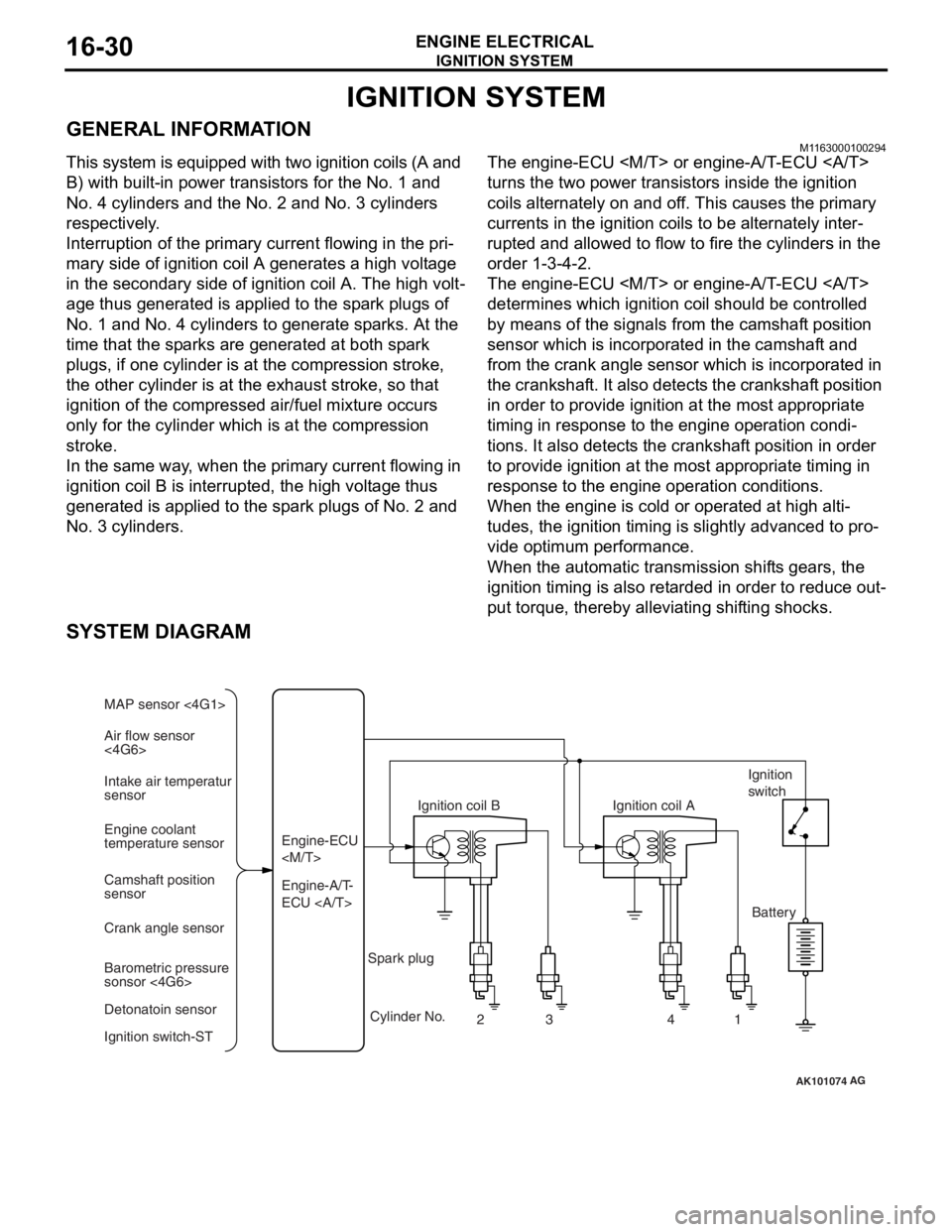
This system is equipped with two ignition coils (A and
B) with built-in power transistors for the No. 1 and
No. 4 cylinders and the No. 2 and No. 3 cylinders
respectively.
Interruption of the primary current flowing in the pri-
mary side of ignition coil A generates a high voltage
in the secondary side of ignition coil A. The high volt
-
age thus generated is applied to the spark plugs of
No. 1 and No. 4 cylinders to generate sparks. At the
time that the sparks are generated at both spark
plugs, if one cylinder is at the compression stroke,
the other cylinder is at the exhaust stroke, so that
ignition of the compressed air/fuel mixture occurs
only for the cylinder which is at the compression
stroke.
In the same way, when the primary current flowing in
ignition coil B is interrupted, the high voltage thus
generated is applied to the spark plugs of No. 2 and
No. 3 cylinders.
The engine-ECU
turns the two power transistors inside the ignition
coils alternately on and off. This causes the primary
currents in the ignition coils to be alternately inter
-
rupted and allowed to flow to fire the cylinders in the
order 1-3-4-2.
The engine-ECU
determines which ignition coil should be controlled
by means of the signals from the camshaft position
sensor which is incorporated in the camshaft and
from the crank angle sensor which is incorporated in
the crankshaft. It also detects the crankshaft position
in order to provide ignition at the most appropriate
timing in response to the engine operation condi
-
tions. It also detects the crankshaft position in order
to provide ignition at the most appropriate timing in
response to the engine operation conditions.
When the engine is cold or operated at high alti-
tudes, the ignition timing is slightly advanced to pro-
vide optimum performance.
When the automatic transmission shifts gears, the
ignition timing is also retarded in order to reduce out
-
put torque, thereby alleviating shifting shocks.
SYSTEM DIAGRAM
AK101074
Air flow sensor
<4G6> MAP sensor <4G1>
Intake air temperatur
sensor
Engine coolant
temperature sensor
Camshaft position
sensor
Crank angle sensor
Barometric pressure
sonsor <4G6>
Detonatoin sensor
Ignition switch-ST Engine-A/T-
ECU Engine-ECU
Ignition coil B
Cylinder No. 23 4
AG
1
Spark plug Ignition coil A
Ignition
switch
Battery
Page 99 of 800
IGNITION SYSTEM
ENGINE ELECTRICAL16-37
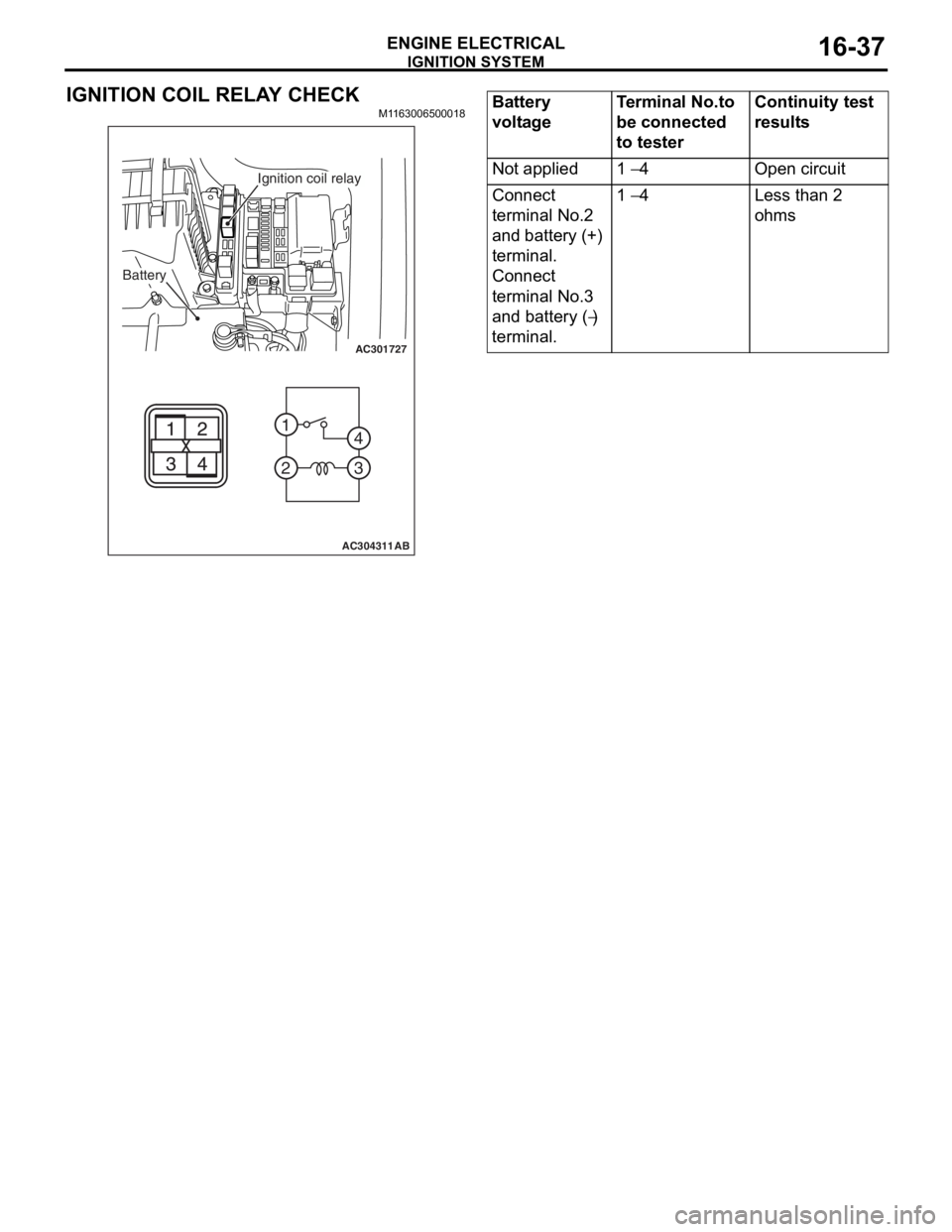
IGNITION COIL RELAY CHECK
M1163006500018
AC301727
2 1
3
4
AC304311AB
Battery
Ignition coil relay
Battery
voltageTerminal No.to
be connected
to testerContinuity test
results
Not applied1 − 4Open circuit
Connect
terminal No.2
and battery (+)
terminal.
Connect
terminal No.3
and battery (
−)
terminal.
1 − 4Less than 2
ohms