battery MITSUBISHI LANCER 2006 Owner's Manual
[x] Cancel search | Manufacturer: MITSUBISHI, Model Year: 2006, Model line: LANCER, Model: MITSUBISHI LANCER 2006Pages: 800, PDF Size: 45.03 MB
Page 116 of 800
EMISSION CONTROL
ENGINE AND EMISSION CONTROL17-10
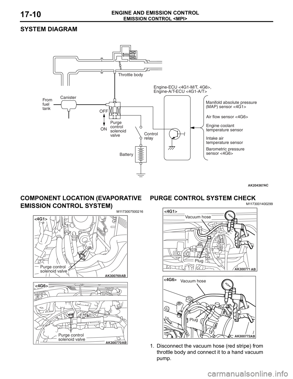
SYSTEM DIAGRAM
AK204367AC
Throttle body
Canister
From
fuel
tank
OFF
ON Purge
control
solenoid
valve
Control
relay
Battery Engine-ECU <4G1-M/T, 4G6>,
Engine-A/T-ECU <4G1-A/T>
Air flow sensor <4G6>Engine coolant
temperature sensor
Intake air
temperature sensor
Barometric pressure
sensor <4G6>
Manifold absolute pressure
(MAP) sensor <4G1>
COMPONENT LOCA
TION (EV A PORA TIVE
EMISSION CONTROL SYSTEM)
M1173 0075 0021 6
AK300769
<4G1>
AB
Purge control
solenoid valve
AK300770
<4G6>
AB
Purge control
solenoid valve
PURGE CONTROL SYSTEM CHECK
M1173 0014 0029 9
AK300771
<4G1>
AB
Plug
Vacuum hose
AK300772
<4G6>
AB
Plug
Vacuum hose
1.Disco nnect the vacu um h o se (re d str i pe) fro m
th rottle body and conne ct it to a h and vacu um
pu m p .
Page 117 of 800
EMISSION CONTROL
ENGINE AND EMISSION CONTROL17-11
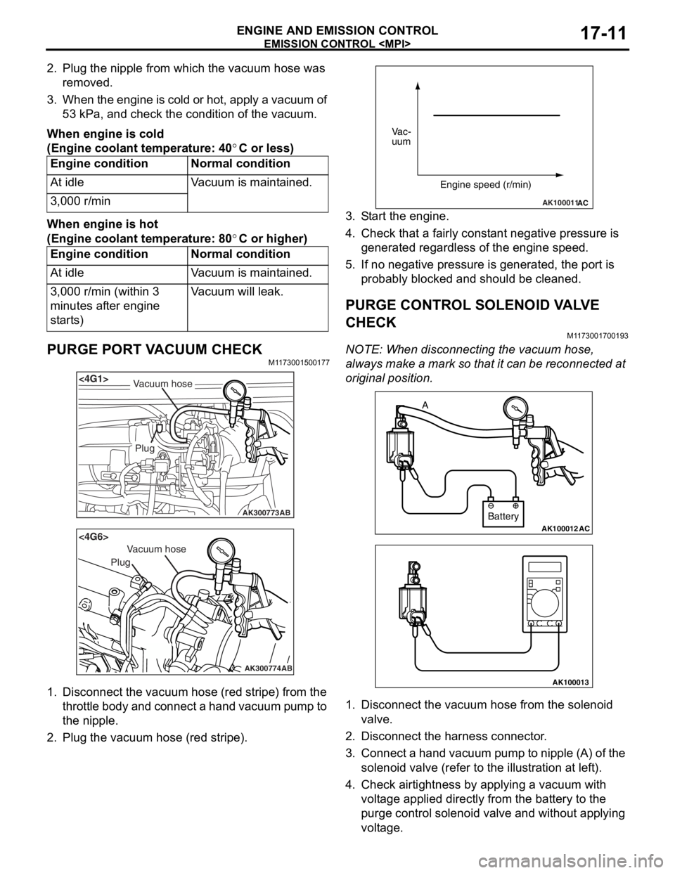
2. Plug the nipple from which the vacuum hose was removed.
3. When the engine is cold or hot, apply a vacuum of 53 kPa, and check the condition of the vacuum.
When engine is cold
(Engine coolant temperature: 40°C or less)
Engine conditionNormal condition
At idleVacuum is maintained.
3,000 r/min
When engine is hot
(Engine coolant temperature: 80°C or higher)
Engine conditionNormal condition
At idleVacuum is maintained.
3,000 r/min (within 3
minutes after engine
starts)Vacuum will leak.
PURGE PORT VACUUM CHECKM1173001500177
AK300773
<4G1>
AB
Plug
Vacuum hose
AK300774
<4G6>
AB
Plug
Vacuum hose
1.Disco nnect th e vacuum ho se (red st ripe) from the
throttle body and connect a hand vacuum pump to
th e nip p le.
2.Plu g the vacuum hose (red stripe).
AK100011AC
Vac-
uum
Engine speed (r/min)
3.S t art the engine.
4.Check t hat a f a irly co nst ant n egative p r essure is
g enerate d regard l ess of the en gine spee d.
5.If no neg ative pressur e is genera t ed, th e port is
p r obably blocked an d sh ould be cleane d.
PURGE CONTROL SOLENOID VA L V E
CHECK
M1173 0017 0019 3
NOTE: Whe n discon nect i ng th e va cuum hose,
always make a mark so th at it can be reconnected at
original p o sition.
AK100012AC
Battery
A
AK100013
1.
Disco nnect the vacu um h o se f r om th e solenoid
valve.
2.Disco nnect the ha rness connector .
3.Con nect a ha nd vacu um pump to nipp le (A) of the
solen o id valve (ref e r to th e ill ust r ation at le f t ).
4.Check a i rtig htness b y app lying a vacuum with
volt age applied d i rectly from t he batt e ry to the
p u rge con t rol so leno id valve an d without app lying
volt age .
Page 118 of 800
Battery voltageNormal condition
AppliedVacuum leaks
Not appliedVacuum maintained
EMISSION CONTROL
ENGINE AND EMISSION CONTROL17-12
5. Measure the resistance between the terminals of the solenoid valve.
Standard value: 30 − 34 Ω (at 20°C)
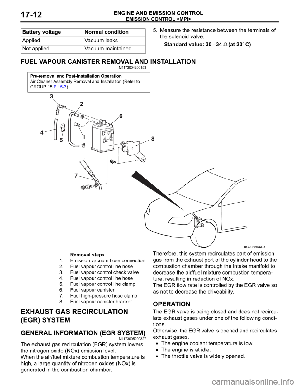
FUEL VAPOUR CANISTER RE MOVAL AND INSTALLATION
M1173004200153
Pre-removal and Post-installation Operation
Air Cleaner Assembly Removal and Installation (Refer to
GROUP 15
P.15-3).
AC208253
1
2
3
4 5 6
7 8
AD
Removal steps
1.Emission vacuum hose connection
2.Fuel vapour control line hose
3.Fuel vapour control check valve
4.Fuel vapour control line hose
5.Fuel vapour control line clamp
6.Fuel vapour canister
7.Fuel high-pressure hose clamp
8.Fuel vapour canister bracket
EXHAUST GAS RECIRCULA
T ION
(EGR) SYSTEM
GENERAL INFORMAT ION (EGR SYSTEM)
M1173 0052 0032 7
The exhaust gas recircu l atio n (EGR) system lowers
the nitrogen
oxide (NOx) emission level.
When the air/fuel mixture combus tio n temp erature is
high,
a larg e qua ntity of nitrogen oxides (NOx) is
generat
ed in the comb ustion chamb e r .
Therefor e, this syst em re circulat es p a rt o f emission
gas fro
m the e x ha ust po rt of the cylinder h ead to th e
combust
i on chamber thro ugh th e int a ke ma nifold to
decre
ase the air/fuel mixture combust i on te mpera
-
ture, resulting in redu ctio n of NOx.
The EGR flow rate is cont rolle d by the EGR valve so
as no
t to de crease the driveability .
OPERAT ION
The EGR valve is being clos ed an d does not re circu-
late ex hau st ga ses unde r one o f the fo llo wing condi-
tions.
Otherwise, th e EGR va lve is opene d an d recircul ates
exha
ust g a ses.
•The engine coolan t temperature is low .
•The engine is at idle.
•The throttle va lve is widely ope ned.
Page 119 of 800
EMISSION CONTROL
ENGINE AND EMISSION CONTROL17-13
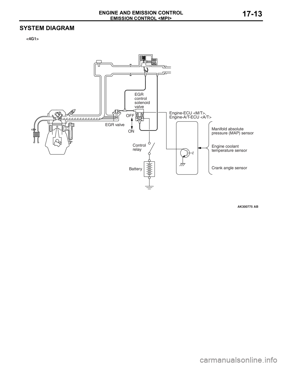
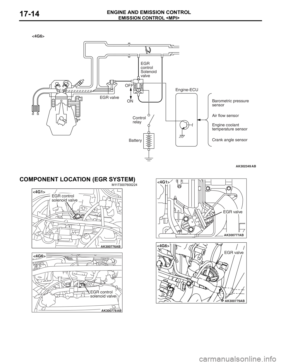
SYSTEM DIAGRAM
AK300775
Manifold absolute
pressure (MAP) sensor
Engine-ECU
Engine-A/T-ECU
Engine coolant
temperature sensor
Crank angle sensor
EGR
control
solenoid
valve
EGR valve OFF
ON Control
relay
Battery
AB
<4G1>
Page 120 of 800
AK302349AB
<4G6>EGR
control
Solenoid
valve
EGR valve OFF
ON
Control
relay
Battery Engine-ECU
Barometric pressure
sensor
Air flow sensor
Engine coolant
temperature sensor
Crank angle sensor
EMISSION CONTROL
ENGINE AND E M ISSION CON T ROL17-14
COMPONENT LOCATION (EGR SYSTEM)
M1173 0076 0022 4
AK300776
<4G1>
AB
EGR control
solenoid valve
AK300778
<4G6>
AB
EGR control
solenoid valve
AK300777
<4G1>
AB
EGR valve
AK300779AB
<4G6>
EGR valve
Page 122 of 800
EMISSION CONTROL
ENGINE AND EMISSION CONTROL17-16
5. Replace the gasket, and tighten to the specified torque.
Tightening torque:
<4G1> 21 ± 4 N⋅m
<4G6> 20 ± 2 N⋅m
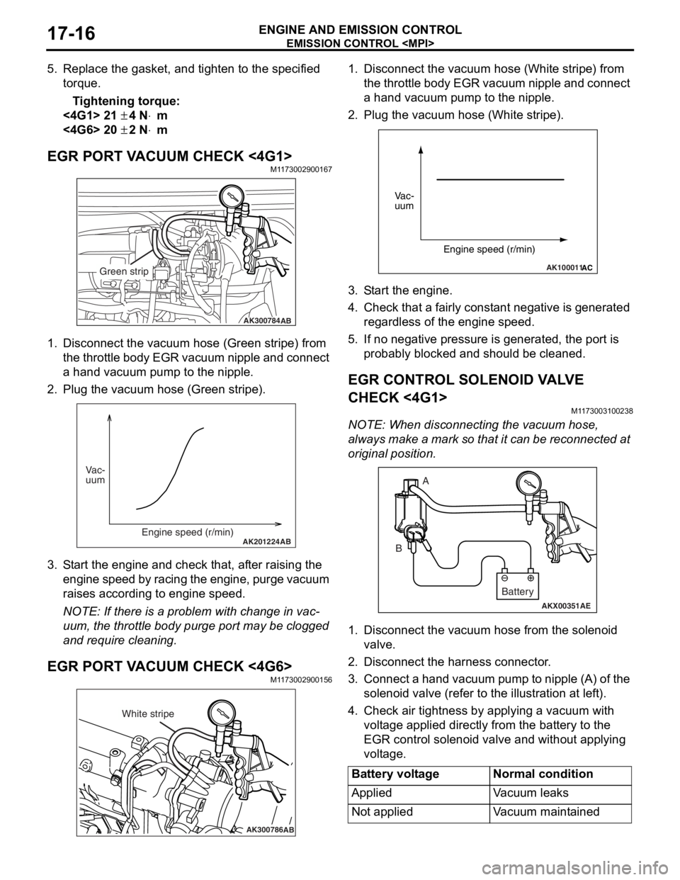
EGR PORT VACUUM CHECK <4G1>M1173002900167
AK300784AB
Green strip
1.Disco nnect the vacu um ho se (Green stripe) from
th e t h ro tt le b o d y EGR va cuu m ni pp le an d co nn ec t
a hand vacu um p u mp to the nipple.
2.Plu g the vacuum hose (Gree n stripe).
AK201224AB
Vac-
uum
Engine speed (r/min)
3.S t art the engin e and check t hat, af ter ra ising th e
engine spe ed by ra cin g the e ngine, p u rge vacuu m
raises according to engine speed.
NOTE: If ther e is a prob lem with change in vac-
uum, the t h rottle bod y p u rge port may be clo gged
an
d requ ire clean ing.
EGR PORT VA CUUM CHECK <4G6>M1173 0029 0015 6
AK300786AB
White stripe
1.Disco nnect the vacu um h o se (W hite strip e ) from
th e t h ro tt le b o d y EGR va cuu m ni pp le an d co nn ec t
a hand vacuum p u mp to the nipple.
2.Plug the vacuum hose (White stripe).
AK100011AC
Vac-
uum
Engine speed (r/min)
3.S t art the engine.
4.Check that a fairly const a nt n egative is gene rated
re gardle s s of the engine sp eed.
5.If no neg ative pressur e is genera t ed, th e port is
p r obably blocked an d sh ould be cleane d.
EGR CONTROL SOLENOID VA L V E
CHECK <
4 G1 >
M1173 0031 0023 8
NOTE: Whe n discon nect i ng th e va cuum hose,
always make a mark so th at it can be reconnected at
original p o sition.
AKX00351
A
B
AE
Battery
1. Disco nnect the vacu um h o se f r om th e solenoid
valve.
2.Disco nnect the ha rness connector .
3.Con nect a ha nd vacu um pump to nipp le (A) of the
solen o id valve (ref e r to th e ill ust r ation at le f t ).
4.Check a i r tightness b y ap plying a vacuum with
volt age applied d i rectly from t he batt e ry to the
EGR cont rol solen o id valve and withou t applyin g
volt age .
Battery voltageNormal condition
AppliedVa c u u m l e a k s
Not appliedVacuum maintained
Page 123 of 800
AKX00352
EMISSI ON CONTROL
ENGINE AND E M ISSION CON T R O L17-17
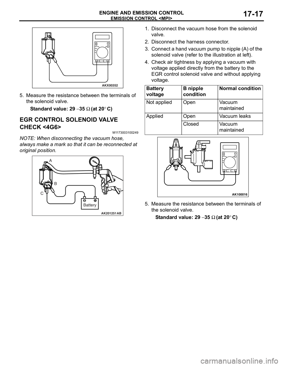
5.Measure the resist ance between the te rmin als of
th e solenoid va lve .
St andard va lue: 29 − 35 Ω (at 20°C)
EGR CONTROL SOLENOID V A L V E
CHECK <
4 G6>
M1173 0031 0024 9
NOTE: Whe n discon nect i ng th e va cuum hose,
always
make a mark so th at it can be reconnected at
original p o sition.
AK201251AB
A
B
C
Battery
1.Disco nnect the vacu um h o se f r om th e solenoid
valve.
2.Disco nnect the ha rness connector .
3.Con nect a ha nd vacu um pump to nipp le (A) of the
solen o id valve (ref e r to th e ill ust r ation at le f t ).
4.Check a i r tightness b y ap plying a vacuum with
volt age applied d i rectly from t he batt e ry to the
EGR cont rol solen o id valve and withou t applyin g
volt age .
Battery
voltageB nipple
conditionNormal condition
Not appliedOpenVacuum
maintained
AppliedOpenVacuum leaks
ClosedVacuum
maintained
AK100016
5.Measure the resist ance betwee n the te rminals of
th e so lenoid valve .
St andard va lue: 29 − 35 Ω (at 20°C)
Page 175 of 800
TRANSMISSION MOUNTING
POWER PLANT MOUNT32-5
TRANSMISSION MOUNTING
REMOVAL AND INSTALLATIONM1321001400430
CAUTION
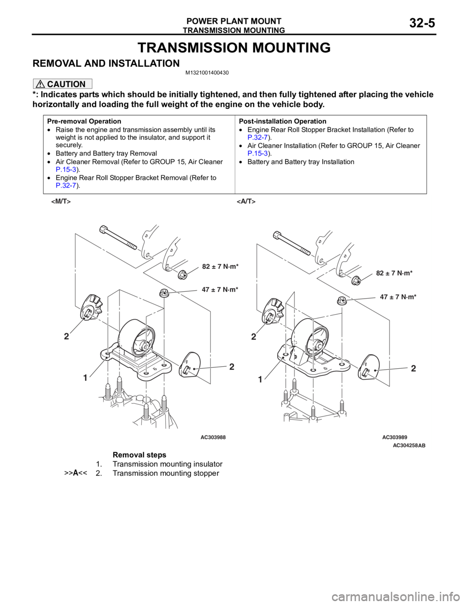
*: Indicates parts which should be initially tightened, and then fully tightened after placing the vehicle
horizontally and loading the full weight of the engine on the vehicle body.
Pre-removal Operation
•Raise the engine and transmission assembly until its
weight is not applied to the insulator, and support it
securely.
•Battery and Battery tray Removal
•Air Cleaner Removal (Refer to GROUP 15, Air Cleaner
P.15-3).
•Engine Rear Roll Stopper Bracket Removal (Refer to
P.32-7).
Post-installation Operation
•Engine Rear Roll Stopper Bracket Installation (Refer to
P.32-7).
•Air Cleaner Installation (Refer to GROUP 15, Air Cleaner
P.15-3).
•Battery and Battery tray Installation
AC303988AC303989AC304258
AB
82 ± 7 N·m*
47 ± 7 N·m*82 ± 7 N·m*
47 ± 7 N·m*
1 1
2
22
2
Removal steps
1.Transmission mounting insulator
>>A<<2.Transmission mounting stopper
Page 309 of 800
ItemIdentification
mark
Front DoorLeft door39L
Right door39R
Rear DoorLeft door40L
Right door40R
DOOR
BODY42-37
>>B<< LOWER SASH INSTALLATION
Securely insert the rear lower sash into the window
rear sash.
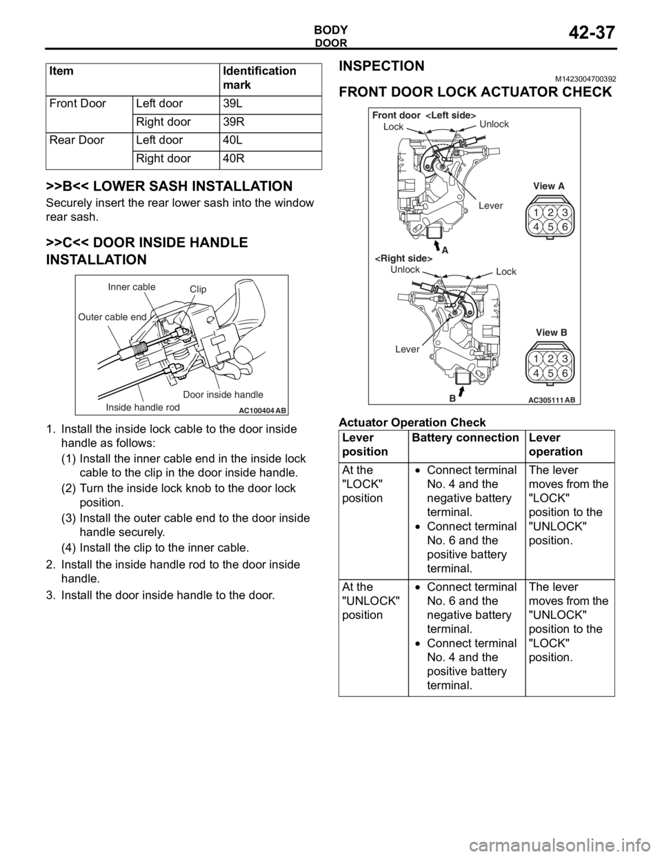
>>C<< DOOR INSIDE HANDLE
INSTALLATION
AC100404AB
Clip
Inner cable
Outer cable end
Inside handle rod Door inside handle
1.
In st all the inside lo ck cable to th e doo r inside
ha ndle as fo llo ws:
(1)I nst a ll the inne r cab l e en d in the in sid e lock
cab l e to the clip in th e door inside h andle .
(2)T urn the inside lock knob to the do or lock
positio n.
(3)I nst a ll the outer cable end to the door inside
hand le secure ly .
(4)I nst a ll the clip to the in ner cable .
2.In st all the inside han dle ro d to th e door inside
ha ndle .
3.In st all the do or inside handle to t he doo r .
INSPECTION
M14230047 0039 2
FRONT DOOR LOCK ACTUA T O R CHECK
42
53
6
1
4 2
53
6
1
AC305111B
A
AB
Lock
Unlock
View A
View B
Unlock
Lock
Front door
Lever
Ac tuator Op era t ion Check
Lever
positionBattery connectionLever
operation
At the
"LOCK"
position•Connect terminal
No. 4 and the
negative battery
terminal.
•Connect terminal
No. 6 and the
positive battery
terminal.
The lever
moves from the
"LOCK"
position to the
"UNLOCK"
position.
At the
"UNLOCK"
position•Connect terminal
No. 6 and the
negative battery
terminal.
•Connect terminal
No. 4 and the
positive battery
terminal.
The lever
moves from the
"UNLOCK"
position to the
"LOCK"
position.
Page 310 of 800
DOOR
BODY42-38
Actuator Switch Check
Lever positionTester
connectionSpecified
condition
At the "LOCK"
position1 − 2Less than 2
ohms
1 − 3Open circuit
At the "UNLOCK"
position1 − 2Open circuit
1 − 3Less than 2
ohms
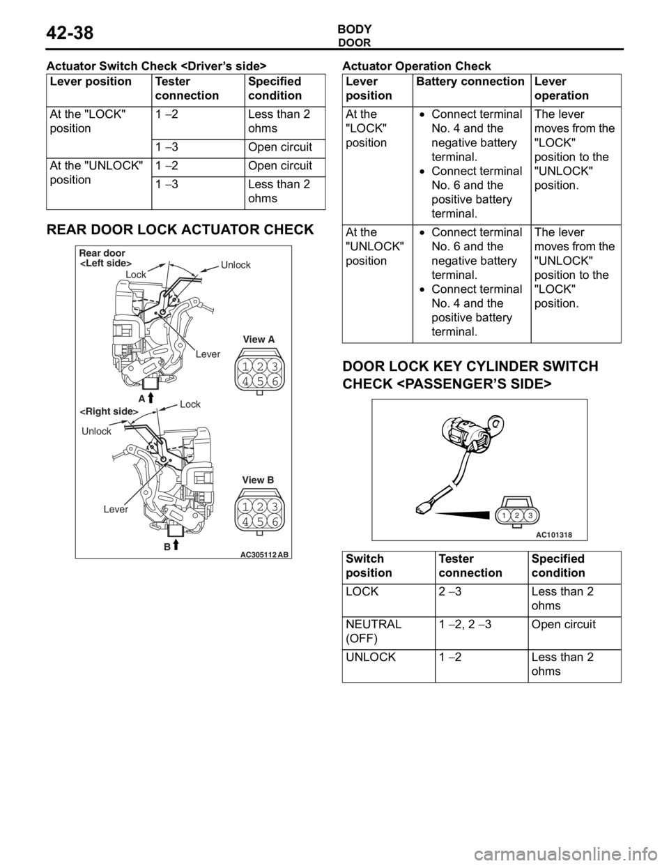
REAR DOOR LOCK ACTUATOR CHECK
23
4 1
56
23
4 1
56
AC305112B
A
AB
Rear door
Lock Unlock
View A
View B
Unlock
Lock
Lever
Ac tuator Op era t ion Check
Lever
positionBattery connectionLever
operation
At the
"LOCK"
position•Connect terminal
No. 4 and the
negative battery
terminal.
•Connect terminal
No. 6 and the
positive battery
terminal.
The lever
moves from the
"LOCK"
position to the
"UNLOCK"
position.
At the
"UNLOCK"
position•Connect terminal
No. 6 and the
negative battery
terminal.
•Connect terminal
No. 4 and the
positive battery
terminal.
The lever
moves from the
"UNLOCK"
position to the
"LOCK"
position.
DOOR LOCK KEY CYLINDER SWITCH
CHECK
AC101318
3
2
1
Switch
positionTester
connectionSpecified
condition
LOCK2 − 3Less than 2
ohms
NEUTRAL
(OFF)1 − 2, 2 − 3Open circuit
UNLOCK1 − 2Less than 2
ohms