belt MITSUBISHI LANCER 2006 User Guide
[x] Cancel search | Manufacturer: MITSUBISHI, Model Year: 2006, Model line: LANCER, Model: MITSUBISHI LANCER 2006Pages: 800, PDF Size: 45.03 MB
Page 104 of 800
IGNITION SYSTEM
ENGINE ELECTRICAL16-42
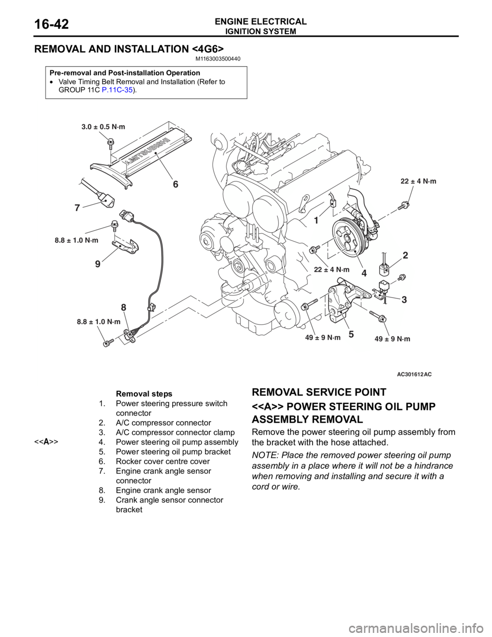
REMOVAL AND INSTALLATION <4G6>
M1163003500440
Pre-removal and Post-installation Operation
•Valve Timing Belt Removal and Installation (Refer to
GROUP 11C P.11C-35).
AC301612
8.8 ± 1.0 N·m
8
8.8 ± 1.0 N·m
9
1
22 ± 4 N·m
4
2
3
49 ± 9 N·m49 ± 9 N·m5
22 ± 4 N·m
3.0 ± 0.5 N·m
6
7
AC
Removal steps
1.Power steering pressure switch
connector
2.A/C compressor connector
3.A/C compressor connector clamp
<>4.Power steering oil pump assembly
5.Power steering oil pump bracket
6.Rocker cover centre cover
7.Engine crank angle sensor
connector
8.Engine crank angle sensor
9.Crank angle sensor connector
bracket
REMOV A L SER VICE POINT
<> POWE R STEERING OIL PUMP
ASSEMBL
Y REMOV A L
Remove the p o wer st eering oil pump assembly from
the bra
cke t with th e hose att a ched.
NOTE: Place the remo ved power st eering oil pump
assembly in a place where it will not be a hindrance
wh
en removing an d inst a lling an d secure it with a
cord or wire.
Page 231 of 800
37-1
GROUP 37
POWER STEERING
CONTENTS
GENERAL INFORMATION . . . . . . . .37-3
SERVICE SPECIFICATIONS . . . . . . .37-6
LUBRICANTS . . . . . . . . . . . . . . . . . .37-7
SEALANTS . . . . . . . . . . . . . . . . . . . .37-7
SPECIAL TOOLS . . . . . . . . . . . . . . . .37-8
ON-VEHICLE SERVICE . . . . . . . . . . .37-11
STEERING WHEEL FREE PLAY CHECK . 37-11
STEERING ANGLE CHECK . . . . . . . . . . . . 37-11
TIE ROD END BALL JOINT TURNING
TORQUE CHECK . . . . . . . . . . . . . . . . . . . . 37-12
STATIONARY STEERING EFFORT
CHECK . . . . . . . . . . . . . . . . . . . . . . . . . . . . 37-12
STEERING WHEEL RETURN TO
CENTRE CHECK . . . . . . . . . . . . . . . . . . . . 37-13
DRIVE BELT TENSION CHECK. . . . . . . . . 37-13
FLUID LEVEL CHECK . . . . . . . . . . . . . . . . 37-13
FLUID REPLACEMENT . . . . . . . . . . . . . . . 37-13
POWER STEERING SYSTEM AIR
BLEEDING . . . . . . . . . . . . . . . . . . . . . . . . . 37-14
OIL PUMP PRESSURE TEST . . . . . . . . . . 37-14
POWER STEERING PRESSURE
SWITCH CHECK . . . . . . . . . . . . . . . . . . . . . 37-15
TIE ROD END BALL JOINT DUST
COVER CHECK . . . . . . . . . . . . . . . . . . . . . 37-15
STEERING COLUMN SHAFT ASSEMBLY
SHOCK ABSORBING MECHANISM
CHECK . . . . . . . . . . . . . . . . . . . . . . . . . . . . 37-15
STEERING WHEEL . . . . . . . . . . . . . .37-17
REMOVAL AND INSTALLATION
REMOVAL AND INSTALLATION
Continued on next page
WARNINGS REGARDING SERVICING OF SUPPLEMENTAL RESTRAINT SYSTEM (SRS) EQUIPPED VEHICLES
WARNING
•Improper service or maintenance of any component of the SRS, or any SRS-related component, can lead to
personal injury or death to service personnel (from inad vertent firing of the air bag) or to the driver and
paassenger (from renderin g the SRS inoperative).
•Service or maintenance of any SRS component or SRS-related component must be performed only at an
authorized MITSUBISHI dealer.
•MITSUBISHI dealer personnel must thoroughly review th is manual, and especially its GROUP 52B - Supplemental
Restraint System (SRS) before begi nning any service or maintenance of any component of the SRS or any
SRS-related component.
NOTE
The SRS includes the following components: SRS air bag control unit, SRS warning light, front impact sensors, air bag module,
clock spring, and interconnecting wiring. Other SRS-related components (that may have to be removed/installed in connection
with SRS service or maintenance) are indicated in the table of contents by an asterisk (*).
Page 243 of 800
ON-VEHICLE SERVICE
POWER STEERING37-13
STEERING WHEEL RETURN TO CENTRE
CHECK
M1372001800317
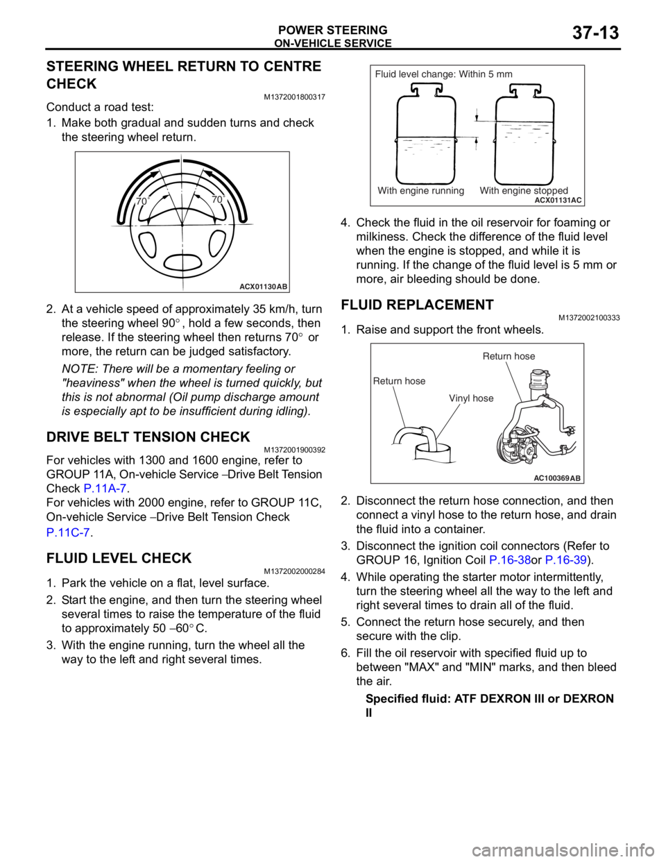
Conduct a road test:
1. Make both gradual and sudden turns and check the steering wheel return.
ACX01130 AB
70˚ 70˚
2.
At a vehicle sp eed of a pproxima t ely 35 km/h, turn
th e ste e ring wh eel 9 0
°, ho ld a few se cond s, the n
release. If th
e ste
e
ring
wh eel t hen ret u rns 7 0
° or
more, th
e return
can
be ju
dged satisfactory
.
NOTE: There will be a mome nt a r y fee lin g or
"he
a
viness" when t he wheel is turned quickly , but
th
is is n o t abno rmal (Oil pu mp discharge amou nt
is especially a p t to b e insufficie n t during id lin g).
DRIVE BELT TENSION CHECK
M13720019 0039 2
For vehicles with 13 00 and 1600 engin e , refer to
GROUP 1
1 A, On-vehicle Service
− Drive Belt T ension
Che
c
k
P.11A-7.
For veh i cles wit h 2000 e ngin e , refer to GROUP 1 1 C,
On-vehicle Se
rvice
− Drive Belt Te nsion Check
P.1 1 C - 7.
FLUID LEVEL CHECK
M13720020 0028 4
1.Park the vehicle on a f l at, leve l su rface .
2.S t art the engine, and t hen tu rn the ste e ring wheel
seve ral times to raise the temperat ure of th e flu i d
to approximately 50
− 60°C.
3.With the engine run n ing, turn the wheel all the
way to the lef t an d righ t several times.
ACX01131With engine running With engine stoppedAC
Fluid level change: Within 5 mm
4.Check t he flu i d in the oil r e servoir f o r foaming or
milkine s s. Check the d i f f e r ence of the fluid le vel
when the e ngine is stop ped, an d while it is
ru nning . If the chan ge of th e fluid le vel is 5 mm or
more, a i r bleedin g sh ould be don e.
FLUID REPLACEMENT
M13720021 0033 3
1.Raise a nd su pport t he fron t wheels.
AC100369AB
Return hoseReturn hose
Vinyl hose
2. Disco nnect the re turn hose connection , and then
conne ct a vinyl hose to the re turn h o se, and drain
th e flu i d into a cont ain e r .
3.Disco nnect the ignition coil con necto rs (Refe r to
GROUP 16, Ignition Coil
P.16-38or P.16-39).
4.Wh ile operat ing th e st arter moto r inter m itt ently ,
tu rn the steering whee l all the wa y to t he le f t a nd
right seve ral times to dra i n all of the fluid.
5.Conn ect the retu rn hose se curely , and then
secu re with t he clip.
6.Fill the oil reservo i r with specified fluid u p to
b e tween "MAX" and "MIN" marks, and then bleed
th e air .
Specified fluid: A TF DEXRON III or DEXRON
II
Page 265 of 800
POWER STEERING OIL PUMP ASSEMBLY
POWER STEERING37-35
TIE ROD END BALL JOINT DUST COVER
REPLACEMENT
M1372008200327
If the dust cover is damaged accidentally during
service work, replace the dust cover as follows:
AC001012AB
MB990776
1.App l y specified grea se to the lip an d inside of the
d u st c o ve r .
Specified grease:
Mu l t i p u r po se g r ea se SAE J3 10 , NL GI No .2 or
equival
ent
2.Drive in the d u st cover with special tool f r ont axle
b a se (MB9907 76) unt il it is fully seated .
3.Check t he dust co ver f o r cracks or da mage by
p u shing it with your finger .
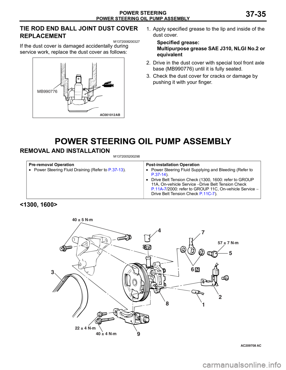
POWER STEERING OIL PUMP ASSEMBL Y
REMOVA L AND INST ALLA TIONM13720052 0029 8
Pre-removal Operation
•Power Steering Fluid Draining (Refer to P.37-13).
Post-installation Operation
•Power Steering Fluid Supplying and Bleeding (Refer to
P.37-14).
•Drive Belt Tension Check (1300, 1600: refer to GROUP
11A, On-vehicle Service
− Drive Belt Tension Check
P.11A-7/2000: refer to GROUP 11C, On-vehicle Service − Drive Belt Tension Check P.11C-7).
<1300, 1600>
AC209708
87
1 2
3 4
5
6
57 ± 7 N·m
40 ± 4 N·m
22 ± 4 N·m
N
9
40 ± 5 N·m
AC
Page 266 of 800
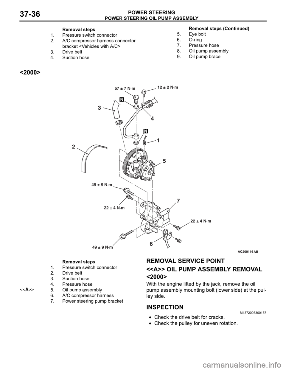
Removal steps
1.Pressure switch connector
2.A/C compressor harness connector
bracket
3.Drive belt
4.Suction hose
5.Eye bolt
6.O-ring
7.Pressure hose
8.Oil pump assembly
9.Oil pump brace
POWER STEERING OIL PUMP ASSEMBLY
POWER STEERING37-36
<2000>
AC200116AB
22 ± 4 N·m
12 ± 2 N·m
22 ± 4 N·m
49 ± 9 N·m 57 ± 7 N·m
1
5
4
3
6
2
7
49 ± 9 N·m
Removal steps
1.Pressure switch connector
2.Drive belt
3.Suction hose
4.Pressure hose
<>5.Oil pump assembly
6.A/C compressor harness
7.Power steering pump bracket
REMOVA L SER VICE POINT
<> OIL PUMP ASSEMBL Y REMOV A L
<2000>
With the eng ine lif t ed by the jack, remove the o il
pump
assembly mounting b o lt (lower side) a t the pul
-
ley side .
INSPECTIONM13720053 0018 7
•Check the drive belt for cracks.
•Check th e pulley for une ven r o t a tion.
Remova l st ep s ( C ont inu e d)
Page 305 of 800
AC503181
NOTE
: Clip positions
: Claw positions
View A
BB
BB
C
C C
CC
C C
C
Section B - B
Door trim
Clip
Section C - C
AB
Door trim
Claw
7
77
7
A
AC503182
NOTE
: Clip positions
: Claw positions
E
E
EE
F
F F
F F
F F
F
Section E - E View D
Door trim
Clip
Section F - F
Door trim
Claw
D
7
7
7
AB
7
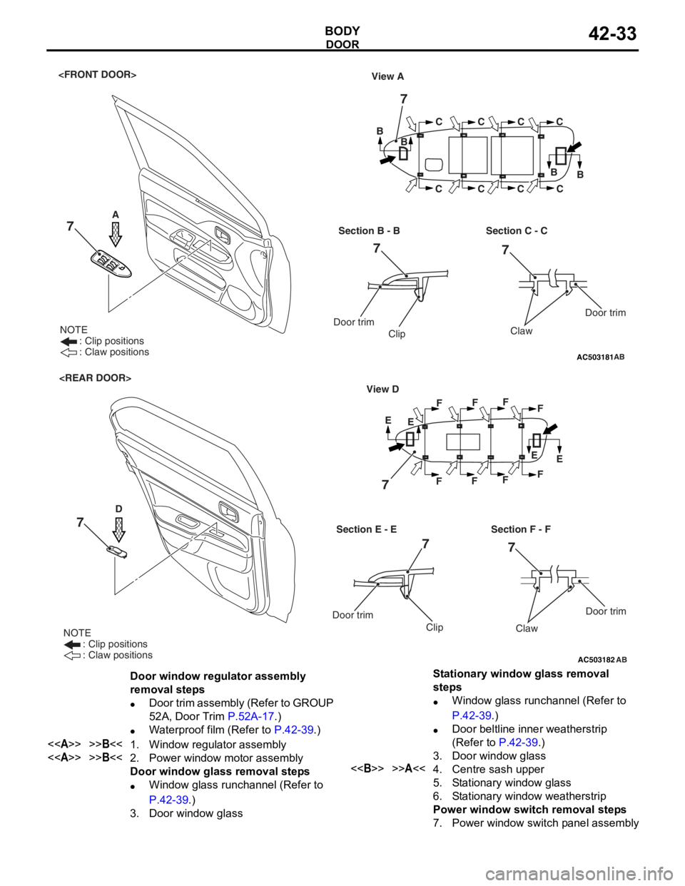
Door window regulator assembly
removal steps
•Door trim assembly (Refer to GROUP
52A, Door Trim
P.52A-17.)
•Waterproof film (Refer to P.42-39.)
<>>>B<<1.Window regulator assembly
<>>>B<<2.Power window motor assembly
Door window glass removal steps
•Window glass runchannel (Refer to
P.42-39.)
3.Door window glass
Stationary window glass removal
steps
•Window glass runchannel (Refer to
P.42-39.)
•Door beltline inner weatherstrip
(Refer to
P.42-39.)
3.Door window glass
<>>>A<<4.Centre sash upper
5.Stationary window glass
6.Stationary window weatherstrip
Power window switch removal steps
7.Power window switch panel assembly
DOOR
BO
D Y42-33
Page 311 of 800
DOOR
BODY42-39
WINDOW GLASS RUNCHANNEL AND
DOOR OPENING WEATHERSTRIP
REMOVAL AND INSTALLATION
M1423003100290
AC304409AB
Section A – A
Sealant: 3M ATD Part No.8633 or equivalent Door
: Sectional view of
clip position
: Sectional view of clip position
6
2
1
4
365
A A
1
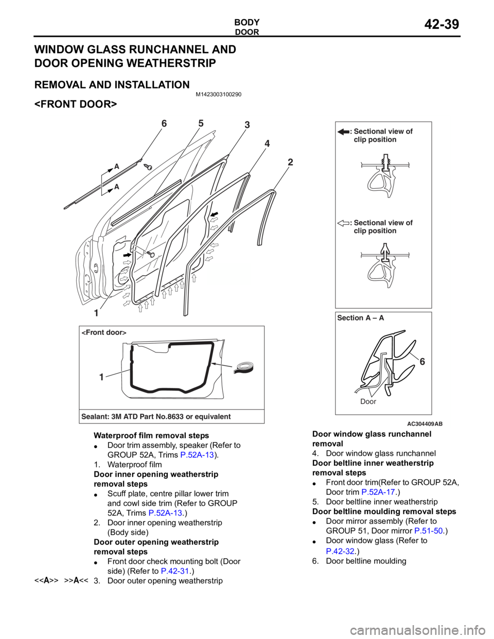
Waterproof film removal steps
•Door trim assembly, speaker (Refer to
GROUP 52A, Trims
P.52A-13).
1.Waterproof film
Door inner opening weatherstrip
removal steps
•Scuff plate, centre pillar lower trim
and cowl side trim (Refer to GROUP
52A, Trims
P.52A-13.)
2.Door inner opening weatherstrip
(Body side)
Door outer opening weatherstrip
removal steps
•Front door check mounting bolt (Door
side) (Refer to
P.42-31.)
<>>>A<<3.Door outer opening weatherstrip
Door window glass runchannel
removal
4.Door window glass runchannel
Door beltline inner weatherstrip
removal steps
•Front door trim(Refer to GROUP 52A,
Door trim
P.52A-17.)
5.Door beltline inner weatherstrip
Door beltline moulding removal steps
•Door mirror assembly (Refer to
GROUP 51, Door mirror
P.51-50.)
•Door window glass (Refer to
P.42-32.)
6.Door beltline moulding
Page 312 of 800
DOOR
BODY42-40
AC304418AB
Section A – ADoor
: Sectional view of clip position
: Sectional view of clip position
7
2
4
5
7
A A
3
Section B – B
Door
4
3
6
BB
Sealant: 3M ATD Part No.8633 or equivalent
1
1
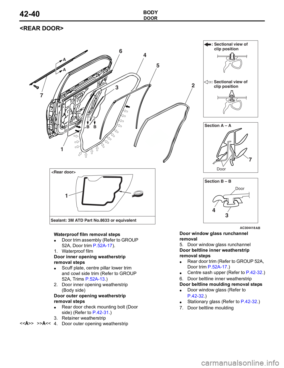
Waterproof film removal steps
•Door trim assembly (Refer to GROUP
52A, Door trim
P.52A-17).
1.Waterproof film
Door inner opening weatherstrip
removal steps
•Scuff plate, centre pillar lower trim
and cowl side trim (Refer to GROUP
52A, Trims
P.52A-13.)
2.Door inner opening weatherstrip
(Body side)
Door outer opening weatherstrip
removal steps
•Rear door check mounting bolt (Door
side) (Refer to
P.42-31.)
3.Retainer weatherstrip
<>>>A<<4.Door outer opening weatherstrip
Door window glass runchannel
removal
5.Door window glass runchannel
Door beltline inner weatherstrip
removal steps
•Rear door trim (Refer to GROUP 52A,
Door trim
P.52A-17.)
•Centre sash upper (Refer to P.42-32.)
6.Door beltline inner weatherstrip
Door beltline moulding removal steps
•Door window glass (Refer to
P.42-32.)
•Stationary glass (Refer to P.42-32.)
7.Door beltline moulding
Page 349 of 800
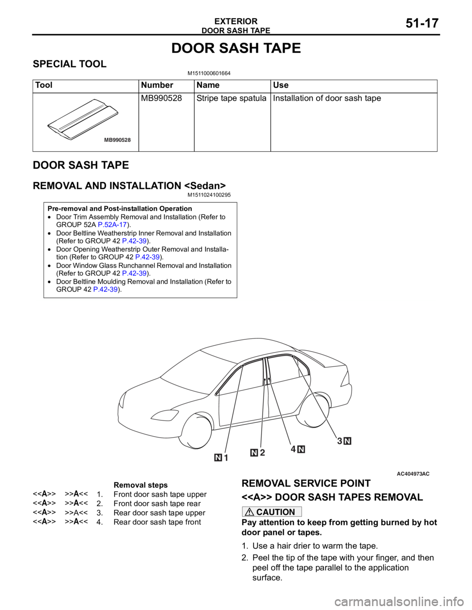
DOOR SASH TAPE
EXTERIOR51-17
DOOR SASH TAPE
SPECIAL TOOLM1511000601664
ToolNumberNameUse
MB990528
MB990528Stripe tape spatulaInstallation of door sash tape
DOOR SASH TA PE
REMOVA L AND INST ALLA TION
Pre-removal and Post-installation Operation
•Door Trim Assembly Removal and Installation (Refer to
GROUP 52A
P.52A-17).
•Door Beltline Weatherstrip Inner Removal and Installation
(Refer to GROUP 42
P.42-39).
•Door Opening Weatherstrip Outer Removal and Installa-
tion (Refer to GROUP 42 P.42-39).
•Door Window Glass Runchannel Removal and Installation
(Refer to GROUP 42
P.42-39).
•Door Beltline Moulding Removal and Installation (Refer to
GROUP 42
P.42-39).
AC404973
124
3
N
NN
N
AC
Removal steps
<>>>A<<1.Front door sash tape upper
<>>>A<<2.Front door sash tape rear
<>>>A<<3.Rear door sash tape upper
<>>>A<<4.Rear door sash tape front
REMOVA L SER VICE POINT
<> DOOR SASH T A PES REMOV A L
CAUTION
Pay attention to keep from getting burned by hot
door panel or tapes.
1. Use a hair drier to warm the tape.
2. Peel the tip of the tape with your finger, and then
peel off the tape parallel to the application
surface.
Page 353 of 800
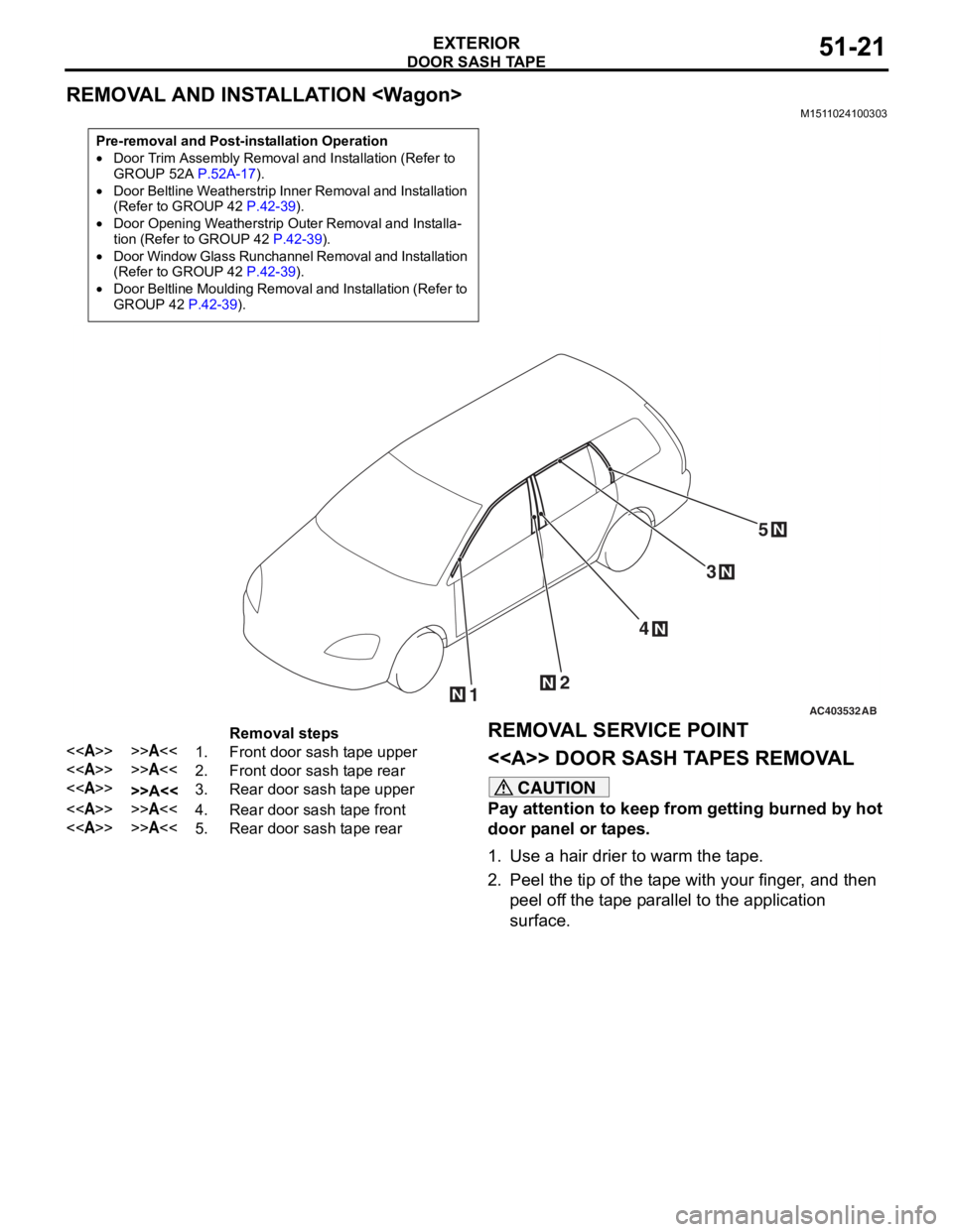
DOOR SASH TAPE
EXTERIOR51-21
REMOVAL AND INSTALLATION
M1511024100303
Pre-removal and Post-installation Operation
•Door Trim Assembly Removal and Installation (Refer to
GROUP 52A P.52A-17).
•Door Beltline Weatherstrip Inner Removal and Installation
(Refer to GROUP 42 P.42-39).
•Door Opening Weatherstrip Outer Removal and Installa-tion (Refer to GROUP 42 P.42-39).
•Door Window Glass Runchannel Removal and Installation
(Refer to GROUP 42 P.42-39).
•Door Beltline Moulding Removal and Installation (Refer to
GROUP 42 P.42-39).
AC40353212
4
3
N
N
N
N
5N
AB
Removal steps
<>>>A<<1.Front door sash tape upper
<>>>A<<2.Front door sash tape rear
<>>>A<<3.Rear door sash tape upper
<>>>A<<4.Rear door sash tape front
<>>>A<<5.Rear door sash tape rear
REMOVA L SER VICE POINT
<> DOOR SASH T A PES REMOV A L
CAUTION
Pay attention to keep from getting burned by hot
door panel or tapes.
1. Use a hair drier to warm the tape.
2. Peel the tip of the tape with your finger, and then
peel off the tape parallel to the application
surface.