block MITSUBISHI LANCER 2006 User Guide
[x] Cancel search | Manufacturer: MITSUBISHI, Model Year: 2006, Model line: LANCER, Model: MITSUBISHI LANCER 2006Pages: 800, PDF Size: 45.03 MB
Page 381 of 800
DOOR MIRROR
EXTERIOR51-49
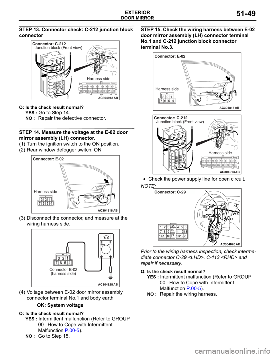
STEP 13. Connector check: C-212 junction block
connector
AC304913
21716151718
201912345
623 222425282627981011141213
Connector: C-212
Harness side
AB
Junction block (Front view)
Q : Is the check result normal?
YES : Go to S t ep 14 .
NO : Repa ir the defective connector .
STEP 14 . Me asure the volt age at the E-02 door
mirror a
ssembl y (LH) conne ctor .
(1)T urn t he ig nition switch to the ON positio n.
(2)R ear win dow defo gger switch : ON
AC304818
Connector: E-02
Harness side
AB
(3) D isconn ect t he co nnector , an d me asure at the
wiring harn e ss side.
AC304828
Connector E-02(harness side)
AB
(4) V olt a g e between E-02 doo r mirror assembly
co nnector termina l No.1 a nd bod y ea rth
OK: System vo lt age
Q: Is the check result normal?
YES : Intermittent ma lfun ctio n (Refer to GROUP
00
− Ho w t o Cope wit h Intermitte nt
Malfunction
P.00-5).
NO : Go to S t ep 15 .
STEP 1 5 . Chec k the wiring ha rnes s betwe en E-02
door mirror assem
bly (LH) con nector termina l
No.
1 and C-21 2 junctio n block connec tor
terminal No.3
.
AC304818
Connector: E-02
Harness side
AB
AC304913
21 716151718
201912345
623 222425282627981011141213
Connector: C-212
Harness side
AB
Junction block (Front view)
•Check th e power supply line fo r open circuit.
NOTE:
AC304820
Connector: C-29
AB
Prior to the wiring harness insp ection, check interme-
diate connector C-29
rep
a ir if necessary .
Q:Is t h e che c k r esu lt n o rmal?
YES : Intermittent malfun ctio n (Refer to GROUP
00
− Ho w to Cope wit h Intermitte nt
Ma
lfunction
P.00-5).
NO : Repa ir th e wirin g harne ss.
Page 394 of 800
AC501784AB
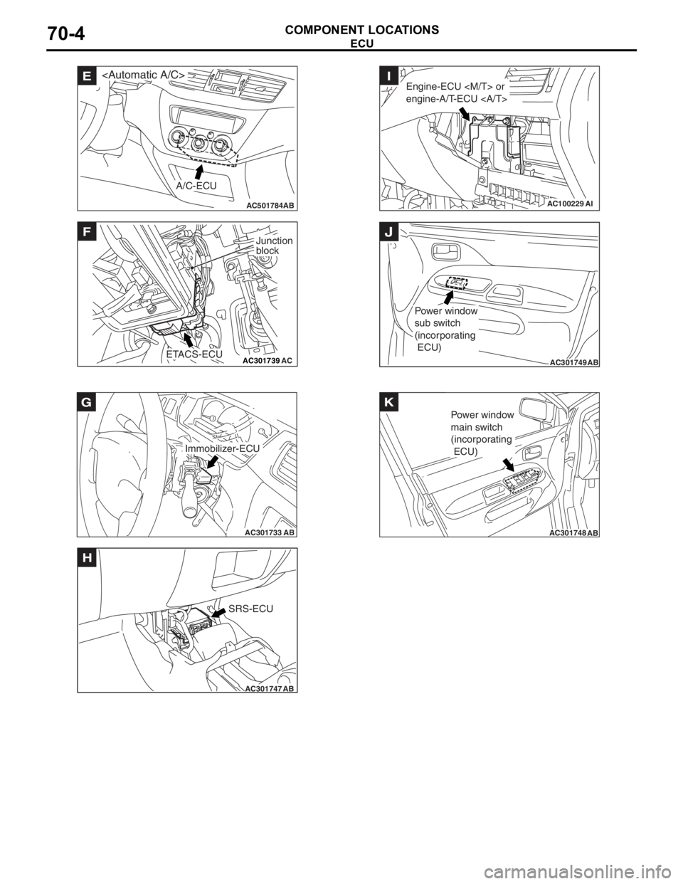
E
A/C-ECU
AC301739AC
F
ETACS-ECU
Junction
block
AC301733AB
Immobilizer-ECU
G
AC301747AB
SRS-ECU
H
AC100229AI
Engine-ECU
engine-A/T-ECU I
AC301749AB
Power window
sub switch
(incorporating
ECU)
J
AC301748AB
Power window
main switch
(incorporating
ECU)
K
ECU
COMPONENT LOCA
TIONS70-4
Page 401 of 800
FUSIBLE LINK AND FUSE
COMPONENT LOCATIONS70-11
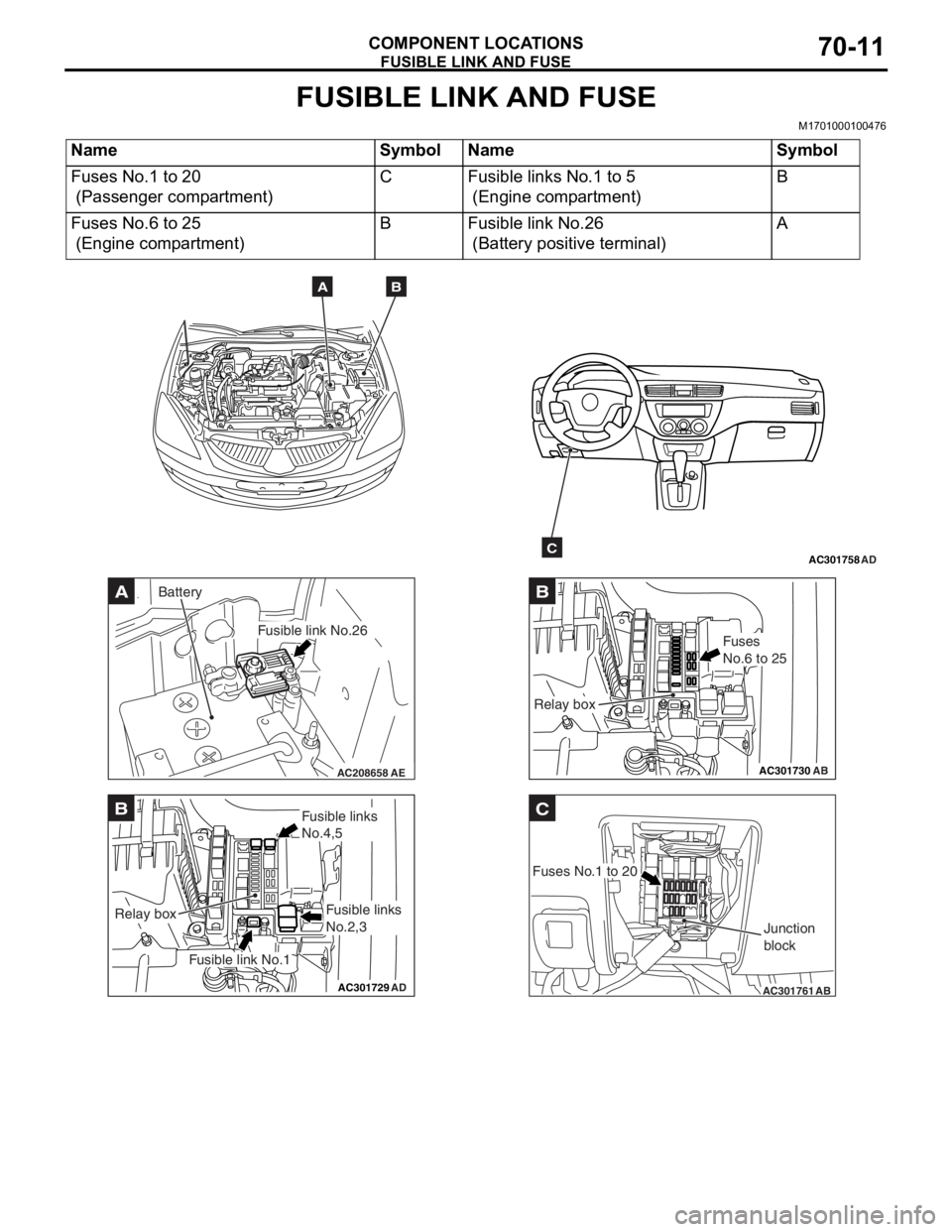
FUSIBLE LINK AND FUSE
M1701000100476
NameSymbolNameSymbol
Fuses No.1 to 20
(Passenger compartment)
CFusible links No.1 to 5
(Engine compartment)
B
Fuses No.6 to 25
(Engine compartment)
BFusible link No.26
(Battery positive terminal)
A
AC301758AD
AB
C
AC208658AE
A
Fusible link No.26
Battery
AC301729AD
B
Fusible link No.1
Relay box
Fusible links
No.4,5
Fusible links
No.2,3
AC301730
B
AB
Fuses
No.6 to 25
Relay box
AC301761
C
AB
Fuses No.1 to 20Junction
block
Page 407 of 800
AC300427
1
AD
AC301737AB
2 3
,
2
3
AC300429 AB
2
Junction
block
AC206768 AD
3
16
,
3
16
AC301742 AB
4
Glove box
AC301741AB
5
Diagnosis
connector
AC100195
6
AC
Windshield
wiper arm
AC212109AC
6Steering column
shaft assembly
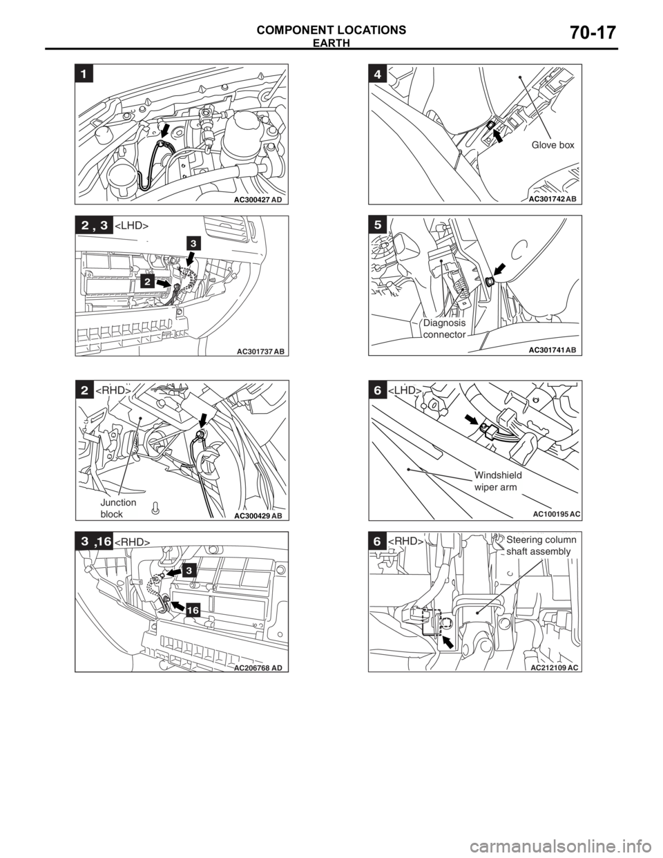
EARTH
COMPONENT LOCA
TIONS70-17
Page 409 of 800
AC300436AC
15
SRS-ECU
AC208871AC
Junction block16
AC301210
17
AC
Rear seatback
hook (LH)
AC300440
17
AC
Rear
speaker
(LH)
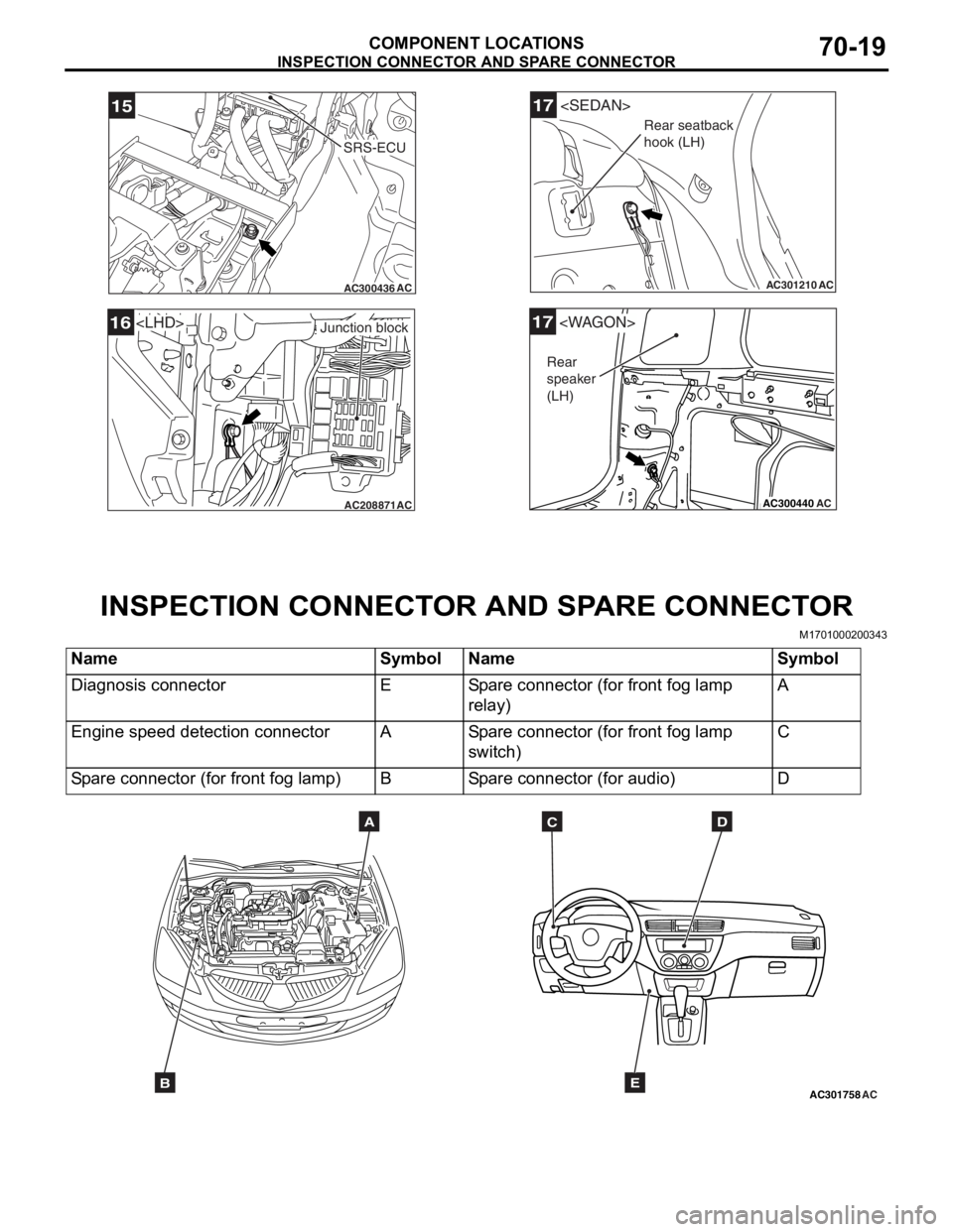
INSPECTION CONN ECT O R AND SP ARE CONNEC T OR
COMPONENT LOCATIONS70-19
IN SPECTION CONNECT OR AND SP ARE CONNECT OR
M17010002 0034 3
NameSymbolNameSymbol
Diagnosis connectorESpare connector (for front fog lamp
relay)A
Engine speed detection connectorASpare connector (for front fog lamp
switch)C
Spare connector (for front fog lamp)BSpare connector (for audio)D
AC301758ACB
ADC
E
Page 441 of 800
AC302010AC
(Front view)(Rear view)
C-208 C-209 C-210 C-211
C-212
C-213
C-214
C-215
C-217
C-218
C-219
C-220 C-221 C-222 C-223 C-224 C-225
C-226
C-227
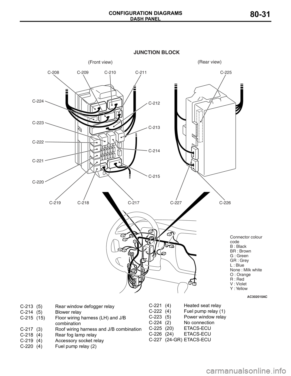
JUNCTION BLOCK
Connector colour
code
B : Black
BR : Brown
G : Green
GR : Grey
L : Blue
None : Milk white
O : Orange
R : Red
V : Violet
Y : Yellow
C-213(5)Rear window defogger relay
C-214(5)Blower relay
C-215(15)Floor wiring harness (LH) and J/B
combination
C-217(3)Roof wiring harness and J/B combination
C-218(4)Rear fog lamp relay
C-219(4)Accessory socket relay
C-220(4)Fuel pump relay (2)
C-221(4)Heated seat relay
C-222(4)Fuel pump relay (1)
C-223(5)Power window relay
C-224(2)No connection
C-225(20)ETACS-ECU
C-226(24)ETACS-ECU
C-227(24-GR)ETACS-ECU
DASH P ANEL
CONF IGURA TION D I A G RA MS80-31
Page 447 of 800
AC302011AC
(Front view)(Rear view)
C-208 C-209 C-210 C-211
C-212
C-213
C-214
C-216
C-217
C-218
C-219
C-220 C-221 C-222 C-223 C-224 C-225
C-226
C-227
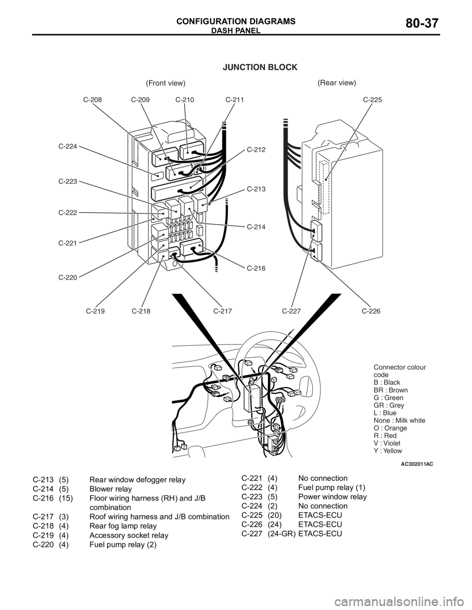
JUNCTION BLOCK
Connector colour
code
B : Black
BR : Brown
G : Green
GR : Grey
L : Blue
None : Milk white
O : Orange
R : Red
V : Violet
Y : Yellow
C-213(5)Rear window defogger relay
C-214(5)Blower relay
C-216(15)Floor wiring harness (RH) and J/B
combination
C-217(3)Roof wiring harness and J/B combination
C-218(4)Rear fog lamp relay
C-219(4)Accessory socket relay
C-220(4)Fuel pump relay (2)
C-221(4)No connection
C-222(4)Fuel pump relay (1)
C-223(5)Power window relay
C-224(2)No connection
C-225(20)ETACS-ECU
C-226(24)ETACS-ECU
C-227(24-GR)ETACS-ECU
DASH P ANEL
CONF IGURA TION D I A G RA MS80-37
Page 482 of 800

CENTRALIZED JUNCTION
CIRCUIT DIAGRAMS90-18
CENTRALIZED JUNCTION
M1901000301477
FUSIBLE LINK AND FUSE
ENGINE COMPARTMENT
No.Power supply circuitNameRated
capacity (A)Housing
colourLoad circuit
1Battery/ Alternator
(Fusible link No.26)Fusible
link60YellowFuse No.15, 16, 18, 19, 20 (in junction
block) circuit
250RedFan controller
360YellowABS-ECU
440GreenIgnition switch circuit
530PinkPower window main switch and power
window sub switch
6Fuse15BlueFront fog lamp, front fog lamp
indicator lamp, front fog lamp relay
and spare connector (for front fog
lamp)
710RedHorn relay and horn
820YellowAir cleaner air flow sensor, camshaft
position sensor, emission solenoid
valve (EGR system), emission
solenoid valve (purge control system),
engine-A/T-ECU, engine-ECU, engine
control oxygen sensor, engine control
relay, engine crank angle sensor, fan
control relay, fuel injector, ignition coil
relay, immobilizer-ECU and throttle
body idle speed control servo
910RedA/C compressor
1015BlueABS-ECU, engine-A/T-ECU, high
mount stop lamp and rear combination
lamp
1115BlueAccessory socket
127.5BrownAlternator
1310RedETACS-ECU, front turn signal lamp,
rear combination lamp, side turn
signal lamp and turn signal indicator
lamp
1420YellowA/T control solenoid valve assembly
and engine-A/T-ECU
1515BlueFuel pump
16Front-ECU
(Headlamp relay: HI)10RedHeadlamp (RH)
1710RedHeadlamp (LH) and high beam
indicator lamp
18Front-ECU
(Headlamp relay: LO)10RedHeadlamp (RH)
1910RedHeadlamp (LH), headlamp assembly
and headlamp levelling switch
Page 485 of 800
CENTRALIZED JUNCTION
CIRCUIT DIAGRAMS90-21
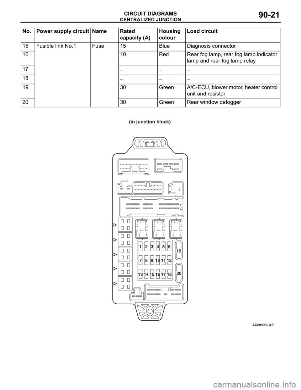
15Fusible link No.1Fuse15BlueDiagnosis connector
1610RedRear fog lamp, rear fog lamp indicator
lamp and rear fog lamp relay
17−−−
18−−−
1930GreenA/C-ECU, blower motor, heater control
unit and resistor
2030GreenRear window defogger
No. Power supply circuit Name Rated
capacity (A)Housing
colourLoad circuit
AC209082
(in junction block)
1234
56
7
89
20 19
10 11
12
131415
16
1718
AE