charging MITSUBISHI LANCER 2006 User Guide
[x] Cancel search | Manufacturer: MITSUBISHI, Model Year: 2006, Model line: LANCER, Model: MITSUBISHI LANCER 2006Pages: 800, PDF Size: 45.03 MB
Page 73 of 800
CHARGING SYSTEM
ENGINE ELECTRICAL16-11
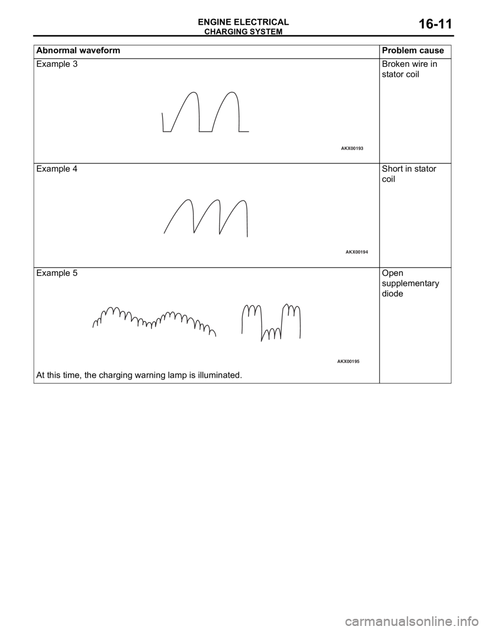
Example 3
AKX00193
Broken wire in
stator coil
Examp l e 4
AKX00194
Shor t in st ator
coil
Exampl e 5
AKX00195
At this time, the charg i ng warn ing lamp is illuminated .
Open
suppleme
n t a ry
d
i ode
Abn o rm al waveform P roble m caus e
Page 74 of 800
CHARGING SYSTEM
ENGINE ELECTRICAL16-12
ALTERNATOR ASSEMBLY
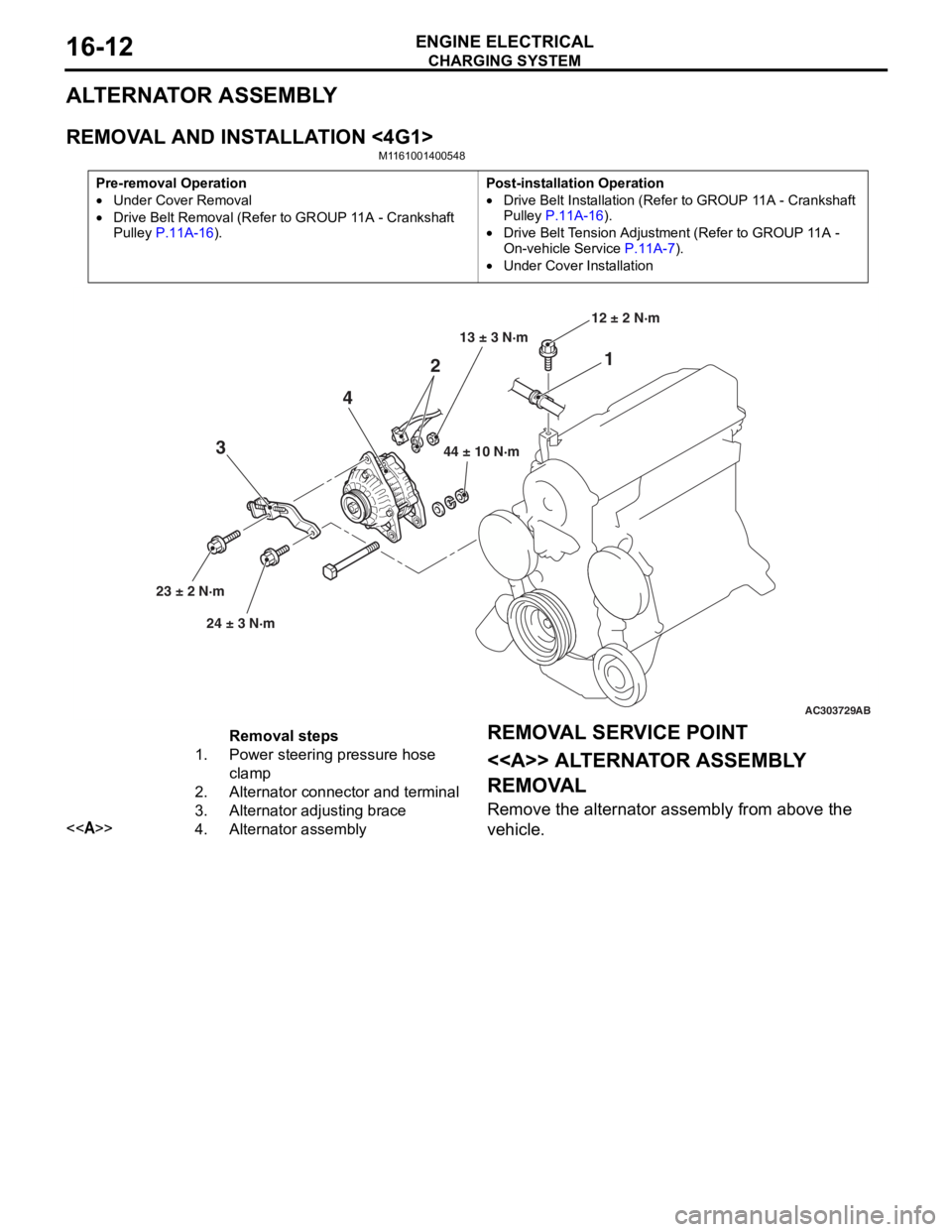
REMOVAL AND INSTALLATION <4G1>
M1161001400548
Pre-removal Operation
•Under Cover Removal
•Drive Belt Removal (Refer to GROUP 11A - Crankshaft
Pulley
P.11A-16).
Post-installation Operation
•Drive Belt Installation (Refer to GROUP 11A - Crankshaft
Pulley P.11A-16).
•Drive Belt Tension Adjustment (Refer to GROUP 11A -
On-vehicle Service P.11A-7).
•Under Cover Installation
AC303729
1
2
4
3
44 ± 10 N·m
23 ± 2 N·m 24 ± 3 N·m 12 ± 2 N·m
AB
13 ± 3 N·m
Removal steps
1.Power steering pressure hose
clamp
2.Alternator connector and terminal
3.Alternator adjusting brace
<>4.Alternator assembly
REMOV
A L SER VICE POINT
<> ALTERNA T O R ASSEMBL Y
REMOV
A L
Remove the a l tern ator assembly from above the
vehicle.
Page 75 of 800
CHARGING SYSTEM
ENGINE ELECTRICAL16-13
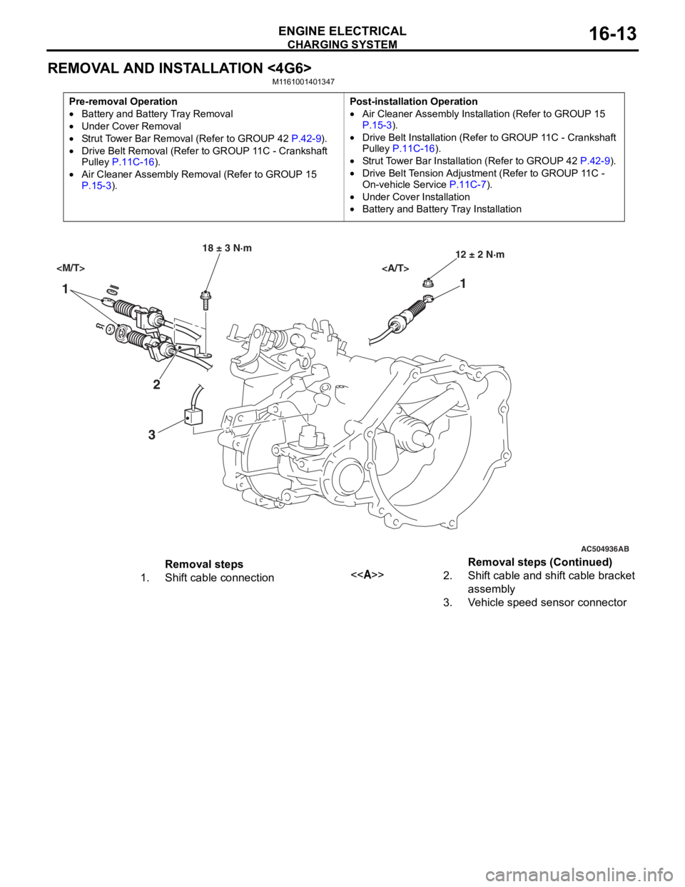
REMOVAL AND INSTALLATION <4G6>
M1161001401347
Pre-removal Operation
•Battery and Battery Tray Removal
•Under Cover Removal
•Strut Tower Bar Removal (Refer to GROUP 42 P.42-9).
•Drive Belt Removal (Refer to GROUP 11C - Crankshaft
Pulley P.11C-16).
•Air Cleaner Assembly Remo val (Refer to GROUP 15 P.15-3).
Post-installation Operation
•Air Cleaner Assembly Installation (Refer to GROUP 15 P.15-3).
•Drive Belt Installation (Refer to GROUP 11C - Crankshaft
Pulley P.11C-16).
•Strut Tower Bar Installation (Refer to GROUP 42 P.42-9).
•Drive Belt Tension Adjustment (Refer to GROUP 11C -
On-vehicle Service
P.11C-7).
•Under Cover Installation
•Battery and Battery Tray Installation
AC504936
1 1
2
3
18 ± 3 N·m 12 ± 2 N·m
AB
Removal steps
1.Shift cable connection<>2.Shift cable and shift cable bracket
assembly
3.Vehicle speed sensor connector
Removal steps (Continued)
Page 76 of 800
AC303827
65
84
9
7
22 ± 4 N·m
23 ± 3 N·m
8.8 ± 1.0 N·m 44 ± 10 N·m
AB
13 ± 3 N·m
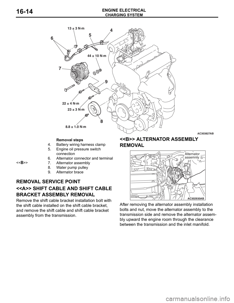
Removal steps
4.Battery wiring harness clamp
5.Engine oil pressure switch
connection
6.Alternator connector and terminal
<>7.Alternator assembly
8.Water pump pulley
9.Alternator brace
CHARGING SYSTEM
ENGINE ELECTRICAL16-14
REMOV
A L SER V ICE POINT
<> SHIFT CABLE AND SHIFT CABLE
BRACKET ASSEMBL
Y REMOV A L
Remove the shift cable bracket inst allation bolt with
the shif
t ca ble inst alled o n the shif t cable bracket,
and remove
the shif t cable and shif t cable bracket
assembly fro
m the transmission.
<> ALTERNA T O R ASSEMBL Y
REMOV
A L
AC302930 AB
Alternator
assemnly
Af
ter re moving the alternato r assembly inst allation
bolt
s a nd nu t, move the alte rnator a sse mbly to the
transmission side an
d remove the alternato r assem
-
bly upward the engine roo m thr ough th e clearan ce
between t
he tran smission and the inlet ma nifold.
Page 77 of 800
CHARGING SYSTEM
ENGINE ELECTRICAL16-15
DISASSEMBLY AND REASSEMBLY
M1161001600166
AK202845
1
2 3
4
5
6
7
8 9
10
11
12
1314
AE
4.4 ± 1.0 N·m
3.7 ± 0.7 N·m
189 ± 19 N·m
3.7 ± 0.7 N·m
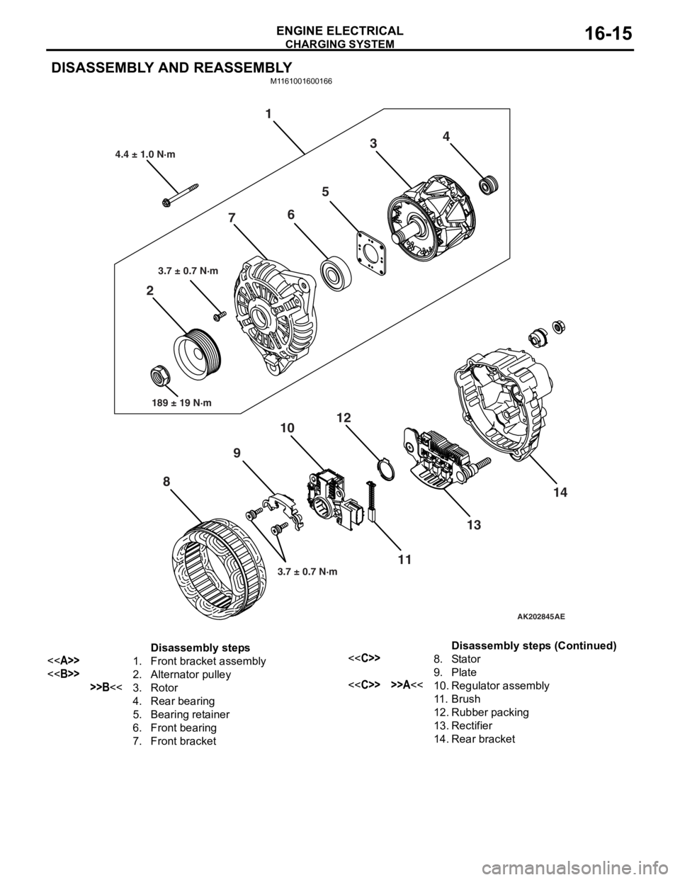
Disassembly steps
<>1.Front bracket assembly
<>2.Alternator pulley
>>B<<3.Rotor
4.Rear bearing
5.Bearing retainer
6.Front bearing
7.Front bracket
<
9.Plate
<
11 .Brush
12.Rubber packing
13.Rectifier
14.Rear bracket
Disassembly steps (Continued)
Page 78 of 800
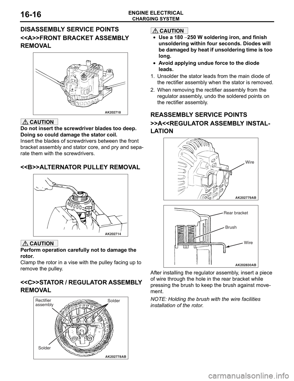
Page 79 of 800
CHARGING SYSTEM
ENGINE ELECTRICAL16-17
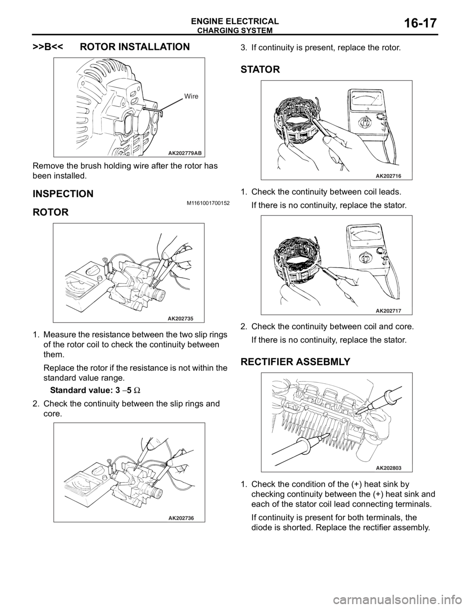
>>B<< ROTOR INSTALLATION
AK202779
Wire
AB
Remove the br ush holding wire af ter the rotor ha s
been inst
alled.
INSPECTION
M1161 0017 0015 2
ROTO R
AK202735
1. Measure th e resist a n ce b e tween the two slip rings
of the rot o r coil to check t he co ntinu i ty between
th em.
Repla c e th e r o to r if th e resist ance is no t within the
st
a ndard valu e range .
St andard va lue: 3 − 5 Ω
2.Check t he co ntinu i ty between the slip rings and
core.
AK202736
3. If cont inuity is pre s ent, repla c e th e rotor .
STA T OR
AK202716
1.Check t he co ntinu i ty between coil le ads.
If there is no con t inuity , replace the st a t or .
AK202717
2.Check t he co ntinu i ty between coil and core .
If there is no con t inuity , replace the st a t or .
RECTIFIER ASSEBMLY
AK202803
1.Check t he co ndition o f the (+) h eat sink by
checkin g contin uity be twe en t he (+) heat sink and
e a ch o f the st a t or coil lead conn ecting termina l s.
If cont inuity is pre s ent for both terminals, the
d
i ode is shorte d. Repla c e th e rectifie r assembly .
Page 80 of 800
AK202802
CHARGING SYSTEM
ENGINE ELECTRICAL16-18
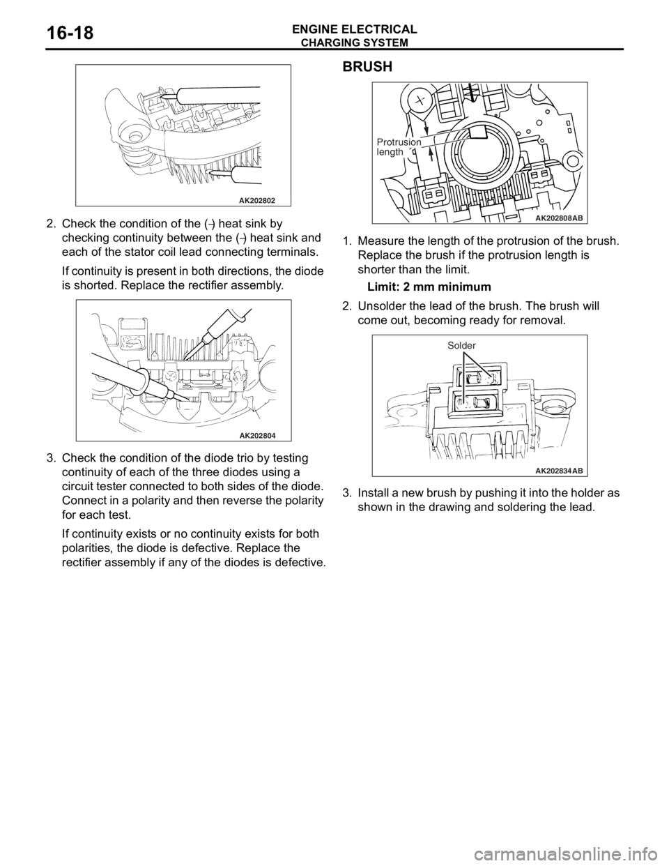
2.Check t he co ndition of the (−) heat sink by
checkin
g
con
t
inuity b
e
tween th e (
−) he at sink and
ea
ch o
f
the st
a
t
or co
il lead conne
cting termina l s.
If con t inu i ty is p r ese n t in bot h d i re ctio ns, the dio de
is shorted.
Re place the rectifier assembly .
AK202804
3.Check t he co ndition of the diode t r io by testing
continuity of ea ch o f the th ree diodes using a
circuit tester con necte d to both sides of the dio de.
Co nnect in a p o la rity a nd then reverse the polarity
fo r each test.
If continuity exist s or no cont inuity exist s for bo th
po
larities, the d i ode is d e fective . Repla c e th e
rectifier assembly if a
n y o f the d i odes is defe c tive.
BRUSH
AK202808
Protrusion
length
AB
1.Measure the lengt h of the prot rusion o f the bru s h.
Replace the b r ush if the protrusion lengt h is
shorter than th e limit .
Limit: 2 mm mini mum
2.Unsolde r the lead o f the br ush. The bru s h will
come out, b e coming ready for removal.
AK202834
Solder
AB
3.I n st all a ne w b r ush b y pu sh in g it int o the h o lde r a s
shown in the d r awing a nd soldering th e lea d .
Page 465 of 800
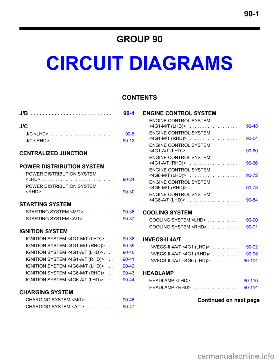
90-1
GROUP 90
CIRCUIT DIAGRAMS
CONTENTS
J/B . . . . . . . . . . . . . . . . . . . . . . . . . . .90-4
J/C
J/C
J/C
CENTRALIZED JUNCTION
POWER DISTRIBUTION SYSTEM
POWER DISTRIBUTION SYSTEM
POWER DISTRIBUTION SYSTEM
STARTING SYSTEM
STARTING SYSTEM
STARTING SYSTEM . . . . . . . . . . . . 90-37
IGNITION SYSTEM
IGNITION SYSTEM <4 G1-M/T (LHD)> . . . 90-38
IGNITION SYSTEM <4G1-M/T (RHD)> . . . 90-39
IGNITION SYSTEM <4G1-A/T (LHD)> . . . . 90-40
IGNITION SYSTEM <4G1-A/T (RHD)> . . . 90-41
IGNITION SYSTEM <4G6-M/T (LHD)> . . . 90-42
IGNITION SYSTEM <4G6-M/T (RHD)> . . . 90-43
IGNITION SYSTEM <4G6-A/T (LHD)> . . . . 90-44
CHARGING SYSTEM
CHARGING SYSTEM
CHARGING SYSTEM . . . . . . . . . . . 90-47
ENGINE CONTROL SYSTEM
ENGINE CONTROL SYSTEM
<4G1-M/T (LHD)> . . . . . . . . . . . . . . . . . . . . 90-48
ENGINE CONTROL SYSTEM
<4G1-M/T (RHD)> . . . . . . . . . . . . . . . . . . . . 90-54
ENGINE CONTROL SYSTEM
<4G1-A/T (LHD)> . . . . . . . . . . . . . . . . . . . . 90-60
ENGINE CONTROL SYSTEM
<4G1-A/T (RHD)> . . . . . . . . . . . . . . . . . . . . 90-66
ENGINE CONTROL SYSTEM
<4G6-M/T (LHD)> . . . . . . . . . . . . . . . . . . . . 90-72
ENGINE CONTROL SYSTEM
<4G6-M/T (RHD)> . . . . . . . . . . . . . . . . . . . . 90-78
ENGINE CONTROL SYSTEM
<4G6-A/T (LHD)> . . . . . . . . . . . . . . . . . . . . 90-84
COOLING SYSTEM
COOLING SYSTEM
COOLING SYSTEM
INVECS-II 4A/T
INVECS-II 4A/T <4G1 (LHD)> . . . . . . . . . . . 90-92
INVECS-II 4A/T <4G1 (RHD)> . . . . . . . . . . 90-98
INVECS-II 4A/T <4G6 (LHD)> . . . . . . . . . . . 90-104
HEADLAMP
HEADLAMP
HEADLAMP
Continued on next page
Page 474 of 800
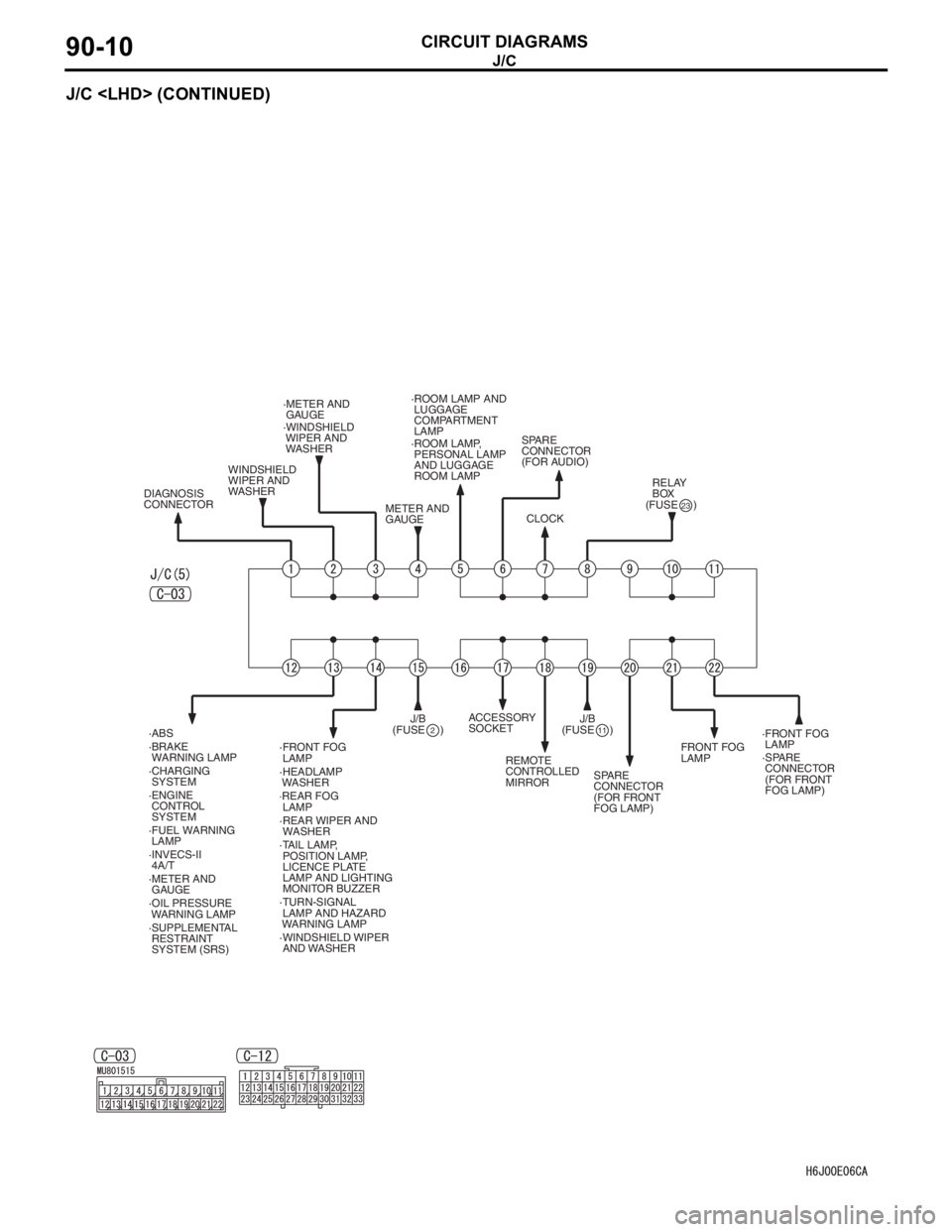
J/C
CIRCUIT DIAGRAMS90-10
J/C
·FRONT FOG
LAMP ·FRONT FOG
LAMP
FRONT FOG
LAMP
·TURN-SIGNAL
LAMP AND HAZARD
WARNING LAMP ·HEADLAMP
WASHER ·ROOM LAMP AND
LUGGAGE
COMPARTMENT
LAMP
·ROOM LAMP,
PERSONAL LAMP
AND LUGGAGE
ROOM LAMP
·TAIL LAMP,
POSITION LAMP,
LICENCE PLATE
LAMP AND LIGHTING
MONITOR BUZZER
·WINDSHIELD WIPER
AND WASHER·WINDSHIELD
WIPER AND
WASHER
WINDSHIELD
WIPER AND
WASHER
DIAGNOSIS
CONNECTOR·METER AND
GAUGE
·METER AND
GAUGE METER AND
GAUGESPARE
CONNECTOR
(FOR AUDIO)
SPARE
CONNECTOR
(FOR FRONT
FOG LAMP)·SPARE
CONNECTOR
(FOR FRONT
FOG LAMP) CLOCK(FUSE )
23
(FUSE )2
RELAY
BOX
·REAR FOG
LAMP
·REAR WIPER AND
WASHER ·ABS
·BRAKE
WARNING LAMP
·CHARGING
SYSTEM
·ENGINE
CONTROL
SYSTEM
·FUEL WARNING
LAMP
·INVECS-II
4A/T
·SUPPLEMENTAL
RESTRAINT
SYSTEM (SRS) ·OIL PRESSURE
WARNING LAMP J/B
(FUSE )
11J/B ACCESSORY
SOCKET
REMOTE
CONTROLLED
MIRROR