radiator MITSUBISHI LANCER 2006 User Guide
[x] Cancel search | Manufacturer: MITSUBISHI, Model Year: 2006, Model line: LANCER, Model: MITSUBISHI LANCER 2006Pages: 800, PDF Size: 45.03 MB
Page 47 of 800
RADIATOR
ENGINE COOLING14-33
RADIATOR
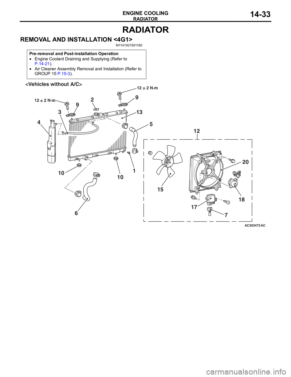
REMOVAL AND INSTALLATION <4G1>M1141001501160
Pre-removal and Post-installation Operation
•Engine Coolant Draining and Supplying (Refer to
P.14-21).
•Air Cleaner Assembly Removal and Installation (Refer to
GROUP 15
P.15-3).
AC303472
18
17
15 20
12
9
13 5
2
9
3
4
1
10
6
10
AC
12 ± 2 N·m
12 ± 2 N·m
7
Page 48 of 800
AC303473
18
17 15
20
12
9
13
5
2
9
3
4
1
10
6
10
12 ± 2 N·m
AC
12 ± 2 N·m
16
19
8
11
7
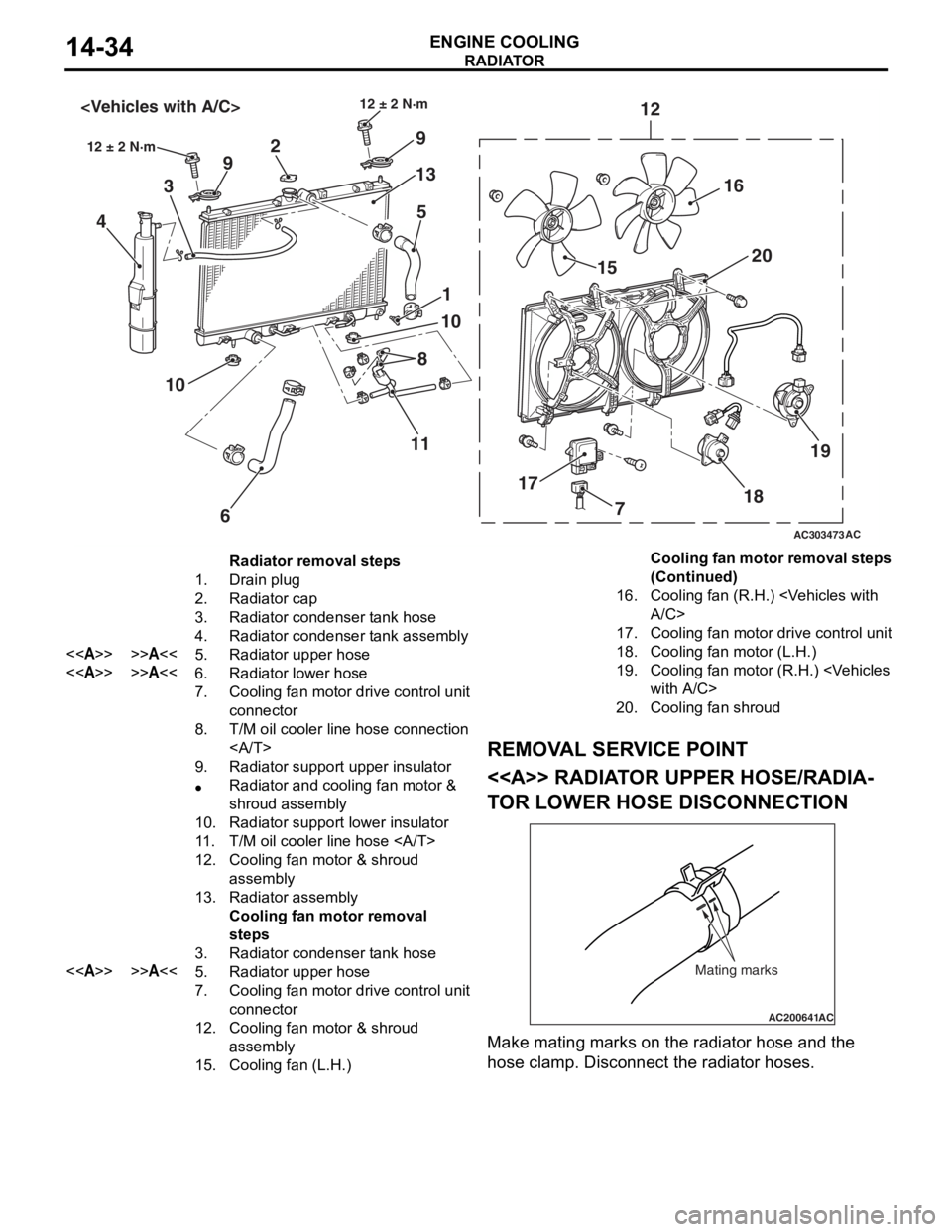
Radiator removal steps
1.Drain plug
2.Radiator cap
3.Radiator condenser tank hose
4.Radiator condenser tank assembly
<>>>A<<5.Radiator upper hose
<>>>A<<6.Radiator lower hose
7.Cooling fan motor drive control unit
connector
8.T/M oil cooler line hose connection
9.Radiator support upper insulator
•Radiator and cooling fan motor &
shroud assembly
10.Radiator support lower insulator
11 .T/M oil cooler line hose
12.Cooling fan motor & shroud
assembly
13.Radiator assembly
Cooling fan motor removal
steps
3.Radiator condenser tank hose
<>>>A<<5.Radiator upper hose
7.Cooling fan motor drive control unit
connector
12.Cooling fan motor & shroud
assembly
15.Cooling fan (L.H.)
16.Cooling fan (R.H.)
17.Cooling fan motor drive control unit
18.Cooling fan motor (L.H.)
19.Cooling fan motor (R.H.)
20.Cooling fan shroud
RADIA T OR
ENGINE COOLING14-34
REMOV A L SER VICE POINT
<> RADIAT OR UPPER HOSE/RADIA-
TO R LOW E R HOSE DISCONNECTION
AC200641AC
Mating marks
Make mating marks on the rad i ator hose and th e
hose
cla m p. Disconnect the ra diat or hoses.
Cooling fan motor removal steps
(Continued)
Page 49 of 800
RADIATOR
ENGINE COOLING14-35
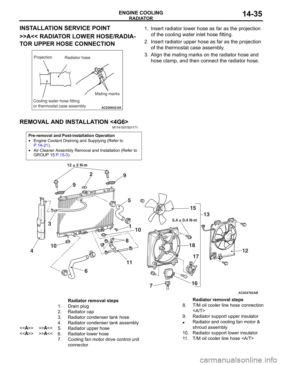
INSTALLATION SERVICE POINT
>>A<< RADIATOR LOWER HOSE/RADIA-
TOR UPPER HOSE CONNECTION
AC200642
Mating marks
Projection
Cooling water hose fitting
or thermostat case assembly
AK
Radiator hose
1.In sert ra diato r lower h o se as fa r as th e projection
o f the cooling wate r inlet hose fit t ing.
2.In sert radia t or up per h o se as far a s t he pro j ection
o f the th ermost at ca se asse mbly .
3.Align th e ma ting marks on the rad i ator hose and
h o se clamp, an d then conn ect the radiator h o se.
REMOVA L AND INST ALLA TION <4G6>
M11 4100 1501 17 1
Pre-removal and Post-installation Operation
•Engine Coolant Draining and Supplying (Refer to
P.14-21).
•Air Cleaner Assembly Removal and Installation (Refer to
GROUP 15
P.15-3).
AC504783
1
12 ± 2 N·m
10
2
3
4
5
6
7
8
9
9
10
11 13
15
18
16
17
12
AB
5.4 ± 0.4 N·m
Radiator removal steps
1.Drain plug
2.Radiator cap
3.Radiator condenser tank hose
4.Radiator condenser tank assembly
<>>>A<<5.Radiator upper hose
<>>>A<<6.Radiator lower hose
7.Cooling fan motor drive control unit
connector
8.T/M oil cooler line hose connection
9.Radiator support upper insulator
•Radiator and cooling fan motor &
shroud assembly
10.Radiator support lower insulator
11 .T/M oil cooler line hose
Radiator removal steps
Page 50 of 800
RADIATOR
ENGINE COOLING14-36
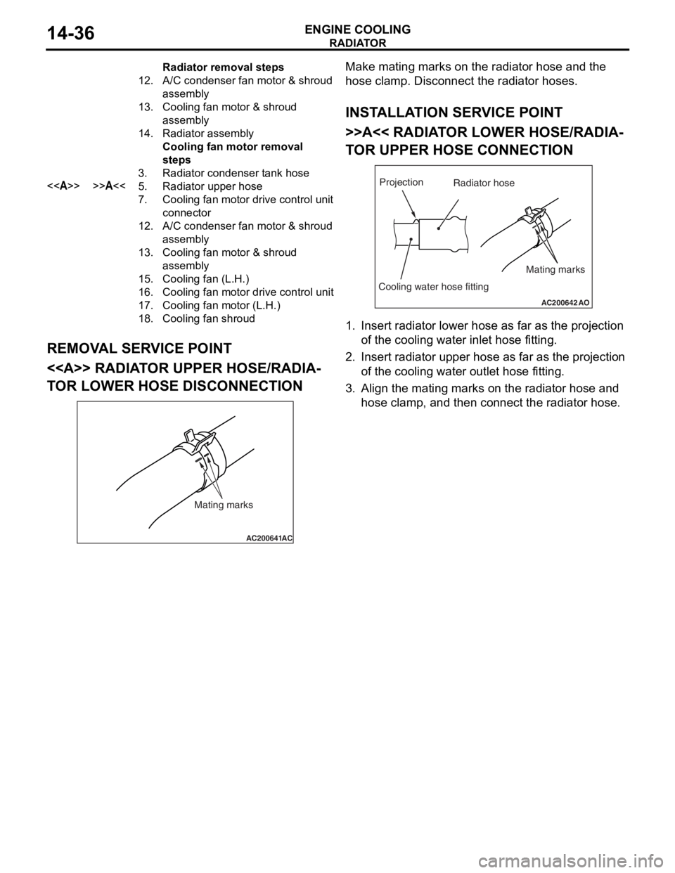
REMOVAL SERVICE POINT
<> RADIATOR UPPER HOSE/RADIA-
TOR LOWER HOSE DISCONNECTION
AC200641AC
Mating marks
Make mating marks on the rad i ator hose and th e
hose
cla m p. Disconnect the ra diat or hoses.
INSTALLA T ION SER VICE POINT
>>A<< RADIAT OR LOW E R HOSE/RADIA-
TO R UPPER HOSE CONNECTION
AC200642
Mating marks
Projection
Cooling water hose fitting
AO
Radiator hose
1.In sert ra diato r lower h o se as fa r as th e projection
o f the cooling wate r inlet hose fit t ing.
2.In sert radia t or up per h o se as far a s t he pro j ection
o f the cooling wate r outle t hose fitt ing.
3.Align th e ma ting marks on the rad i ator hose and
h o se clamp, an d then conn ect the radiator h o se.
12.A/C con den se r fan mo to r & sh ro ud
assembly
13.Coo ling fan mo to r & sh ro ud
assembly
14.Rad i ator a s sem b ly
Cooling fan mo tor r e mova l
st
ep s
3.Radi ator con den ser t a nk h o se
<>>>A<<5.Radi ator u ppe r ho se
7.Cooling fan mo to r dr ive contr o l unit
con
nector
12.A/C con den se r fan mo to r & sh ro ud
assembly
13.Coo ling fan mo to r & sh ro ud
assembly
15.Coo ling fan ( L .H.)
16.Coo ling fan mo to r dr ive contro l unit
17.Coo ling fan mo to r ( L .H.)
18.Coo ling fan shr o u d
Radiator re mova l st ep s
Page 335 of 800
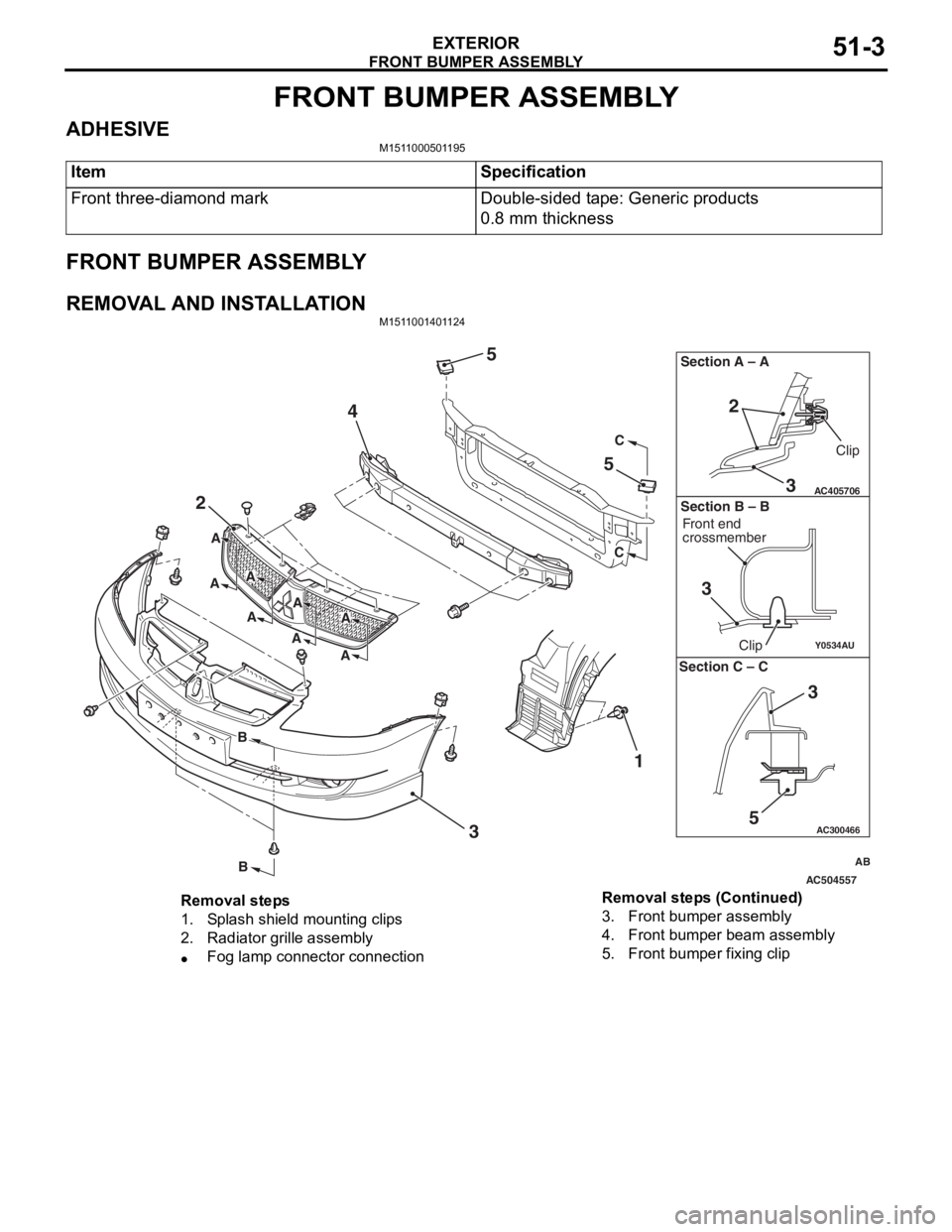
FRONT BUMPER ASSEMBLY
EXTERIOR51-3
FRONT BUMPER ASSEMBLY
ADHESIVEM1511000501195
ItemSpecification
Front three-diamond markDouble-sided tape: Generic products
0.8 mm thickness
FRONT BUMPER ASSEMBLY
REMOVAL AND INSTALLATIONM1511001401124
AC504557
AC300466
Y0534AU
AC405706
AB
2
4
5
5
3 1
C
C
B
B
A
A
A
AA
A
A
A
3
2
Section A – A
3
Clip
Front end
crossmember
Clip
Section B – B
5
3
Section C – C
Removal steps
1.Splash shield mounting clips
2.Radiator grille assembly
•Fog lamp connector connection
3.Front bumper assembly
4.Front bumper beam assembly
5.Front bumper fixing clip
Removal steps (Continued)
Page 336 of 800
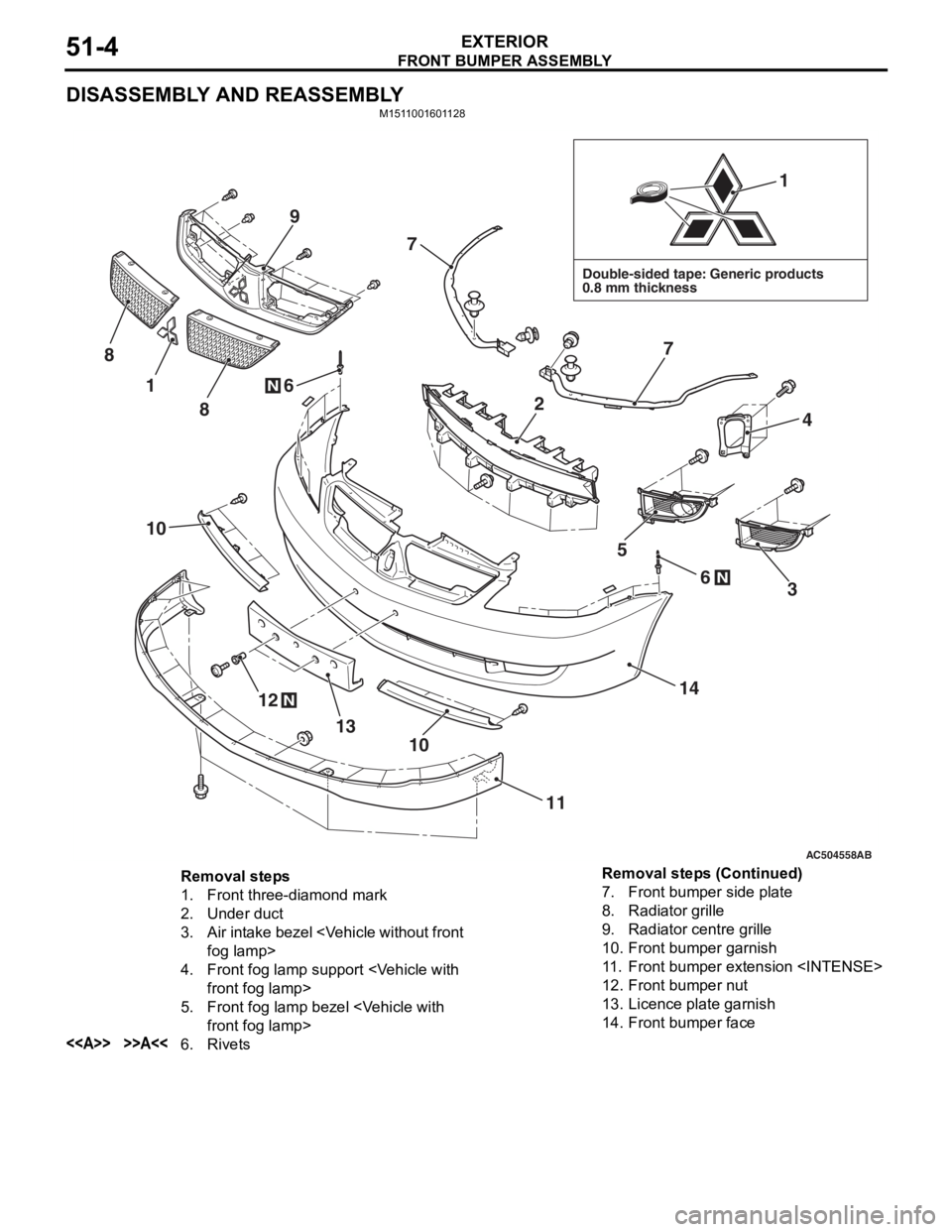
FRONT BUMPER ASSEMBLY
EXTERIOR51-4
DISASSEMBLY AND REASSEMBLY
M1511001601128
AC504558AB
Double-sided tape: Generic products
0.8 mm thickness
1
1
12
13
14
11
10
10
4
7
7
6
6
8
9
8
5
3N
N
N
2
Removal steps
1.Front three-diamond mark
2.Under duct
3.Air intake bezel
4.Front fog lamp sup port
5.Front fog lamp bezel
<>>>A<<6.Rivets
7.Front bumper side plate
8.Radiator grille
9.Radiator centre grille
10.Front bumper garnish
11 .Front bumper extension
12.Front bumper nut
13.Licence plate garnish
14.Front bumper face
Removal steps (Continued)
Page 393 of 800
AC304537
JK*
AE
ECU
COMPONENT LOCA TIONS70-3
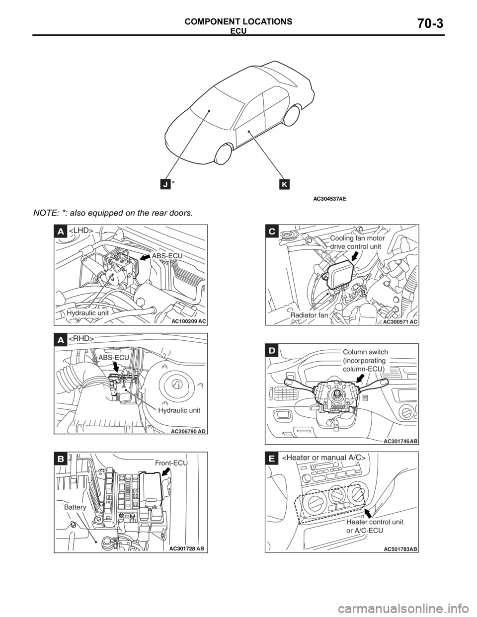
NOTE: *: also eq uipp ed on the rear doors.
AC100209AC
A
ABS-ECU
Hydraulic unit
AC206790
A
AD
ABS-ECU
Hydraulic unit
AC301728AB
BFront-ECU
Battery
AC300571
C
ACRadiator fan
Cooling fan motor
drive control unit
AC301746
DColumn switch
(incorporating
column-ECU)
AB
AC501783AB
E
Heater control unit
or A/C-ECU
Page 395 of 800
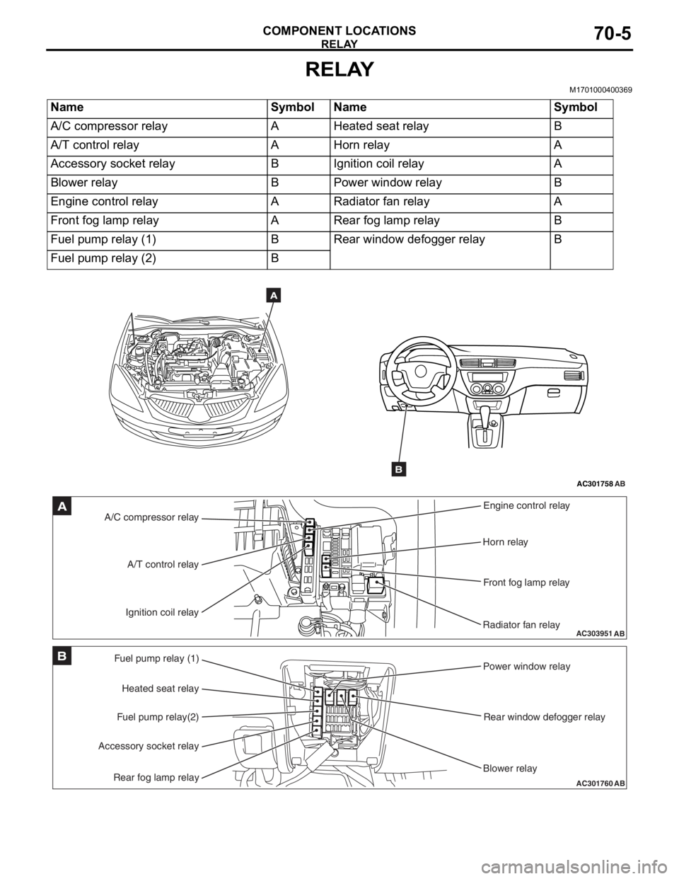
RELAY
COMPONENT LOCATIONS70-5
RELAY
M1701000400369
NameSymbolNameSymbol
A/C compressor relayAHeated seat relayB
A/T control relayAHorn relayA
Accessory socket relayBIgnition coil relayA
Blower relayBPower window relayB
Engine control relayARadiator fan relayA
Front fog lamp relayARear fog lamp relayB
Fuel pump relay (1)BRear window defogger relayB
Fuel pump relay (2)B
AC301758AB
A
B
AC303951AB
A/C compressor relayEngine control relay
Horn relay
Front fog lamp relay
Radiator fan relay
A/T control relay
Ignition coil relayA
AC301760
Fuel pump relay (1) Power window relay
Rear window defogger relay
Blower relay
Heated seat relay
Fuel pump relay(2)
Accessory socket relay
Rear fog lamp relayAB
B
Page 554 of 800
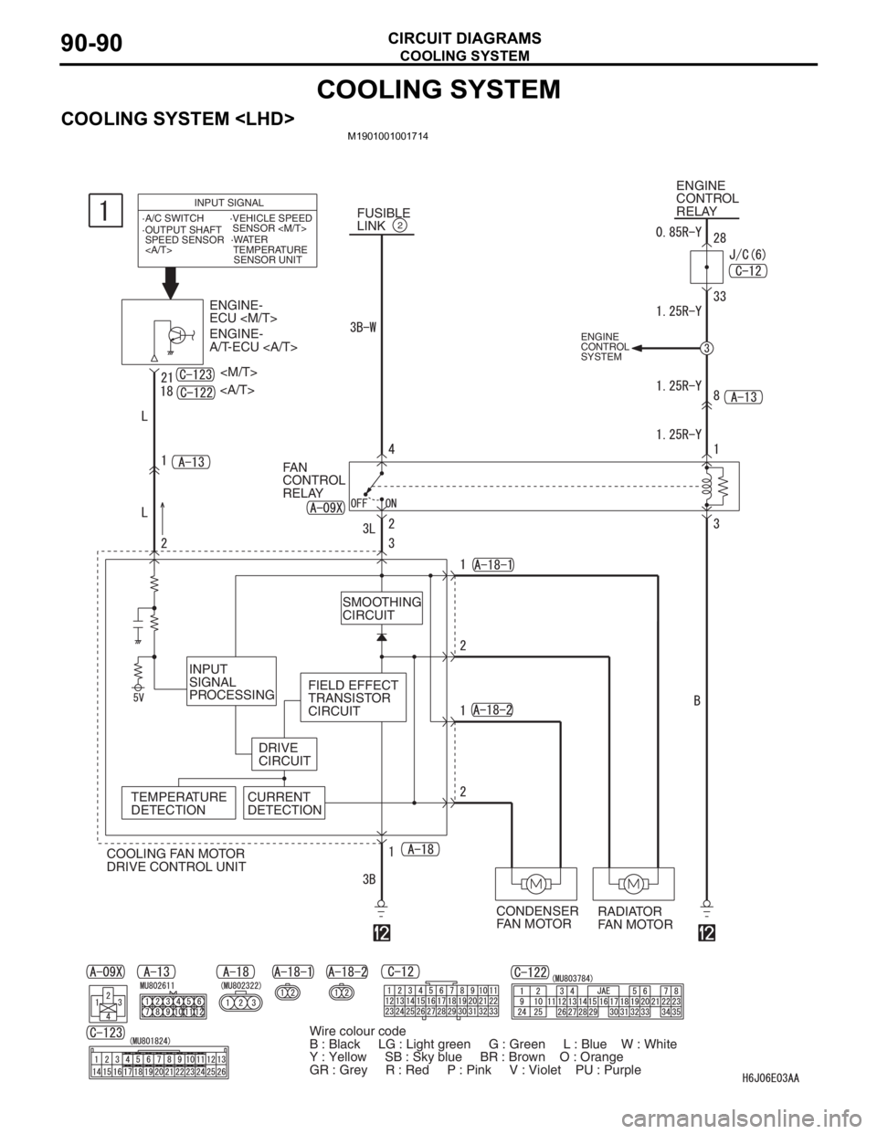
COOLING SYSTEM
CIRCUIT DIAGRAMS90-90
COOLING SYSTEM
COOLING SYSTEM
FUSIBLE
LINK2
ENGINE
CONTROL
RELAY
ENGINE-
ECU
ENGINE-
A/T-ECU
FAN
CONTROL
RELAY
RADIATOR
FAN MOTOR CONDENSER
FAN MOTOR COOLING FAN MOTOR
DRIVE CONTROL UNIT
INPUT SIGNAL
·A/C SWITCH
·WATER
TEMPERATURE
SENSOR UNIT ·OUTPUT SHAFT
SPEED SENSOR
·VEHICLE SPEED
SENSOR
SMOOTHING
CIRCUIT
INPUT
SIGNAL
PROCESSING
DRIVE
CIRCUITFIELD EFFECT
TRANSISTOR
CIRCUIT
TEMPERATURE
DETECTIONCURRENT
DETECTION
ENGINE
CONTROL
SYSTEM
Wire colour code
B : Black LG : Light green G : Green L : Blue W : White
Y : Yellow SB : Sky blue BR : Brown O : Orange
GR : Grey R : Red P : Pink V : Violet PU : Purple
Page 555 of 800
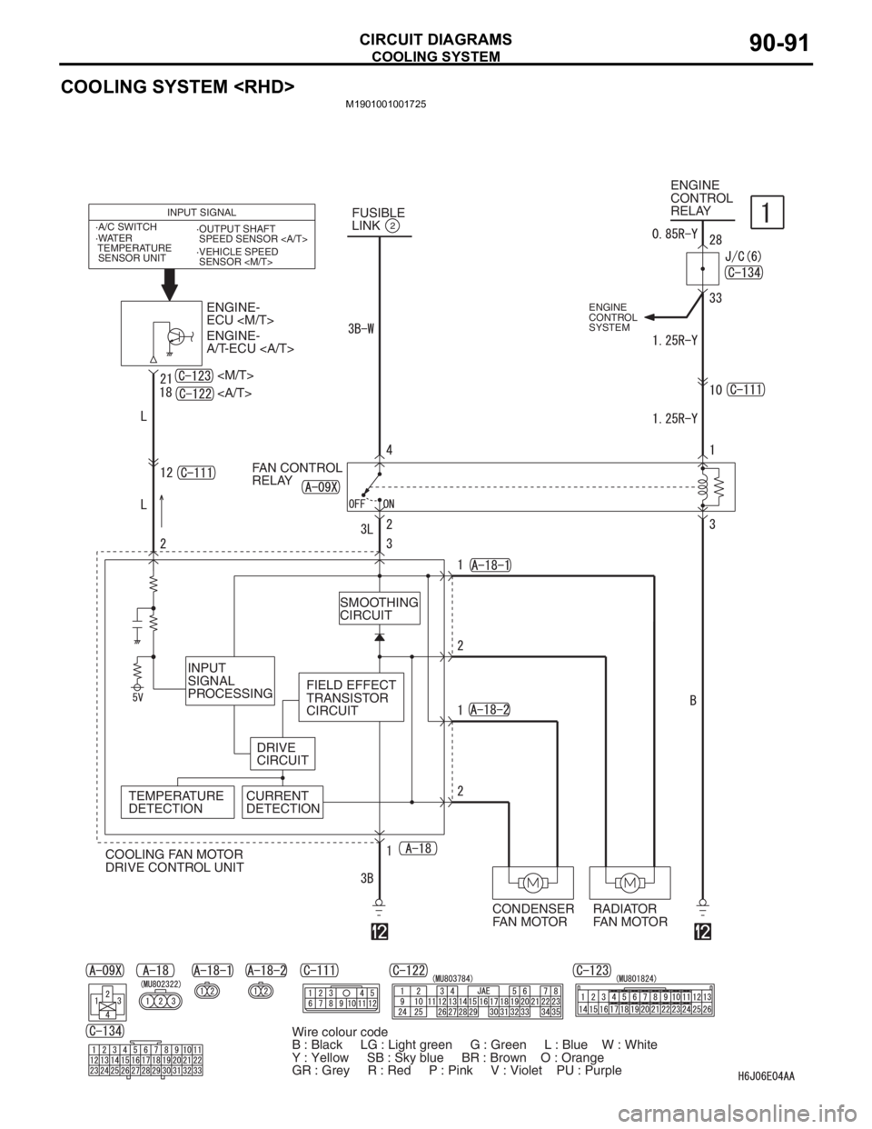
COOLING SYSTEM
CIRCUIT DIAGRAMS90-91
COOLING SYSTEM
M1901001001725
Wire colour code
B : Black LG : Light green G : Green L : Blue W : White
Y : Yellow SB : Sky blue BR : Brown O : Orange
GR : Grey R : Red P : Pink V : Violet PU : PurpleFUSIBLE
LINK
2
ENGINE
CONTROL
RELAY
ENGINE-
ECU
ENGINE-
A/T-ECU
FAN CONTROL
RELAY
RADIATOR
FAN MOTOR CONDENSER
FAN MOTOR COOLING FAN MOTOR
DRIVE CONTROL UNIT
INPUT SIGNAL
·A/C SWITCH
·WATER
TEMPERATURE
SENSOR UNIT·OUTPUT SHAFT
SPEED SENSOR
·VEHICLE SPEED
SENSOR
SMOOTHING
CIRCUIT
INPUT
SIGNAL
PROCESSING
DRIVE
CIRCUIT
TEMPERATURE
DETECTIONCURRENT
DETECTION
ENGINE
CONTROL
SYSTEM
FIELD EFFECT
TRANSISTOR
CIRCUIT