tow MITSUBISHI LANCER 2006 User Guide
[x] Cancel search | Manufacturer: MITSUBISHI, Model Year: 2006, Model line: LANCER, Model: MITSUBISHI LANCER 2006Pages: 800, PDF Size: 45.03 MB
Page 213 of 800
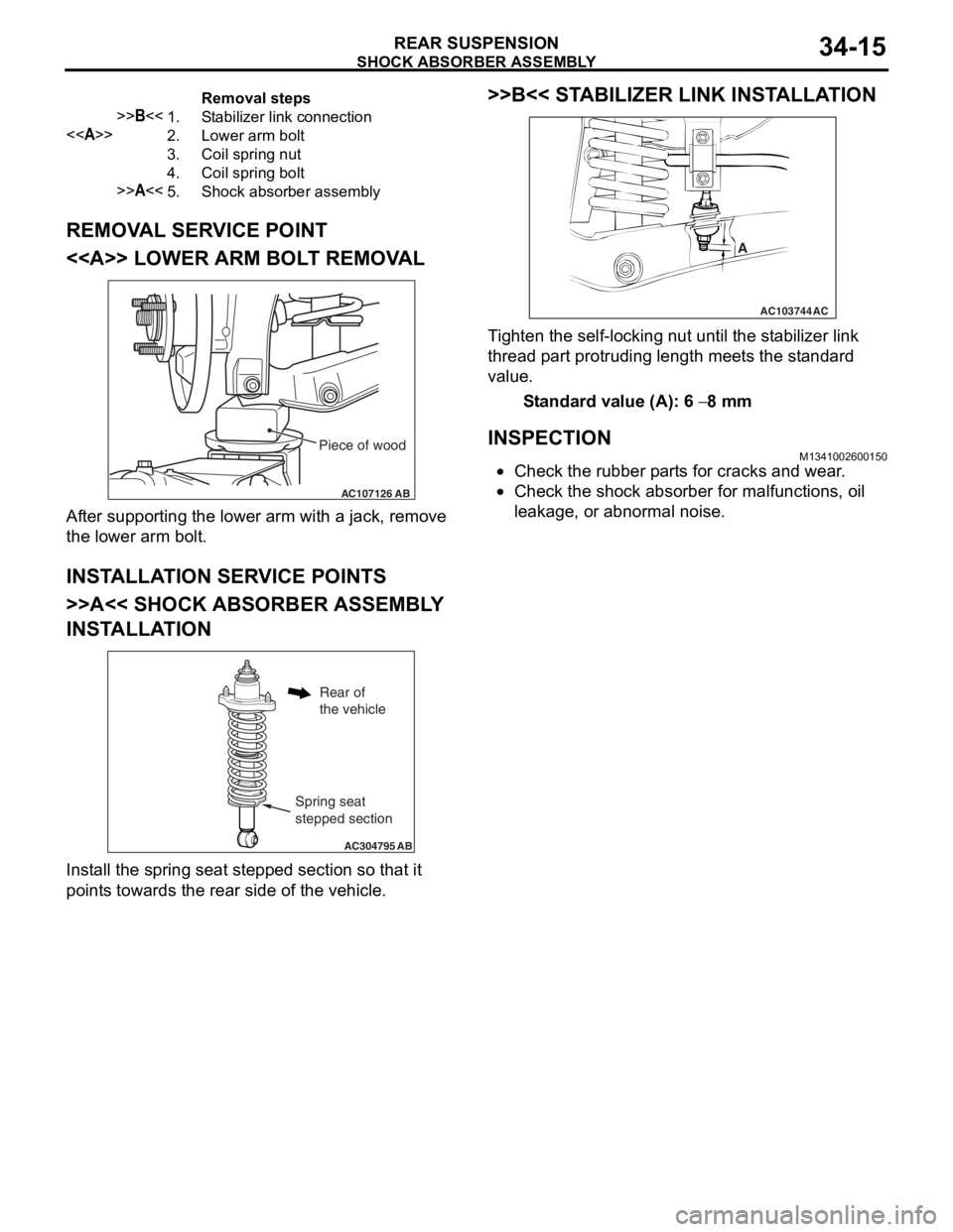
Removal steps
>>B<<1.Stabilizer link connection
<>2.Lower arm bolt
3.Coil spring nut
4.Coil spring bolt
>>A<<5.Shock absorber assembly
SHOCK ABSORBER ASSEMBLY
REAR SUSPENSION34-15
REMOVAL SERVICE POINT
<> LOWER ARM BOLT REMOVAL
AC107126AB
Piece of wood
After suppo rting the lo we r arm with a jack, remove
the lo
we r arm b o lt.
INSTALLA T ION SER VICE POINT S
>>A<< SHOCK ABSORBER ASSEMBL Y
INST
ALLA TION
AC304795 AB
Spring seat
stepped section
Rear of
the vehicle
Install the sprin g se at ste pped section so th at it
point
s towards the rea r side of th e ve hicle.
>>B<< STABILIZER LINK INST ALLA TION
AC103744
A
AC
Ti ghten the self-locking nut un til t he st ab ilizer link
thread
p a rt protrud i ng length mee t s the st a ndard
value.
St andard va lue (A): 6 − 8 mm
INSPECTIONM13410026 0015 0
•Check the rubbe r p a rt s for cracks a nd wear .
•Check the sho c k abso r ber for malfunct i ons, oil
le
akag e, or a bnormal no ise .
Page 228 of 800
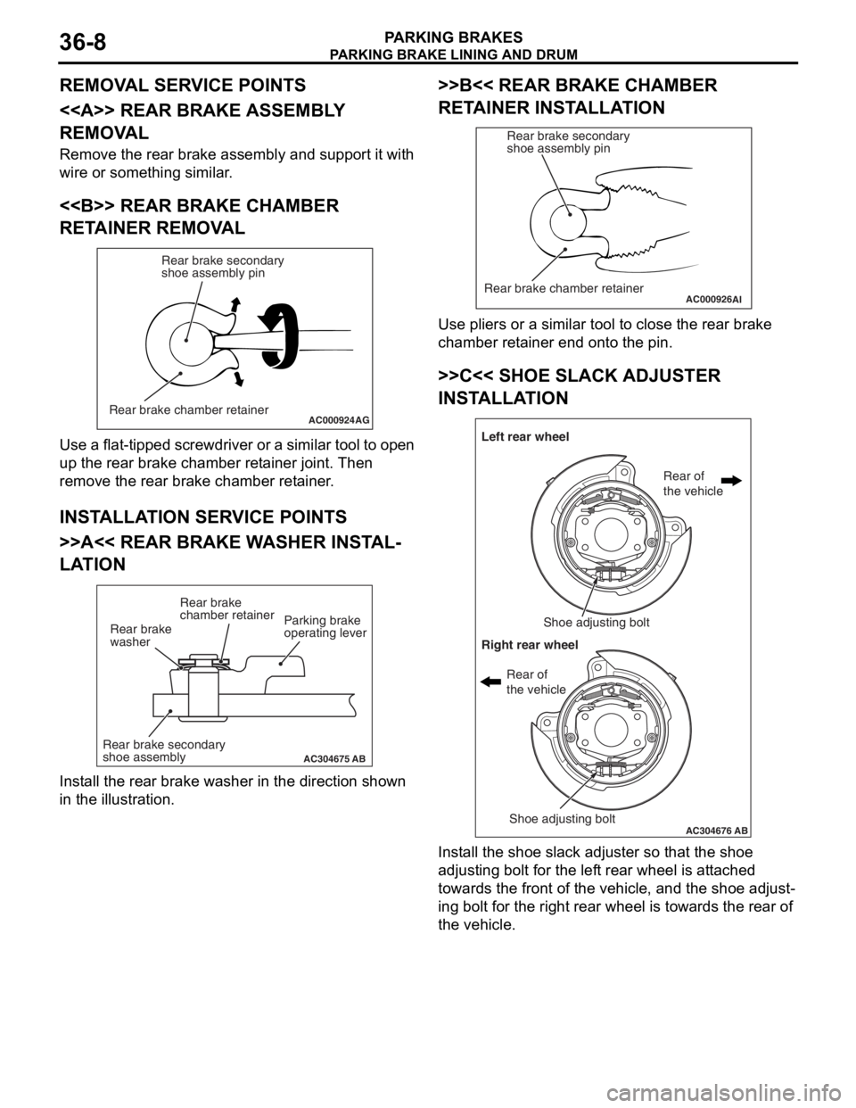
Page 241 of 800
ON-VEHICLE SERVICE
POWER STEERING37-11
ON-VEHICLE SERVICE
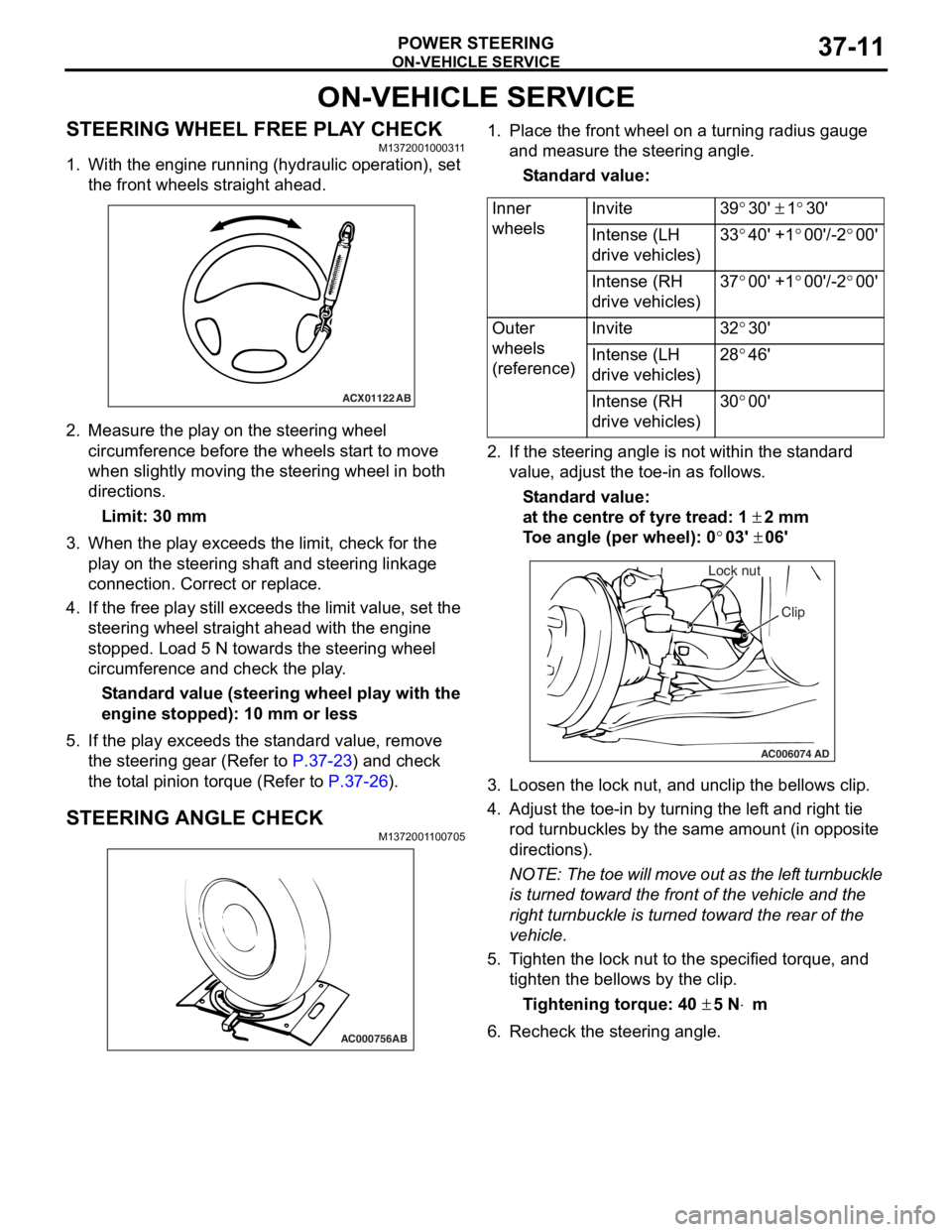
STEERING WHEEL FREE PLAY CHECKM1372001000311
1. With the engine running (hydraulic operation), set the front wheels straight ahead.
ACX01122 AB
2.Measure the play on th e ste e ring wh eel
circumfer ence before the whee ls st a r t to move
when slightly moving the stee ring whe e l in both
direct ions.
Limit: 30 mm
3.Wh en the play exceed s the limit, check fo r the
play on the stee ring shaf t and stee ring linkage
connectio n . Correct or replace .
4.If th e free play still exceeds the limit valu e, set t he
steering wheel stra ight ahead with the engine
stoppe d. Loa d 5 N towards the steer ing whee l
circumfer ence and check the play .
St andard value (steering whee l pla y with the
engine s
t opped): 1 0 mm o r l ess
5.If the play e xce eds the st an dard value , remove
th e ste e ring gear (Refe r to
P.37-23) and check
the tot a l p i nion torqu e (Refer to P.37-26).
STEERING ANGLE CHECKM137200 1 1 0070 5
AC000756AB
1.Place t he fron t wh eel on a tu rning radiu s gau ge
a nd me asure the steering ang le.
St andard va lue:
Inner
wheelsInvite39°30' ± 1°30'
Intense (LH
drive vehicles)33°40' +1°00'/-2°00'
Intense (RH
drive vehicles)37°00' +1°00'/-2°00'
Outer
wheels
(reference)Invite32°30'
Intense (LH
drive vehicles)28°46'
Intense (RH
drive vehicles)30°00'
2.If the steerin g ang le is not within the st a ndard
value , adjust t he toe-in as follows.
St andard va lue:
at the centre of tyre trea d: 1 ± 2 mm
To e angle (p er whee l): 0°03' ± 06'
AC006074 AD
Lock nut
Clip
3.L oose n the lock nut, and un clip the bellows clip .
4.Adjust the toe - in by turning th e lef t an d righ t tie
ro d turnb u ckles by th e sa me a m oun t (in o pposite
directions).
NOTE: The to e will move out as th e lef t turnbuckle
is tur
ned toward the fro n t of th e ve hicle an d the
right tu
rnbuckle is turned toward the rear of the
vehicle.
5. T i ghten the lo ck nut to the specified torque , and
tighten the be llo ws by the clip .
Ti ghte n ing torque: 40 ± 5 N⋅m
6.Recheck the stee ring a ngle .
Page 251 of 800
AC210969AD
Clip
Steering column
shaft
STE E RING C O LUMN SHAFT AS SEMBL Y
POWER STEERING37-21
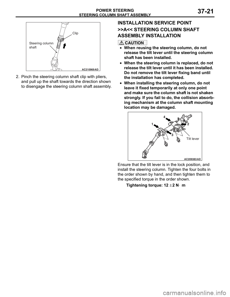
2.Pin c h t he st eering column shaf t clip with pliers,
an d pull up the shaf t towards the d i rection shown
to disengag e the steering column shaf t assembly .
INSTALLA T ION SER VICE POINT
>>A<< STEERING COLUMN SHAFT
ASSEMBL
Y INST ALLA TION
CAUTION
•When reusing the steering column, do not
release the tilt lever until the steering column
shaft has been installed.
•When the steering column is replaced, do not
release the tilt lever until it has been installed.
Do not remove the tilt lever fixing band until
the installation has completed.
•When installing the steering column, do not
leave it fixed temporarily at only one point
and make sure the column shaft is not shaken
strongly. If you fail to do, the collision absorb
-
ing mechanism at the column shaft mounting
location may be damaged.
AC209383AD
14
3 2
Tilt lever
Ensure that the tilt lever is in the lock position, and
install the steering column. Tighten the four bolts in
the order shown by hand, and then tighten them to
the specified torque in the order shown.
Tightening torque: 12 ± 2 N⋅m
Page 263 of 800
POWER STEERING GEAR BOX AND LINKAGE
POWER STEERING37-33
Specified sealant: 3M ATD Part No.8661 or
equivalent
2. Secure the threaded portion of the end plug at two places by using a punch.
>>J<< RACK SUPPORT COVER/LOCK
NUT INSTALLATION
1. Position the rack at its centre.
2. Apply specified sealant to the threaded part of the
rack support cover.
Specified sealant:
3M ATD Part No.8661 or equivalent
AC100273
MB990607
MB991621
AJ
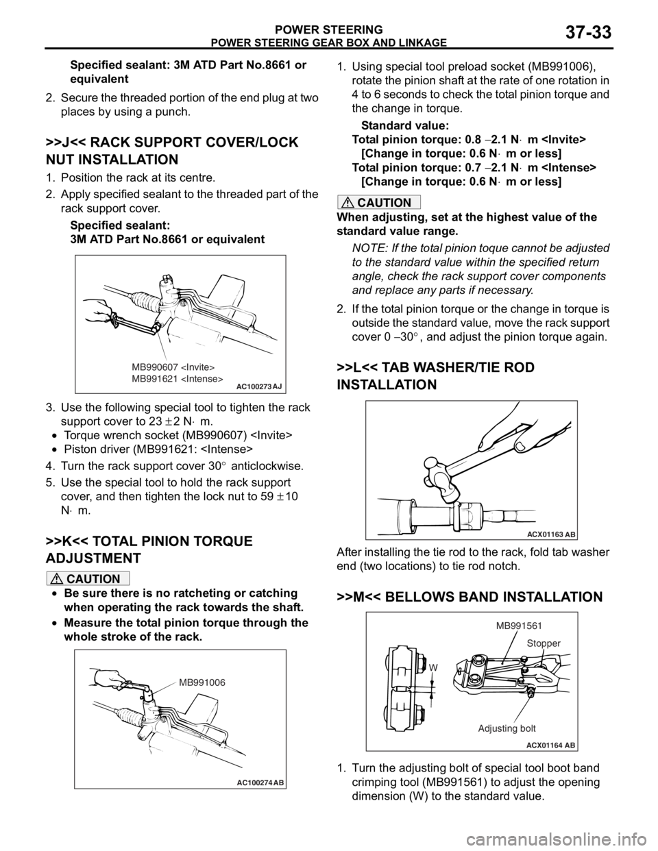
3.Use the fo llo wing special to ol to tigh ten the rack
suppor t cover to 2 3
± 2 N⋅m.
•To rque wren ch socket (MB990607 )
•Piston driver (MB9916 21:
4.T u rn the rack suppo rt cover 30° anticlockwise .
5.Use the special tool to hold the r a ck sup port
cove r , and t hen tighten the lock nut to 59
± 10
N
⋅m.
>>K<< T O T A L PINION T O RQUE
ADJUSTMENT
CAUTION
•Be sure there is no ratcheting or catching
when operating the rack towards the shaft.
•
AC100274 AB
MB991006
Measure the total pinion torque through the
whole stroke of the rack.
1. Using special tool preload socket (MB991006),
rotate the pinion shaft at the rate of one rotation in
4 to 6 seconds to check the total pinion torque and
the change in torque.
Standard value:
Total pinion torque: 0.8 − 2.1 N⋅m
[Change in torque: 0.6 N
⋅m or less]
Total pinion torque: 0.7 − 2.1 N⋅m
[Change in torque: 0.6 N
⋅m or less]
CAUTION
When adjusting, set at the highest value of the
standard value range.
NOTE: If the total pinion toque cannot be adjusted
to the standard value within the specified return
angle, check the rack support cover components
and replace any parts if necessary.
2. If the total pinion torque or the change in torque is outside the standard value, move the rack support
cover 0
− 30°, and adjust the pinion torque again.
>>L<< TAB WASHER/TIE ROD
INSTALLATION
ACX01163 AB
After installing the tie rod to the rack, fold tab washer
end (two locations) to tie rod notch.
>>M<< BELLOWS BAND INSTALLATION
ACX01164 AB
W MB991561
Adjusting bolt Stopper
1. Turn the adjusting bolt of special tool boot band
crimping tool (MB991561) to adjust the opening
dimension (W) to the standard value.
Page 273 of 800
42-1
GROUP 42
BODY
CONTENTS
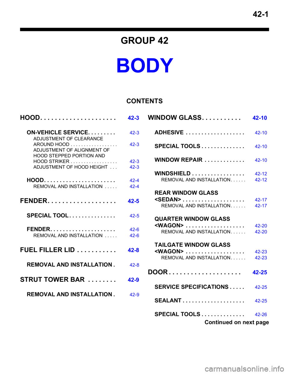
HOOD . . . . . . . . . . . . . . . . . . . . .42-3
ON-VEHICLE SERVICE. . . . . . . . .42-3
ADJUSTMENT OF CLEARANCE
AROUND HOOD . . . . . . . . . . . . . . . . . . 42-3
ADJUSTMENT OF ALIGNMENT OF
HOOD STEPPED PORTION AND
HOOD STRIKER . . . . . . . . . . . . . . . . . . 42-3
ADJUSTMENT OF HOOD HEIGHT . . . 42-3
HOOD . . . . . . . . . . . . . . . . . . . . . . .42-4
REMOVAL AND INSTALLATION . . . . . 42-4
FENDER . . . . . . . . . . . . . . . . . . .42-5
SPECIAL TOOL . . . . . . . . . . . . . . .42-5
FENDER . . . . . . . . . . . . . . . . . . . . .42-6
REMOVAL AND INSTALLATION . . . . . 42-6
FUEL FILLER LID . . . . . . . . . . .42-8
REMOVAL AND INSTALLATION .42-8
STRUT TOWER BAR . . . . . . . .42-9
REMOVAL AND INSTALLATION .42-9
WINDOW GLASS . . . . . . . . . . . 42-10
ADHESIVE . . . . . . . . . . . . . . . . . . .42-10
SPECIAL TOOLS . . . . . . . . . . . . . .42-10
WINDOW REPAIR . . . . . . . . . . . . .42-10
WINDSHIELD . . . . . . . . . . . . . . . . .42-12
REMOVAL AND INSTALLATION . . . . . . 42-12
REAR WINDOW GLASS
REMOVAL AND INSTALLATION . . . . . . 42-17
QUARTER WINDOW GLASS
REMOVAL AND INSTALLATION . . . . . . 42-20
TAILGATE WINDOW GLASS
REMOVAL AND INSTALLATION . . . . . . 42-23
DOOR . . . . . . . . . . . . . . . . . . . . 42-25
SERVICE SPECIFICA TIONS . . . . .42-25
SEALANT . . . . . . . . . . . . . . . . . . . .42-25
SPECIAL TOOLS . . . . . . . . . . . . . .42-26
Continued on next page
Page 281 of 800
STRUT TOWER BAR
BODY42-9
STRUT TOWER BAR
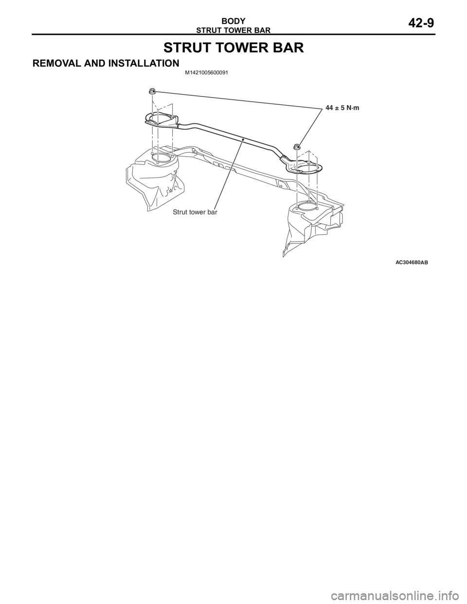
REMOVAL AND INSTALLATIONM1421005600091
AC304680AB
Strut tower bar44 ± 5 N·m
Page 299 of 800
DOOR
BODY42-27
ON-VEHICLE SERVICE
DOOR FIT ADJUSTMENT
M1423001100175
CAUTION
•Attach protection tape to the fender and door
edges where the hinge is installed.
•Do not rotate special tool door adjusting
wrench (MB991164) with a torque of over 98
N
⋅m
AC000592
MB990900
or
MB991164
AB
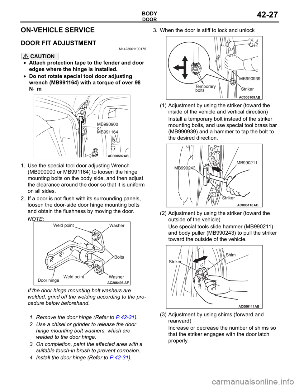
1. Use the special tool door adjusting Wrench (MB990900 or MB991164) to loosen the hinge
mounting bolts on the body side, and then adjust
the clearance around the door so that it is uniform
on all sides.
2. If a door is not flush with its surrounding panels,
loosen the door-side d oor hinge mounting bolts
and obtain the flushness by moving the door.
NOTE:
AC206498
Washer Bolts
Washer
Door hinge
AF
Weld point
Weld point
If the door hinge mounting bolt washers are
welded, grind off the welding according to the pro
-
cedure below beforehand.
.
1. Remove the door hinge (Refer to P.42-31).
2. Use a chisel or grinder to release the door
hinge mounting bolt washers, which are
welded to the door hinge.
3. On completion, paint the affected area with a suitable touch-in brush to prevent corrosion.
4. Install the door hinge (Refer to P.42-31).
3. When the door is stiff to lock and unlock
AC006109AB
Temporary
bolts Striker
MB990939
(1) Adjustment by using the striker (toward the
inside of the vehicle and vertical direction)
Install a temporary bolt instead of the striker
mounting bolts, and use special tool brass bar
(MB990939) and a hammer to tap the bolt to
the desired direction.
AC006110
Striker MB990211
MB990243
AB
(2) Adjustment by using the striker (toward the
outside of the vehicle)
Use special tools slide hammer (MB990211)
and body puller (MB990243) to pull the striker
toward the outside of the vehicle.
AC006111AB
Shim
Striker
(3) Adjustment by using shims (forward and rearward)
Increase or decrease the number of shims so
that the striker engages with the door latch
properly.
Page 331 of 800
KEYLESS ENTRY SYSTEM
BODY42-59
REASSEMBLY SERVICE POINT
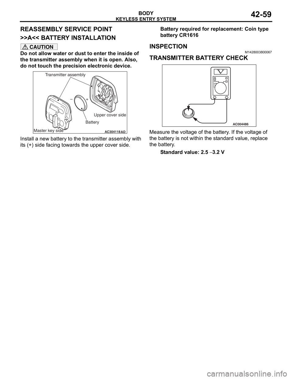
>>A<< BATTERY INSTALLATION
CAUTION
Do not allow water or dust to enter the inside of
the transmitter assembly when it is open. Also,
do not touch the precision electronic device.
AC304118AD
+
–
Master key side Upper cover side
Battery
Transmitter assembly
Install a new battery to the transmitter assembly with
its (+) side facing towards the upper cover side.
Battery required for replacement: Coin type
battery CR1616
INSPECTION
M1428003800067
TRANSMITTER BATTERY CHECK
AC004486
Measure the voltage of the battery. If the voltage of
the battery is not within the standard value, replace
the battery.
Standard value: 2.5 − 3.2 V
Page 352 of 800
DOOR SASH TAPE
EXTERIOR51-20
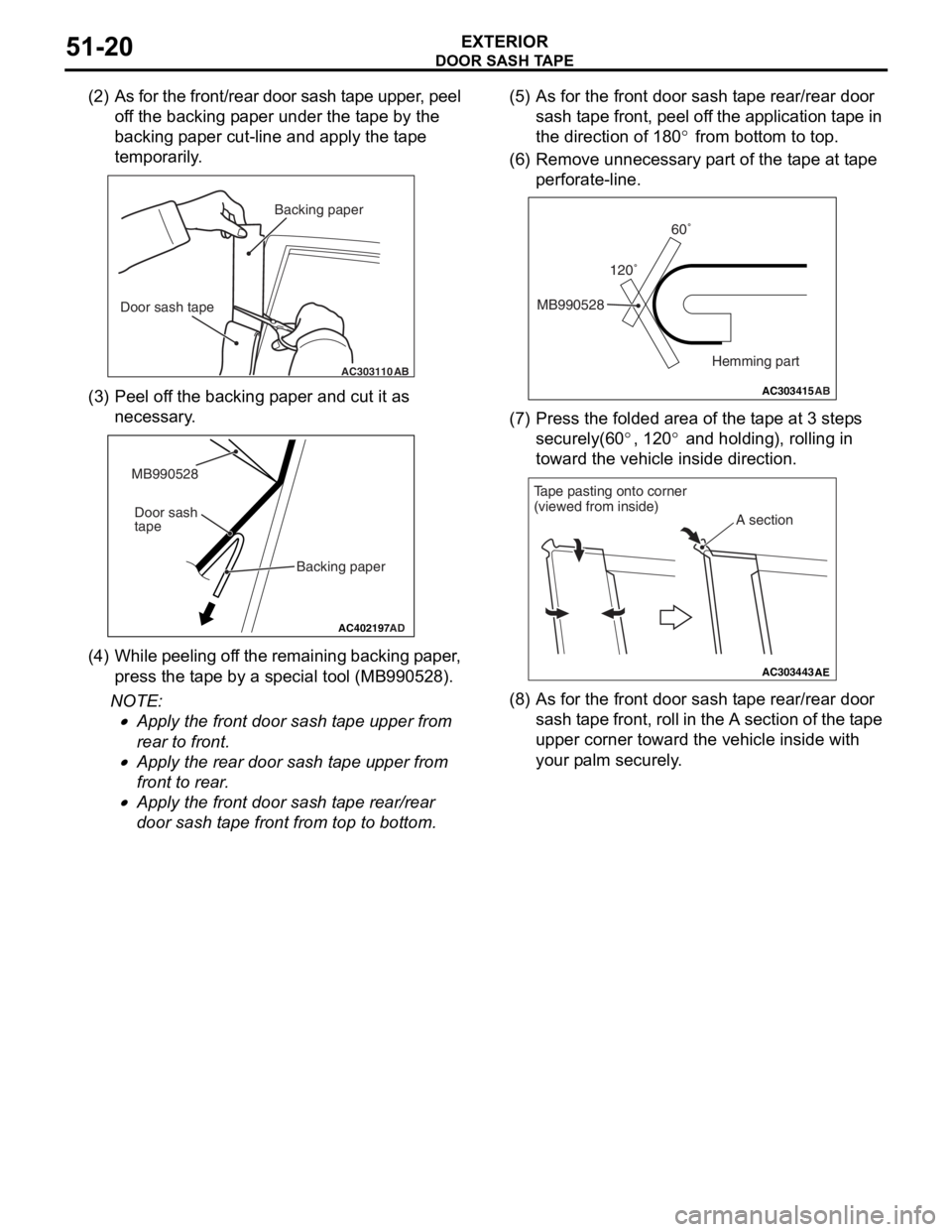
(2) As for the front/rear door sash tape upper, peel off the backing paper under the tape by the
backing paper cut-line and apply the tape
temporarily.
AC303110AB
Backing paper
Door sash tape
(3) P eel o f f th e backin g p aper a nd cu t it a s
necessary .
AC402197AD
MB990528
Backing paper
Door sash
tape
(4
) W hi le pe el in g o f f th e re mai n in g ba ck in g p a pe r ,
press the t a pe by a special to ol (MB99052 8).
NOTE: .
•Apply the fro n t doo r sash t ape u pper fro m
rear to f
r ont.
•Apply the rea r door sash t ape up per from
front to
rear .
•Apply the fro n t doo r sash t ape re ar/rear
door sash
t a p e front from top to b o ttom.
(5) A s fo r the fro n t door sash t ape rea r /rear do or
sash t a pe front, pee l of f the ap plication t a pe in
the d i rection of 180
° from bottom to top.
(6) R emove un nece ssa ry p a rt o f the t ape at t ape
perfo rate-line.
AC303415 AB
MB990528 120˚60˚
Hemming part
(7) P ress the f o lded area o f the t ape at 3 step s
securely(60
°, 12 0° and holding ), rolling in
toward t
he ve
hicle inside direction.
AC303443 AE
A section
Tape pasting onto corner
(viewed from inside)
(8) A s fo r the fro n t door sash t ape rea r /rear do or
sa sh t a pe fro n t, ro ll in t h e A section of th e t a pe
uppe r corn er toward t he ve hicle inside with
you r p a lm sec u rely .