Oil MITSUBISHI LANCER 2006 Manual Online
[x] Cancel search | Manufacturer: MITSUBISHI, Model Year: 2006, Model line: LANCER, Model: MITSUBISHI LANCER 2006Pages: 800, PDF Size: 45.03 MB
Page 269 of 800
POWER STEERING OIL PUMP ASSEMBLY
POWER STEERING37-39
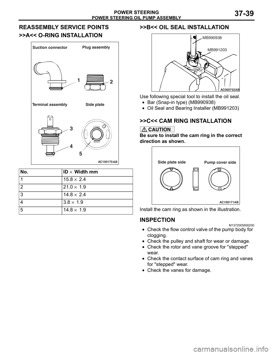
REASSEMBLY SERVICE POINTS
>>A<< O-RING INSTALLATION
AC100170AB
Suction connector Plug assembly
Terminal assembly Side plate
1 2
3
4 5
No.ID × Width mm
115.8 × 2.4
221.0 × 1.9
314.8 × 2.4
43.8 × 1.9
514.8 × 1.9
>>B<< OIL SEAL INST ALLA TION
AC000752
MB990938
AB
MB991203
Use following spe c ia l too l to inst all the oil seal.
•Bar (Snap-in type) (MB9909 38)
•Oil Seal and Bearin g Inst aller (MB9912 03)
>>C<< CAM RING INSTALLA TION
CAUTION
Be sure to install the cam ring in the correct
direction as shown.
AC100171AB
Side plate side
Pump cover side
Install the cam ring as shown in the illustration.
INSPECTION
M1372005500200
•Check the flow control valve of the pump body for
clogging.
•Check the pulley and shaft for wear or damage.
•Check the rotor and vane groove for "stepped"
wear.
•Check the contact surface of cam ring and vanes
for "stepped" wear.
•Check the vanes for damage.
Page 270 of 800
POWER STEERING HOSES
POWER STEERING37-40
POWER STEERING HOSES
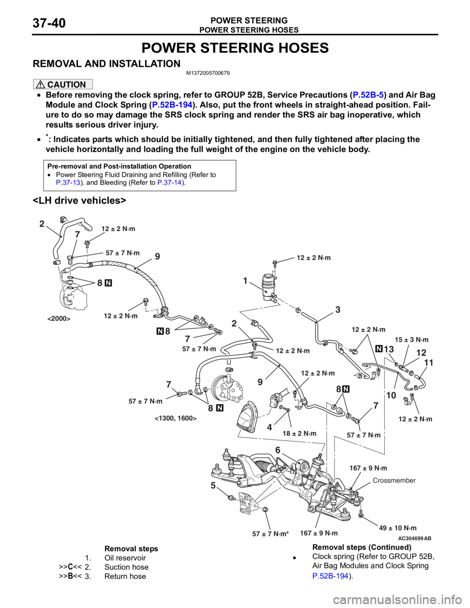
REMOVAL AND INSTALLATIONM1372005700679
CAUTION
•Before removing the clock spring, refer to GROUP 52B, Service Precautions (P.52B-5) and Air Bag
Module and Clock Spring (P.52B-194). Also, put the front wheels in straight-ahead position. Fail-
ure to do so may damage the SRS clock spring and render the SRS air bag inoperative, which
results serious driver injury.
•
Pre-removal and Post-installation Operation
•Power Steering Fluid Draining and Refilling (Refer to P.37-13). and Bleeding (Refer to P.37-14).
*: Indicates parts which should be initially tightened, and then fully tightened after placing the
vehicle horizontally and loading the full weight of the engine on the vehicle body.
AC304699AB
15 ± 3 N·m
18 ± 2 N·m
167 ± 9 N·m
12 ± 2 N·m
49 ± 10 N·m
12 ± 2 N·m
57 ± 7 N·m*57 ± 7 N·m
3
1
2
9
1310
7 11
12
5 68
12 ± 2 N·m
12 ± 2 N·m
2
9
4
7
8
7
8
7
8
57 ± 7 N·m57 ± 7 N·m
57 ± 7 N·m
12 ± 2 N·m
167 ± 9 N·mCrossmember
12 ± 2 N·m
<1300, 1600>
<2000>
12 ± 2 N·m
Removal steps
1.Oil reservoir
>>C<<2.Suction hose
>>B<<3.Return hose
•Clock spring (Refer to GROUP 52B,
Air Bag Modules and Clock Spring
P.52B-194).
Removal steps (Continued)
Page 272 of 800
Removal steps
1.Oil reservoir
>>C<<2.Suction hose
>>B<<3.Return hose
•Clock spring (Refer to GROUP 52B,
Air Bag Modules and Clock Spring
P.52B-194).
•Centermember (Refer to GROUP 32,
Engine Roll Stopper Centermember
P.32-7).
•Front exhaust pipe (Refer to GROUP
15, Exhaust Pipe and Main Muffler
P.15-10).
4.Steering gear and joint connecting bolt
5.Rear roll stopper connecting bolt
<>6.Eye bolt
7.Gasket
8.Pressure hose assembly
<>9.Return tube
10.O-ring
POWE R STEERING HOSES
POWER S T E E RING37-42
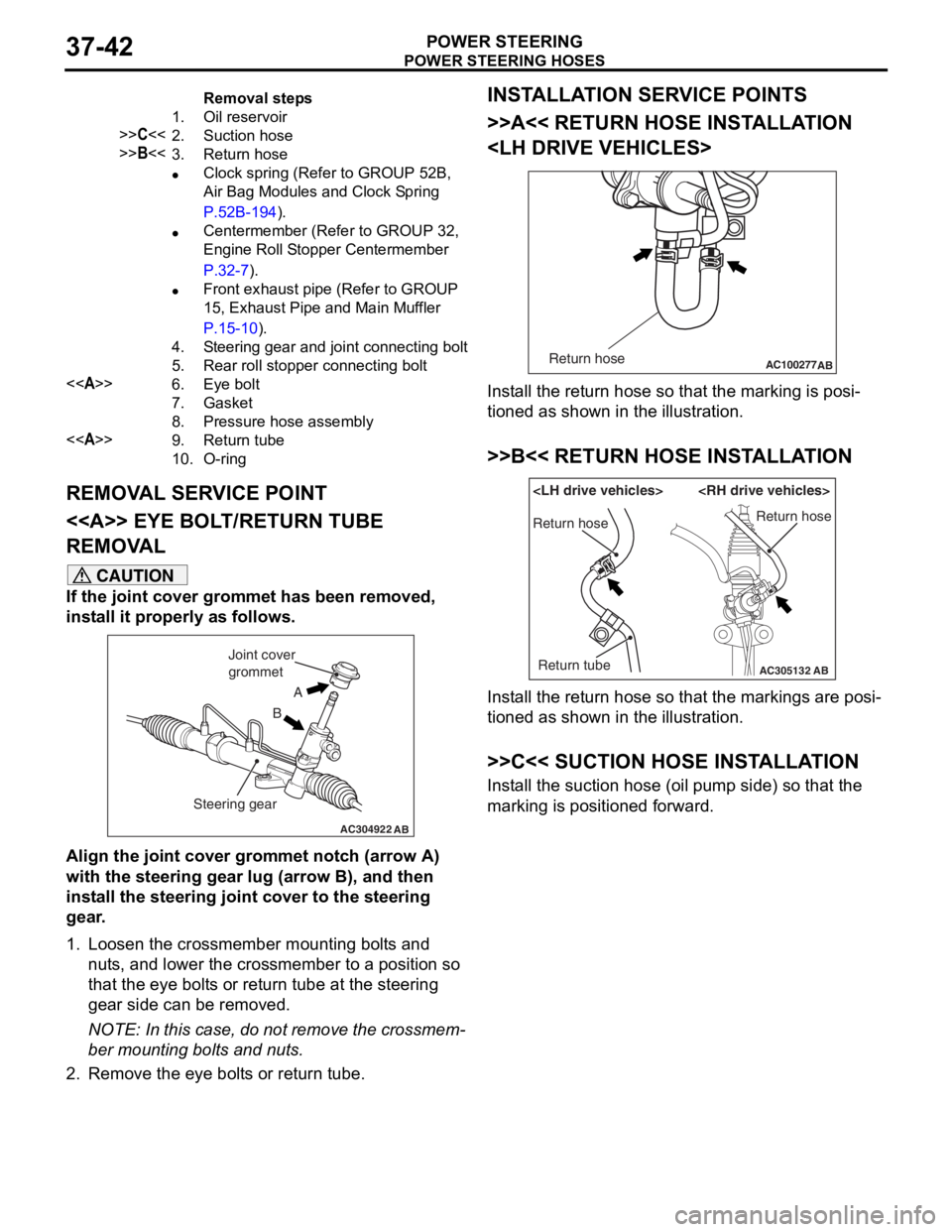
REMOVA L SER V ICE POINT
<> EYE BOLT /RETURN TUBE
REMOV
A L
CAUTION
If the joint cover grommet has been removed,
install it properly as follows.
AC304922AB
A
B
Joint cover
grommet
Steering gear
Align the joint cover grommet notch (arrow A)
with the steering gear lug (arrow B), and then
install the steering joint cover to the steering
gear.
1. Loosen the crossmember mounting bolts and nuts, and lower the crossmember to a position so
that the eye bolts or return tube at the steering
gear side can be removed.
NOTE: In this case, do not remove the crossmem-
ber mounting bolts and nuts.
2. Remove the eye bolts or return tube.
INSTALLATION SERVICE POINTS
>>A<< RETURN HOSE INSTALLATION
AC100277 ABReturn hose
Install the return hose so that the marking is posi-
tioned as shown in the illustration.
>>B<< RETURN HOSE INSTALLATION
AC305132AB
Return hose
Return tubeReturn hose
Install the return hose so that the markings are posi-
tioned as shown in the illustration.
>>C<< SUCTION HOSE INSTALLATION
Install the suction hose (oil pump side) so that the
marking is positioned forward.
Page 282 of 800
WINDOW GLASS
BODY42-10
WINDOW GLASS
ADHESIVEM1422000500081
ItemSpecified adhesive
Windshield3M ATD Part No.8609 Super Fast Urethane Auto Glass
Sealant or equivalent
3M ATD Part No.8608 Super Fast Urethane Primer or
equivalentRear window glass
Quarter window glass
Tailgate window glass
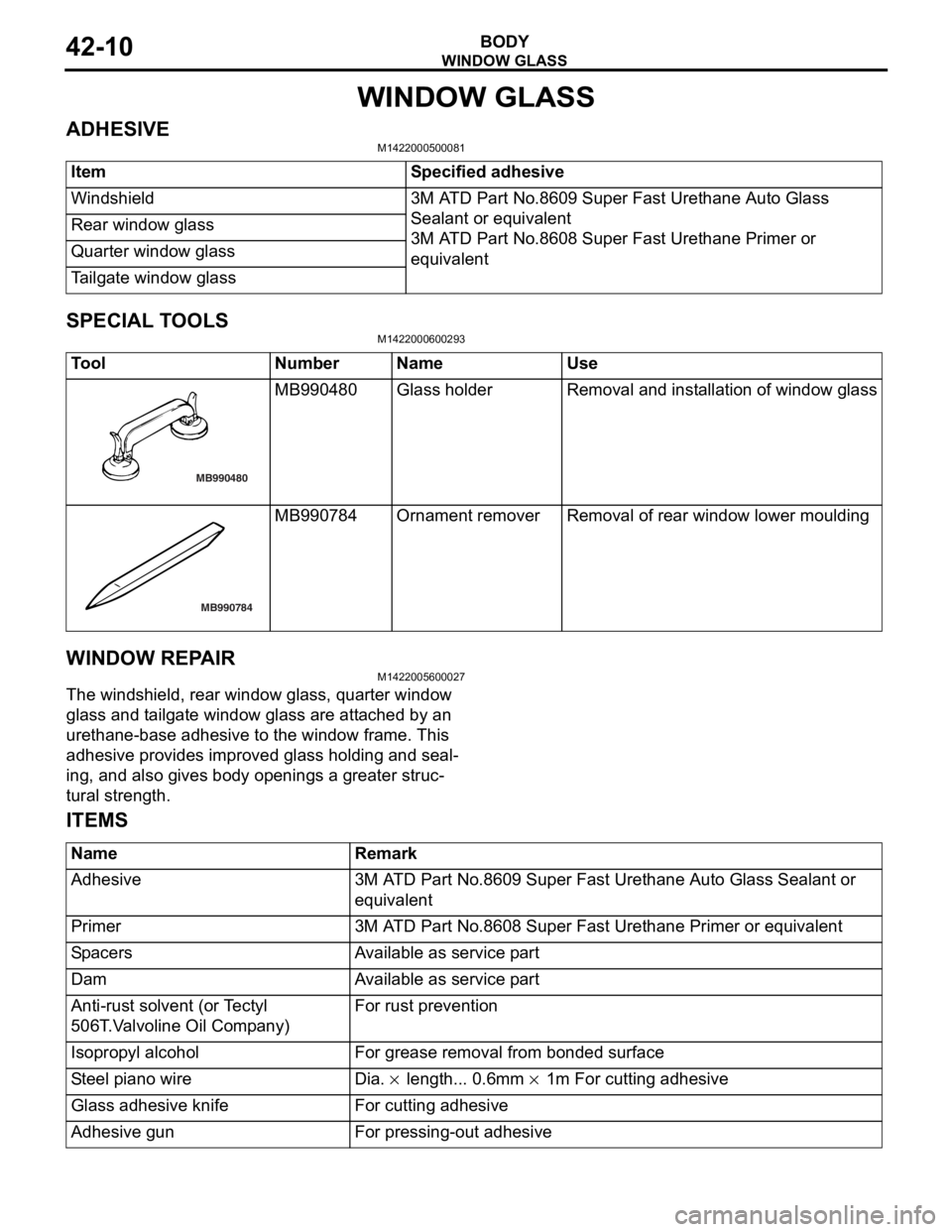
SPECIAL TOOLS
M1422000600293
ToolNumberNameUse
MB990480
MB990480Gl as s h o l de rRemoval and inst a llat i on of wind ow glass
MB990784
MB990784Ornament removerRemoval of rea r window lower mo ulding
WI NDOW REP A IR
M14220056 0002 7
The windshield, rear wind ow glass, q uarter window
glass an
d t a ilg ate win dow gla ss a r e att a ched by an
urethan
e-base adhe sive to the wind ow frame . This
adhesive provides improv
ed glass hold i ng a nd seal
-
ing, and also g i ve s bod y op ening s a g r eater struc-
tural strength.
ITEMS
NameRemark
Adhesive3M ATD Part No.8609 Super Fast Urethane Auto Glass Sealant or
equivalent
Primer3M ATD Part No.8608 Super Fast Urethane Primer or equivalent
SpacersAvailable as service part
DamAvailable as service part
Anti-rust solvent (or Tectyl
506T.Valvoline Oil Company)For rust prevention
Isopropyl alcoholFor grease removal from bonded surface
Steel piano wireDia. × length... 0.6mm × 1m For cutting adhesive
Glass adhesive knifeFor cutting adhesive
Adhesive gunFor pressing-out adhesive
Page 295 of 800
WINDOW GLASS
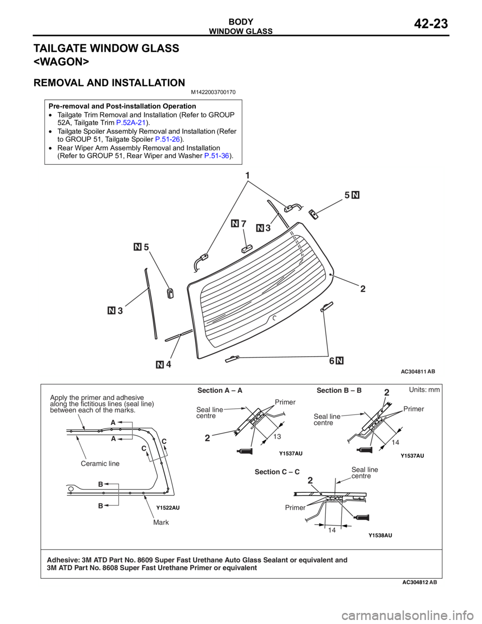
BODY42-23
TAILGATE WINDOW GLASS
REMOVAL AND INSTALLATION
M1422003700170
Pre-removal and Post-installation Operation
•Tailgate Trim Removal and Installation (Refer to GROUP
52A, Tailgate Trim
P.52A-21).
•Tailgate Spoiler Assembly Removal and Installation (Refer
to GROUP 51, Tailgate Spoiler
P.51-26).
•Rear Wiper Arm Assembly Removal and Installation
(Refer to GROUP 51, Rear Wiper and Washer
P.51-36).
AC304811
12
6
5
5
4
3 3
7
AB
N
NN
N
N
N
N
Y1522AU
Y1538AU
AC304812
Y1537AUY1537AU
AB
Units: mm
Adhesive: 3M ATD Part No. 8609 Super Fast Urethane Auto Glass Sealant or equivalent and
3M ATD Part No. 8608 Super Fast Urethane Primer or equivalent Section A – A
13 14
14
Section B – B
Section C – C
A
A CC
B B
Ceramic line
Mark
Apply the primer and adhesive
along the fictitious lines (seal line)
between each of the marks.
Seal line
centre
Primer
Seal line
centre Primer
Seal line
centre
Primer
2 2
2
Page 315 of 800
TRUNK LID
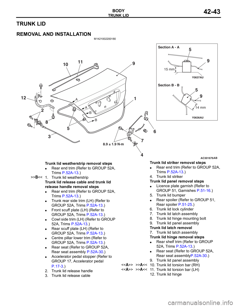
BODY42-43
TRUNK LID
REMOVAL AND INSTALLATION
M1421002200180
AC301676
Y0636AU
Y0637AU
AB
8.9 ± 1.9 N·m
A
AB
B 15 mm
14 mm
Section A - A
Section B - B
9
5
6
4
12
9
59
7
11
10
8 3 5 1
2
Trunk lid weatherstrip removal steps
•Rear end trim (Refer to GROUP 52A,
Trims
P.52A-13.)
>>B<<1.Trunk lid weatherstrip
Trunk lid release cable and trunk lid
release handle removal steps
•Rear end trim (Refer to GROUP 52A,
Trims
P.52A-13.)
•Trunk rear side trim (LH) (Refer to
GROUP 52A, Trims
P.52A-13.)
•Front scuff plate (LH) (Refer to
GROUP 52A, Trims
P.52A-13.)
•Cowl side trim (LH) (Refer to GROUP
52A, Trims
P.52A-13.)
•Rear scuff plate (LH) (Refer to
GROUP 52A, Trims
P.52A-13.)
•Centre pillar lower trim (Refer to
GROUP 52A, Trims
P.52A-13.)
•Rear seat (Refer to GROUP 52A,
Rear seat assembly
P.52A-30.)
•Accelerator pedal stopper (Refer to
GROUP 17, Accelerator pedal
P.17-3.)
2.Trunk lid release handle
3.Trunk lid release cable
Trunk lid striker removal steps
•Rear end trim (Refer to GROUP 52A,
Trims
P.52A-13.)
4.Trunk lid striker
Trunk lid panel removal steps
•Licence plate garnish (Refer to
GROUP 51, Garnishes
P.51-16.)
5.Trunk lid bumper
•Rear spoiler (Refer to GROUP 51,
Rear spoiler
P.51-25.)
6.Trunk lid lock cylinder
7.Trunk lid latch assembly
8.Trunk lid hinge mounting bolt
9.Trunk lid panel assembly
Trunk lid latch removal
7.Trunk lid latch assembly
Trunk lid hinge removal steps
•Rear shelf trim (Refer to GROUP
52A, Trims
P.52A-13.)
•Rear seat (Refer to GROUP 52A,
Rear seat assembly
P.52A-30.)
9.Trunk lid panel assembly
<>>>A<<10.Trunk lid torsion bar (RH)
<>>>A<<11 .Trunk lid torsion bar (LH)
12.Trunk lid hinge
Page 317 of 800
TRUNK LID
BODY42-45
CAUTION
Install the trunk lid torsion bar
trunk lid torsion bar
reversed, the trunk lid torsion bar
be able to be installed because the special tool
will interfere with the trunk lid torsion bar
during installation of the trunk lid torsion bar
1. Identify the LH and RH torsion bars by the colour mark made at the centre of each torsion bar.
Trunk lid torsion barMark
colour
LHVehicles with rear spoilerGreen
Vehicles without rear spoilerWhite
green
RHVehicles with rear spoilerYe l l o w
Vehicles without rear spoilerRed
2. Insert the left end of the trunk lid torsion bar
3. Press portion A of the trunk lid torsion bar
right end against point A on the trunk lid hinge
4. Twist the portion B of the trunk lid torsion bar
moved from point B and pressed against point C
of the trunk lid hinge
Then force the portion into point D.
5. Twist the portion A of the trunk lid torsion bar
lid hinge
6. Attach the trunk lid torsion bar
trunk lid torsion bar
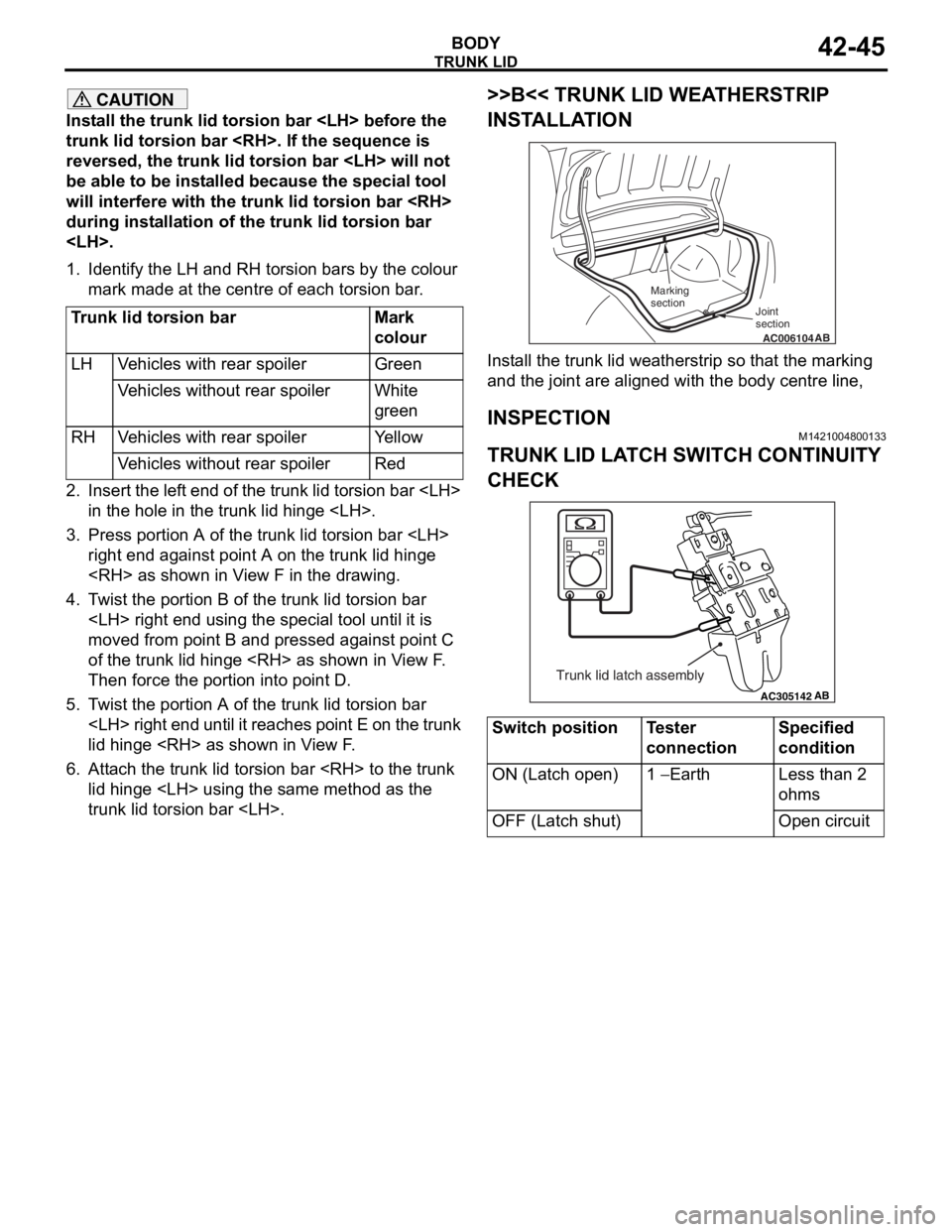
>>B<< TRUNK LID WEATHERSTRIP
INSTALLATION
AC006104AB
Joint
section
Marking
section
Install the trunk lid weatherstrip so that the marking
and the joint are aligned with the body centre line,
INSPECTION
M1421004800133
TRUNK LID LATCH SWITCH CONTINUITY
CHECK
AC305142AB
Trunk lid latch assembly
Switch positionTester
connectionSpecified
condition
ON (Latch open)1 − Earth Less than 2
ohms
OFF (Latch shut)Open circuit
Page 320 of 800
TAILGATE
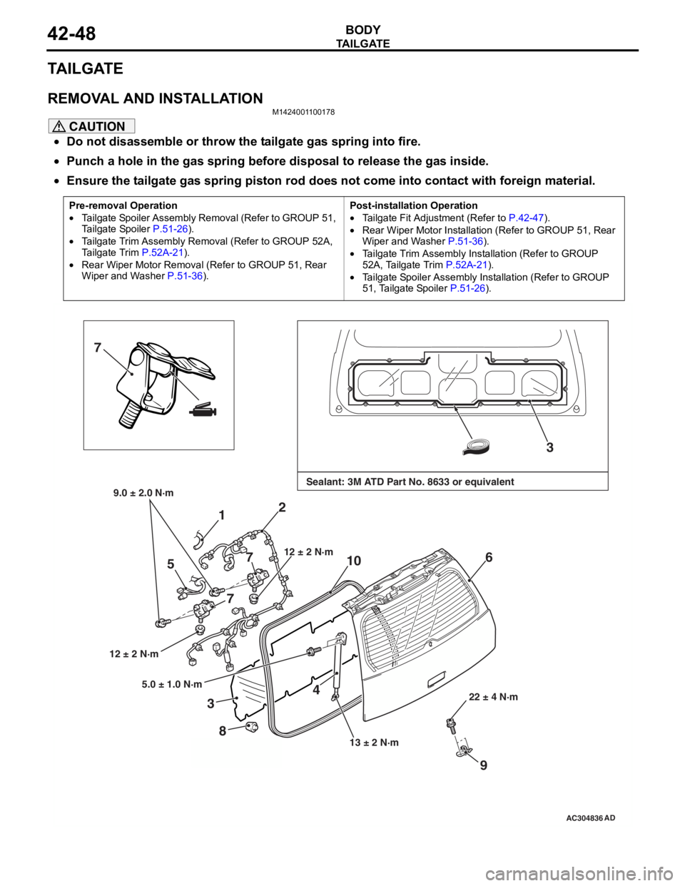
BODY42-48
TA I L G AT E
REMOVAL AND INSTALLATION
M1424001100178
CAUTION
•Do not disassemble or throw the tailgate gas spring into fire.
•Punch a hole in the gas spring before disposal to release the gas inside.
•
Pre-removal Operation
•Tailgate Spoiler Assembly Removal (Refer to GROUP 51,
Tailgate Spoiler
P.51-26).
•Tailgate Trim Assembly Removal (Refer to GROUP 52A,
Tailgate Trim
P.52A-21).
•Rear Wiper Motor Removal (R efer to GROUP 51, Rear
Wiper and Washer
P.51-36).
Post-installation Operation
•Tailgate Fit Adjustment (Refer to P.42-47).
•Rear Wiper Motor Installation (Refer to GROUP 51, Rear
Wiper and Washer P.51-36).
•Tailgate Trim Assembly Installation (Refer to GROUP
52A, Tailgate Trim P.52A-21).
•Tailgate Spoiler Assembly Installation (Refer to GROUP
51, Tailgate Spoiler P.51-26).
AC304836
7
3
4
1
6
8
12 ± 2 N·m 13 ± 2 N·m22 ± 4 N·m
AD
Sealant: 3M ATD Part No. 8633 or equivalent9.0 ± 2.0 N·m
2
712 ± 2 N·m
5
7
9
5.0 ± 1.0 N·m
3
10
Ensure the tailgate gas spring piston rod does not come into contact with foreign material.
Page 333 of 800
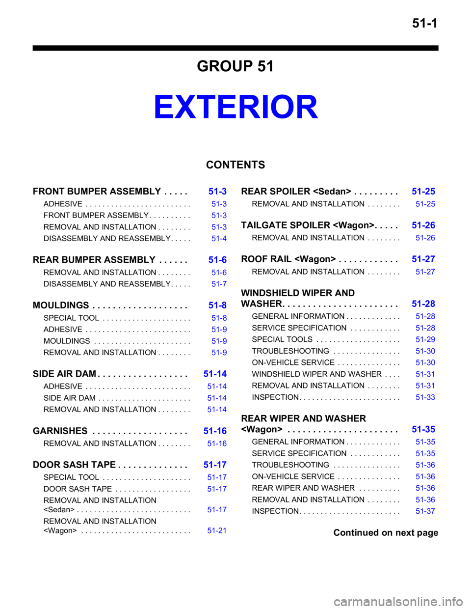
51-1
GROUP 51
EXTERIOR
CONTENTS
FRONT BUMPER ASSEMBLY . . . . .51-3
ADHESIVE . . . . . . . . . . . . . . . . . . . . . . . . . 51-3
FRONT BUMPER ASSEMBLY . . . . . . . . . . 51-3
REMOVAL AND INSTALLATION . . . . . . . . 51-3
DISASSEMBLY AND REASSEMBLY . . . . . 51-4
REAR BUMPER ASSEMBLY . . . . . .51-6
REMOVAL AND INSTALLATION . . . . . . . . 51-6
DISASSEMBLY AND REASSEMBLY . . . . . 51-7
MOULDINGS . . . . . . . . . . . . . . . . . . .51-8
SPECIAL TOOL . . . . . . . . . . . . . . . . . . . . . 51-8
ADHESIVE . . . . . . . . . . . . . . . . . . . . . . . . . 51-9
MOULDINGS . . . . . . . . . . . . . . . . . . . . . . . 51-9
REMOVAL AND INSTALLATION . . . . . . . . 51-9
SIDE AIR DAM . . . . . . . . . . . . . . . . . .51-14
ADHESIVE . . . . . . . . . . . . . . . . . . . . . . . . . 51-14
SIDE AIR DAM . . . . . . . . . . . . . . . . . . . . . . 51-14
REMOVAL AND INSTALLATION . . . . . . . . 51-14
GARNISHES . . . . . . . . . . . . . . . . . . .51-16
REMOVAL AND INSTALLATION . . . . . . . . 51-16
DOOR SASH TAPE . . . . . . . . . . . . . .51-17
SPECIAL TOOL . . . . . . . . . . . . . . . . . . . . . 51-17
DOOR SASH TAPE . . . . . . . . . . . . . . . . . . 51-17
REMOVAL AND INSTALLATION
REMOVAL AND INSTALLATION
REAR SPOILER
REMOVAL AND INSTALLATION . . . . . . . . 51-25
TAILGATE SPOILER
REMOVAL AND INSTALLATION . . . . . . . . 51-26
ROOF RAIL
REMOVAL AND INSTALLATION . . . . . . . . 51-27
WINDSHIELD WIPER AND
WASHER. . . . . . . . . . . . . . . . . . . . . . .51-28
GENERAL INFORMATION . . . . . . . . . . . . . 51-28
SERVICE SPECIFICATION . . . . . . . . . . . . 51-28
SPECIAL TOOLS . . . . . . . . . . . . . . . . . . . . 51-29
TROUBLESHOOTING . . . . . . . . . . . . . . . . 51-30
ON-VEHICLE SERVICE . . . . . . . . . . . . . . . 51-30
WINDSHIELD WIPER AND WASHER . . . . 51-31
REMOVAL AND INSTALLATION . . . . . . . . 51-31
INSPECTION. . . . . . . . . . . . . . . . . . . . . . . . 51-33
REAR WIPER AND WASHER
GENERAL INFORMATION . . . . . . . . . . . . . 51-35
SERVICE SPECIFICATION . . . . . . . . . . . . 51-35
TROUBLESHOOTING . . . . . . . . . . . . . . . . 51-36
ON-VEHICLE SERVICE . . . . . . . . . . . . . . . 51-36
REAR WIPER AND WASHER . . . . . . . . . . 51-36
REMOVAL AND INSTALLATION . . . . . . . . 51-36
INSPECTION. . . . . . . . . . . . . . . . . . . . . . . . 51-37
Continued on next page
Page 357 of 800
REAR SPOILER
EXTERIOR51-25
REAR SPOILER
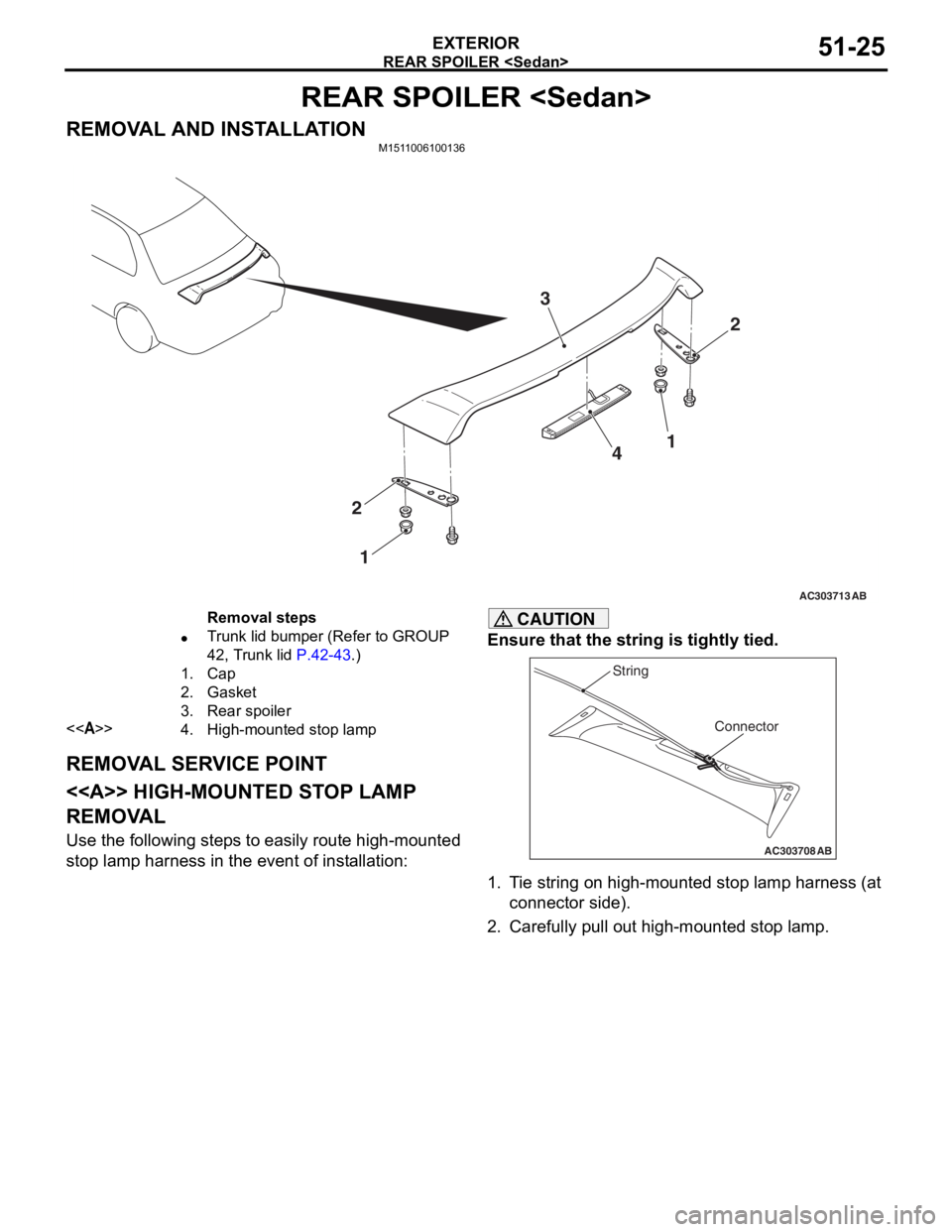
REMOVAL AND INSTALLATIONM1511006100136
AC303713
2
3
4
2 1
AB
1
Removal steps
•Trunk lid bumper (Refer to GROUP
42, Trunk lid
P.42-43.)
1.Cap
2.Gasket
3.Rear spoiler
<>4.High-mounted stop lamp
REMOV A L SER V ICE POINT
< > HIGH-MOUNTED ST OP LAMP
REMOV
A L
Use the following step s to ea sily ro ute high-mounted
stop
lamp harne ss in the eve n t of inst allation:
CAUTION
Ensure that the string is tightly tied.
AC303708
Connector
String
AB
1. Tie string on high-mounted stop lamp harness (at
connector side).
2. Carefully pull out high-mounted stop lamp.