Oil MITSUBISHI LANCER 2006 Repair Manual
[x] Cancel search | Manufacturer: MITSUBISHI, Model Year: 2006, Model line: LANCER, Model: MITSUBISHI LANCER 2006Pages: 800, PDF Size: 45.03 MB
Page 200 of 800
GENERAL INFORMATION
REAR SUSPENSION34-2
GENERAL INFORMATION
M1341000100717
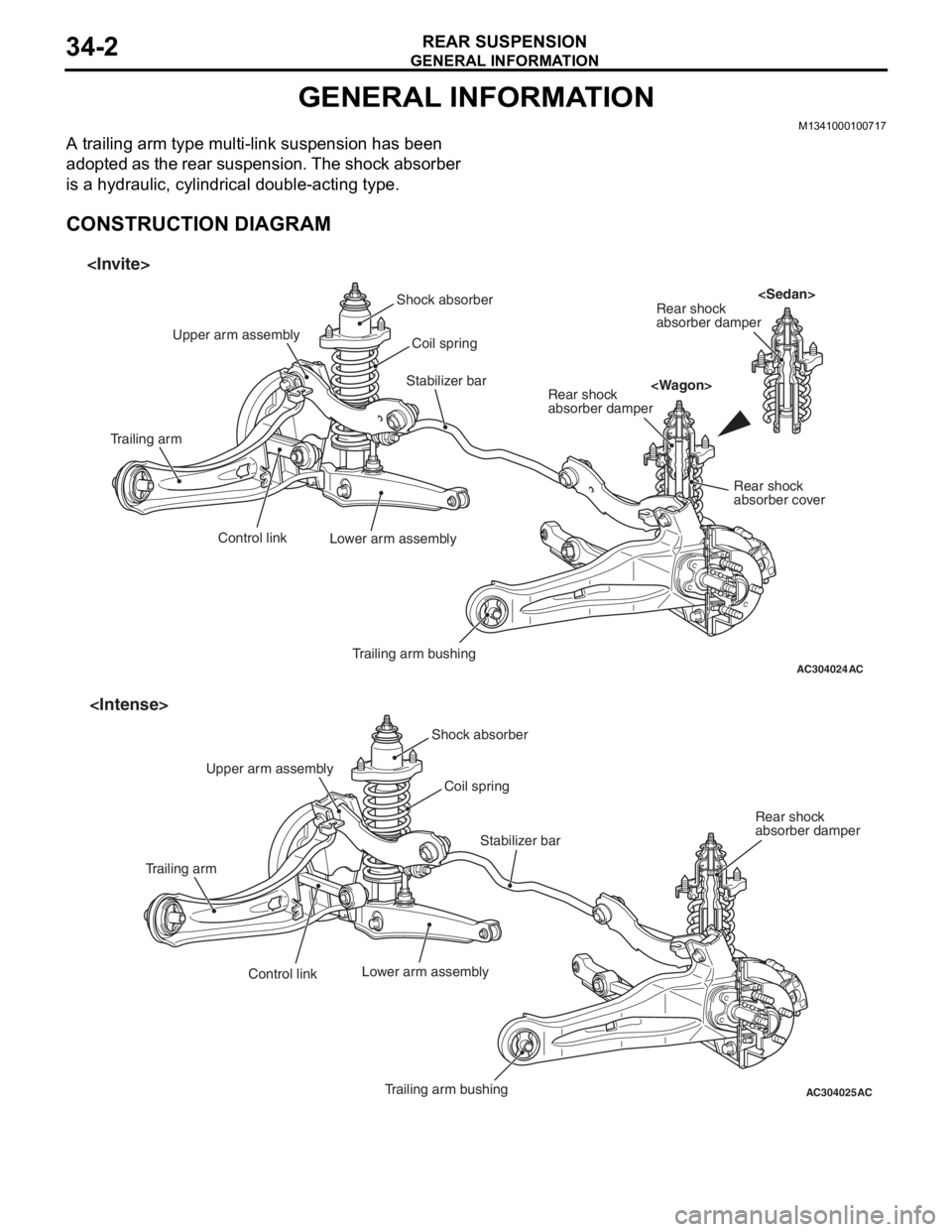
A trailing arm type multi-link suspension has been
adopted as the rear suspension. The shock absorber
is a hydraulic, cylindrical double-acting type.
CONSTRUCTION DIAGRAM
AC304024AC
Shock absorberCoil spring
Trailing arm bushing
Lower arm assembly
Control link
Trailing arm Upper arm assembly
Stabilizer barRear shock
absorber damper
Rear shock
absorber damper Rear shock
absorber cover
AC304025AC
Shock absorber
Trailing arm bushing
Control link
Trailing arm
Stabilizer bar
Coil spring
Lower arm assembly
Rear shock
absorber damper
Upper arm assembly
Page 201 of 800

SERVICE SPECIFICATIONS
REAR SUSPENSION34-3
SPECIFICATION
COIL SPRING
ItemSedanWagon
InviteIntenseInviteIntense
Wire diameter mm10101010
Average diameter mm78 − 9078 − 9078 − 9078 − 90
Free length mm359331377368
SERVICE SPECIFICATIONS
M1341000300733
ItemStandard value
Camber (Difference between right and left within 30') −0°40' ± 0°30'
Toe-inAt the centre of tyre tread mm3 ± 2
Toe-angle (per wheel)0°08' ± 0°05'
Thrust angle0°00' ± 0°09'
Control link pillow ball bushing starting torque
Upper arm pillow ball bushing starting torque
Lower arm pillow ball bushing starting torque N⋅m0.5 − 3.0
Protruding length of stabilizer link bolt mm6 − 8
Stabilizer link ball joint continuous turning torque N⋅m0.5 − 1.5
LUBRICANT
M1341000400172
ItemSpecified lubricantQuantity
Stabilizer link ball joint (inside of dust cover)Multipurpose grease SAE J310, NLGI No.2
or equivalentAs required
Page 203 of 800
MB990947
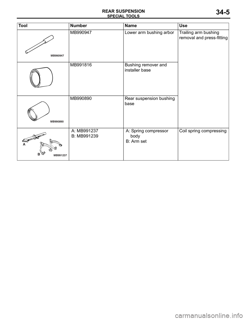
SPECIA L T OOLS
REAR SU SPENS I ON34-5
MB990947Lower arm bushing arborTr a iling arm bushing
re
moval and press-fit t ing
MB991816Bushing remove r and
inst
al ler b a se
MB990890
MB990890Rear suspension bushing
base
MB991237
A
B
A: MB9912 37
B: MB991239
A: Sp ring compressor
bo dy
B: Arm set
Coil spring compressing
Tool Nu mber Na me Use
Page 213 of 800
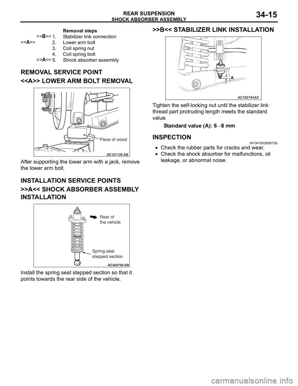
Removal steps
>>B<<1.Stabilizer link connection
<>2.Lower arm bolt
3.Coil spring nut
4.Coil spring bolt
>>A<<5.Shock absorber assembly
SHOCK ABSORBER ASSEMBLY
REAR SUSPENSION34-15
REMOVAL SERVICE POINT
<> LOWER ARM BOLT REMOVAL
AC107126AB
Piece of wood
After suppo rting the lo we r arm with a jack, remove
the lo
we r arm b o lt.
INSTALLA T ION SER VICE POINT S
>>A<< SHOCK ABSORBER ASSEMBL Y
INST
ALLA TION
AC304795 AB
Spring seat
stepped section
Rear of
the vehicle
Install the sprin g se at ste pped section so th at it
point
s towards the rea r side of th e ve hicle.
>>B<< STABILIZER LINK INST ALLA TION
AC103744
A
AC
Ti ghten the self-locking nut un til t he st ab ilizer link
thread
p a rt protrud i ng length mee t s the st a ndard
value.
St andard va lue (A): 6 − 8 mm
INSPECTIONM13410026 0015 0
•Check the rubbe r p a rt s for cracks a nd wear .
•Check the sho c k abso r ber for malfunct i ons, oil
le
akag e, or a bnormal no ise .
Page 214 of 800
SHOCK ABSORBER ASSEMBLY
REAR SUSPENSION34-16
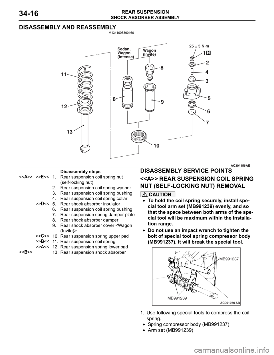
DISASSEMBLY AND REASSEMBLY
M1341005300460
AC304156AE
25 ± 5 N·m
1
2
4
5
3
6
7
8
9
11
13
12
10
8
Wagon
(Invite)
Sedan,
Wagon
(Intense)
Disassembly steps
<>>>E<<1.Rear suspension coil spring nut
(self-locking nut)
2.Rear suspension coil spring washer
3.Rear suspension coil spring bushing
4.Rear suspension coil spring collar
>>D<<5.Rear shock absorber insulator
6.Rear suspension coil spring bushing
7.Rear suspension spring damper plate
8.Rear shock absorber damper
9.Rear shock absorber cover
>>C<<10.Rear suspension spring upper pad
>>B<<11 .Rear suspension coil spring
>>A<<12.Rear suspension spring lower pad
<>13.Rear suspension shock absorber
DISASSEMBL
Y SER V ICE POINTS
<> REAR SUSPENSION COIL SPRING
NUT (SELF-LOCKING NUT) REMOV
A L
CAUTION
•To hold the coil spring securely, install spe-
cial tool arm set (MB991239) evenly, and so
that the space between both arms of the spe
-
cial tool will be maximum within the installa-
tion range.
•
AC001070
MB991237
MB991239
AB
Do not use an impact wrench to tighten the
bolt of special tool spring compressor body
(MB991237). It will break the special tool.
1. Use following special tools to compress the coil spring.
•Spring compressor body (MB991237)
•Arm set (MB991239)
Page 215 of 800
SHOCK ABSORBER ASSEMBLY
REAR SUSPENSION34-17
WARNING
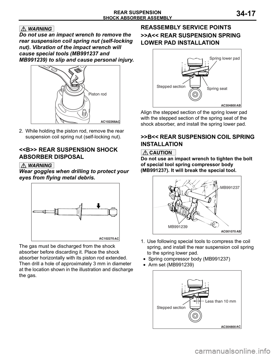
Do not use an impact wrench to remove the
rear suspension coil spring nut (self-locking
nut). Vibration of the impact wrench will
cause special t ools (MB991237 and
MB991239) to slip and cause personal injury.
AC102268AC
Piston rod
2. While holding the piston rod, remove the rear
suspension coil spring nut (self-locking nut).
<> REAR SUSPENSION SHOCK
ABSORBER DISPOSAL
WARNING
Wear goggles when dril ling to protect your
eyes from flying metal debris.
AC102270
AC
The gas must be discharged from the shock
absorber before discarding it. Place the shock
absorber horizontally with its piston rod extended.
Then drill a hole of approximately 3 mm in diameter
at the location shown in the illustration and discharge
the gas.
REASSEMBLY SERVICE POINTS
>>A<< REAR SUSPENSION SPRING
LOWER PAD INSTALLATION
AC304800AB
Spring lower pad
Stepped section
Spring seat
Align the stepped section of the spring lower pad
with the stepped section of the spring seat of the
shock absorber, and install the spring lower pad.
>>B<< REAR SUSPENSION COIL SPRING
INSTALLATION
CAUTION
Do not use an impact wrench to tighten the bolt
of special tool spring compressor body
(MB991237). It will break the special tool.
AC001070
MB991237
MB991239
AB
1. Use following special tools to compress the coil spring, and install the rear suspension coil spring
to the spring lower pad.
•Spring compressor body (MB991237)
•
AC304800AC
Less than 10 mm
Stepped section
Arm set (MB991239)
Page 216 of 800
SHOCK ABSORBER ASSEMBLY
REAR SUSPENSION34-18
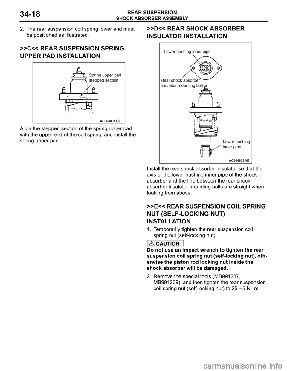
2. The rear suspension coil spring lower end must be positioned as illustrated.
>>C<< REAR SUSPENSION SPRING
UPPER PAD INSTALLATION
AC304801AC
Spring upper pad
stepped section
Align the stepped section of the spring upp er p ad
with the
upper e nd of the coil spring, and inst a ll th e
spring upp
er p ad.
>>D<< REAR SHOCK ABSORBER
INSULA T O R INST AL LA TION
AC304802
Lower bushing inner pipe
Rear shock absorber
insulator mounting bolt
AB
Lower bushing
inner pipe
Inst all the r ear sh ock absorber insu lator so tha t the
axis of t
he lo we r bush i ng inner pipe of the shock
abso
r ber and the line b e tween t he rear shock
abso
r ber in sulator mounting bo lt s are straight when
looking from
a bove .
>>E<< REAR SUSPENSI ON COIL SPRING
NUT (SELF-LOCKING NUT)
INST
ALLA TION
1.T e mp orarily tighten the rea r suspension coil
sprin g nut (self-locking nut).
CAUTION
Do not use an impact wrench to tighten the rear
suspension coil spring nut (self-locking nut), oth
-
erwise the piston rod locking nut inside the
shock absorber will be damaged.
2. Remove the special tools (MB991237,
MB991239), and then tighten the rear suspension
coil spring nut (self-locking nut) to 25
± 5 N⋅m.
Page 231 of 800
37-1
GROUP 37
POWER STEERING
CONTENTS
GENERAL INFORMATION . . . . . . . .37-3
SERVICE SPECIFICATIONS . . . . . . .37-6
LUBRICANTS . . . . . . . . . . . . . . . . . .37-7
SEALANTS . . . . . . . . . . . . . . . . . . . .37-7
SPECIAL TOOLS . . . . . . . . . . . . . . . .37-8
ON-VEHICLE SERVICE . . . . . . . . . . .37-11
STEERING WHEEL FREE PLAY CHECK . 37-11
STEERING ANGLE CHECK . . . . . . . . . . . . 37-11
TIE ROD END BALL JOINT TURNING
TORQUE CHECK . . . . . . . . . . . . . . . . . . . . 37-12
STATIONARY STEERING EFFORT
CHECK . . . . . . . . . . . . . . . . . . . . . . . . . . . . 37-12
STEERING WHEEL RETURN TO
CENTRE CHECK . . . . . . . . . . . . . . . . . . . . 37-13
DRIVE BELT TENSION CHECK. . . . . . . . . 37-13
FLUID LEVEL CHECK . . . . . . . . . . . . . . . . 37-13
FLUID REPLACEMENT . . . . . . . . . . . . . . . 37-13
POWER STEERING SYSTEM AIR
BLEEDING . . . . . . . . . . . . . . . . . . . . . . . . . 37-14
OIL PUMP PRESSURE TEST . . . . . . . . . . 37-14
POWER STEERING PRESSURE
SWITCH CHECK . . . . . . . . . . . . . . . . . . . . . 37-15
TIE ROD END BALL JOINT DUST
COVER CHECK . . . . . . . . . . . . . . . . . . . . . 37-15
STEERING COLUMN SHAFT ASSEMBLY
SHOCK ABSORBING MECHANISM
CHECK . . . . . . . . . . . . . . . . . . . . . . . . . . . . 37-15
STEERING WHEEL . . . . . . . . . . . . . .37-17
REMOVAL AND INSTALLATION
REMOVAL AND INSTALLATION
Continued on next page
WARNINGS REGARDING SERVICING OF SUPPLEMENTAL RESTRAINT SYSTEM (SRS) EQUIPPED VEHICLES
WARNING
•Improper service or maintenance of any component of the SRS, or any SRS-related component, can lead to
personal injury or death to service personnel (from inad vertent firing of the air bag) or to the driver and
paassenger (from renderin g the SRS inoperative).
•Service or maintenance of any SRS component or SRS-related component must be performed only at an
authorized MITSUBISHI dealer.
•MITSUBISHI dealer personnel must thoroughly review th is manual, and especially its GROUP 52B - Supplemental
Restraint System (SRS) before begi nning any service or maintenance of any component of the SRS or any
SRS-related component.
NOTE
The SRS includes the following components: SRS air bag control unit, SRS warning light, front impact sensors, air bag module,
clock spring, and interconnecting wiring. Other SRS-related components (that may have to be removed/installed in connection
with SRS service or maintenance) are indicated in the table of contents by an asterisk (*).
Page 232 of 800
37-2
STEERING COLUMN SHAFT
ASSEMBLY . . . . . . . . . . . . . . . . . . . .37-20
REMOVAL AND INSTALLATION . . . . . . . . 37-20
DISASSEMBLY AND REASSEMBLY . . . . . 37-22
POWER STEERING GEAR BOX AND
LINKAGE . . . . . . . . . . . . . . . . . . . . . .37-23
REMOVAL AND INSTALLATION . . . . . . . . 37-23
INSPECTION . . . . . . . . . . . . . . . . . . . . . . . 37-24
DISASSEMBLY AND REASSEMBLY . . . . . 37-26
TIE ROD END BALL JOINT DUST COVER
REPLACEMENT . . . . . . . . . . . . . . . . . . . . . 37-35
POWER STEERING OIL PUMP
ASSEMBLY. . . . . . . . . . . . . . . . . . . . .37-35
REMOVAL AND INSTALLATION . . . . . . . . 37-35
INSPECTION. . . . . . . . . . . . . . . . . . . . . . . . 37-36
DISASSEMBLY AND REASSEMBLY . . . . . 37-37
INSPECTION. . . . . . . . . . . . . . . . . . . . . . . . 37-39
POWER STEERING HOSES . . . . . . .37-40
REMOVAL AND INSTALLATION . . . . . . . . 37-40
Page 233 of 800

GENERAL INFORMATION
POWER STEERING37-3
GENERAL INFORMATION
M1372000100661
Power steering has been adopted in all vehicles to
make the steering system easier to handle.
FEATURES
•A 4-spoke steering wheel is used.
•MOMO leather-wrapped 3-spoke steering wheel
is used.
•A steering column has a shock absorbing mecha-
nism and a tilt steering mechanism.
•Integral-type rack and pinion gear with high rigid-
ity and excellent response is used.
•A vane type pump with a fluid flow rate control
system which change steering effort according to
the engine speed is used.
•The separate plastic resin oil reservoir is used to
reduce weight and to make the fluid level check
-
ing easier.
SPECIFICATIONS
ItemInviteIntense
Steering
wheelTy p e4-spoke typeMOMO leather-wrapped
3-spoke type
Outside diameter mm380365
Maximum number of turns3.193.08
Steering
columnColumn mechanismShock absorbing mechanism and Tilt steering mechanism
Power steering typeIntegral type
Oil pumpTy p eVane pump
Basic discharge amount cm3/rev.7.2 <1300, 1600>
8.1 <2000>
7.2 <1300, 1600>
8.1 <2000>
Relief pressure MPa8.88.8
Reservoir typeSeparate type (plastic)
Pressure switchEquipped
Steering
gearTy p eRack and pinion
Stroke ratio (Rack stroke/Steering
wheel maximum turning radius)45.7445.74
Rack stroke mm146141