Injector MITSUBISHI LANCER 2006 Workshop Manual
[x] Cancel search | Manufacturer: MITSUBISHI, Model Year: 2006, Model line: LANCER, Model: MITSUBISHI LANCER 2006Pages: 800, PDF Size: 45.03 MB
Page 55 of 800
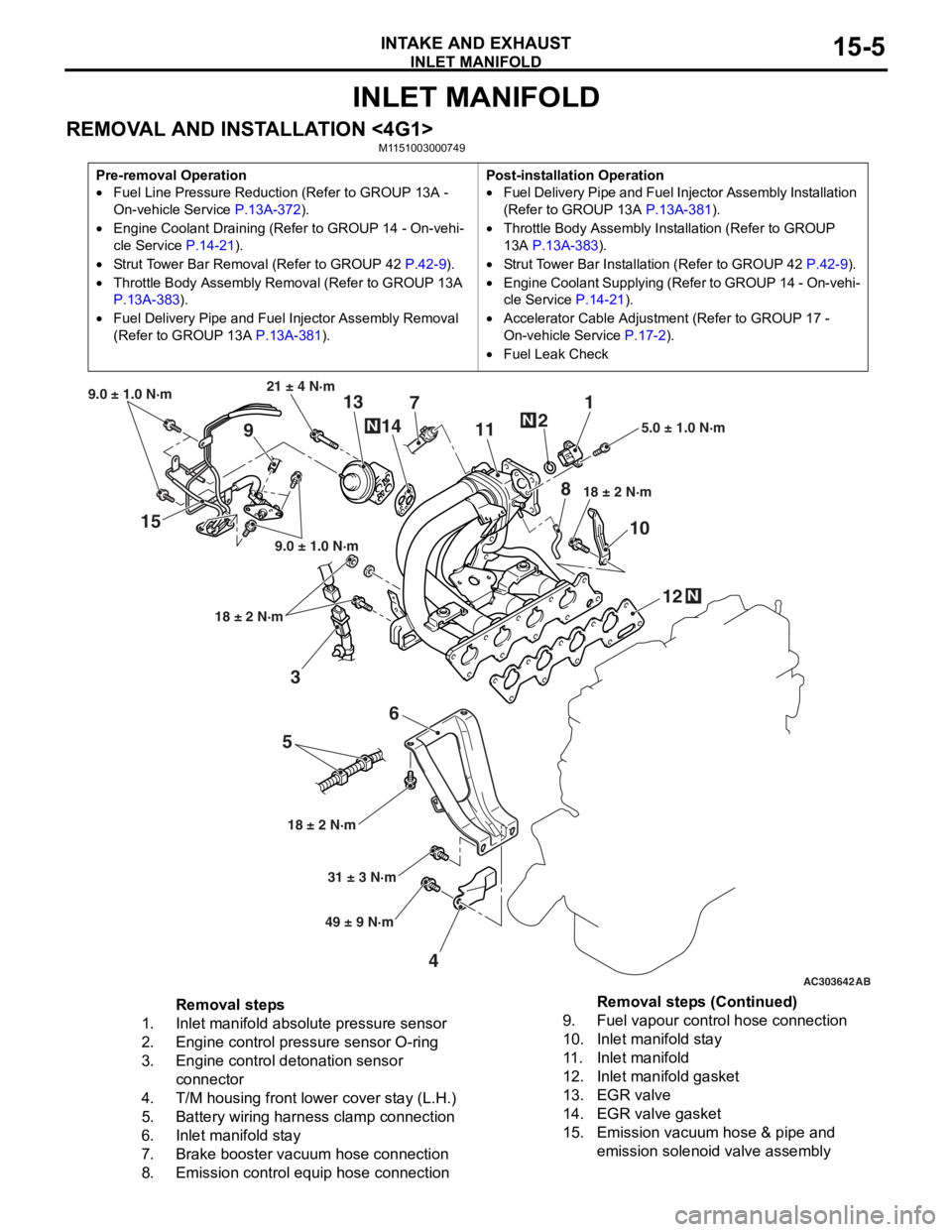
INLET MANIFOLD
INTAKE AND EXHAUST15-5
INLET MANIFOLD
REMOVAL AND INSTALLATION <4G1>M1151003000749
Pre-removal Operation
•Fuel Line Pressure Reduction (Refer to GROUP 13A -
On-vehicle Service
P.13A-372).
•Engine Coolant Draining (Refer to GROUP 14 - On-vehi-
cle Service P.14-21).
•Strut Tower Bar Removal (Refer to GROUP 42 P.42-9).
•Throttle Body Assembly Re moval (Refer to GROUP 13A
P.13A-383).
•Fuel Delivery Pipe and Fuel Injector Assembly Removal
(Refer to GROUP 13A
P.13A-381).
Post-installation Operation
•Fuel Delivery Pipe and Fuel Injector Assembly Installation
(Refer to GROUP 13A
P.13A-381).
•Throttle Body Assembly Inst allation (Refer to GROUP
13A
P.13A-383).
•Strut Tower Bar Installati on (Refer to GROUP 42 P.42-9).
•Engine Coolant Supplying (Refer to GROUP 14 - On-vehi-
cle Service P.14-21).
•Accelerator Cable Adjustment (Refer to GROUP 17 -
On-vehicle Service
P.17-2).
•Fuel Leak Check
AC303642AB
15
36
5
4 12
10
7
1
2
11
9 13
14
21 ± 4 N·m
9.0 ± 1.0 N·m
9.0 ± 1.0 N·m
18 ± 2 N·m
18 ± 2 N·m 18 ± 2 N·m
5.0 ± 1.0 N·m
31 ± 3 N·m
49 ± 9 N·m
N
N
N
8
Removal steps
1.Inlet manifold absolute pressure sensor
2.Engine control pressure sensor O-ring
3.Engine control detonation sensor
connector
4.T/M housing front lower cover stay (L.H.)
5.Battery wiring harness clamp connection
6.Inlet manifold stay
7.Brake booster vacuum hose connection
8.Emission control equip hose connection
9.Fuel vapour control hose connection
10.Inlet manifold stay
11 .Inlet manifold
12.Inlet manifold gasket
13.EGR valve
14.EGR valve gasket
15.Emission vacuum hose & pipe and
emission solenoid valve assembly
Removal steps (Continued)
Page 56 of 800
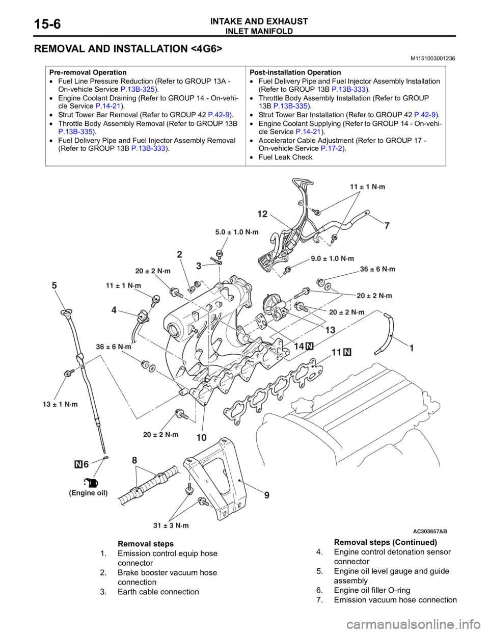
INLET MANIFOLD
INTAKE AND EXHAUST15-6
REMOVAL AND INSTALLATION <4G6>
M1151003001236
Pre-removal Operation
•Fuel Line Pressure Reduction (Refer to GROUP 13A -
On-vehicle Service P.13B-325).
•Engine Coolant Draining (Refer to GROUP 14 - On-vehi-cle Service P.14-21).
•Strut Tower Bar Removal (Refer to GROUP 42 P.42-9).
•Throttle Body Assembly Re moval (Refer to GROUP 13B
P.13B-335).
•Fuel Delivery Pipe and Fuel Injector Assembly Removal
(Refer to GROUP 13B
P.13B-333).
Post-installation Operation
•Fuel Delivery Pipe and Fuel Injector Assembly Installation
(Refer to GROUP 13B P.13B-333).
•Throttle Body Assembly Inst allation (Refer to GROUP
13B P.13B-335).
•Strut Tower Bar Installati on (Refer to GROUP 42 P.42-9).
•Engine Coolant Supplying (Refer to GROUP 14 - On-vehi-
cle Service P.14-21).
•Accelerator Cable Adjustment (Refer to GROUP 17 -
On-vehicle Service
P.17-2).
•Fuel Leak Check
AC303657
9.0 ± 1.0 N·m11 ± 1 N·m
20 ± 2 N·m 31 ± 3 N·m
36 ± 6 N·m
20 ± 2 N·m
20 ± 2 N·m
36 ± 6 N·m
20 ± 2 N·m
11
9
10
2
12
N14
13N
AB
5.0 ± 1.0 N·m
3
1
11 ± 1 N·m
4
N
13 ± 1 N·m
5
6
(Engine oil)
7
8
Removal steps
1.Emission control equip hose
connector
2.Brake booster vacuum hose
connection
3.Earth cable connection
4.Engine control detonation sensor
connector
5.Engine oil level gauge and guide
assembly
6.Engine oil filler O-ring
7.Emission vacuum hose connection
Removal steps (Continued)
Page 420 of 800
ENGINE AND TRANSMISSION
CONFIGURATION DIAGRAMS80-10
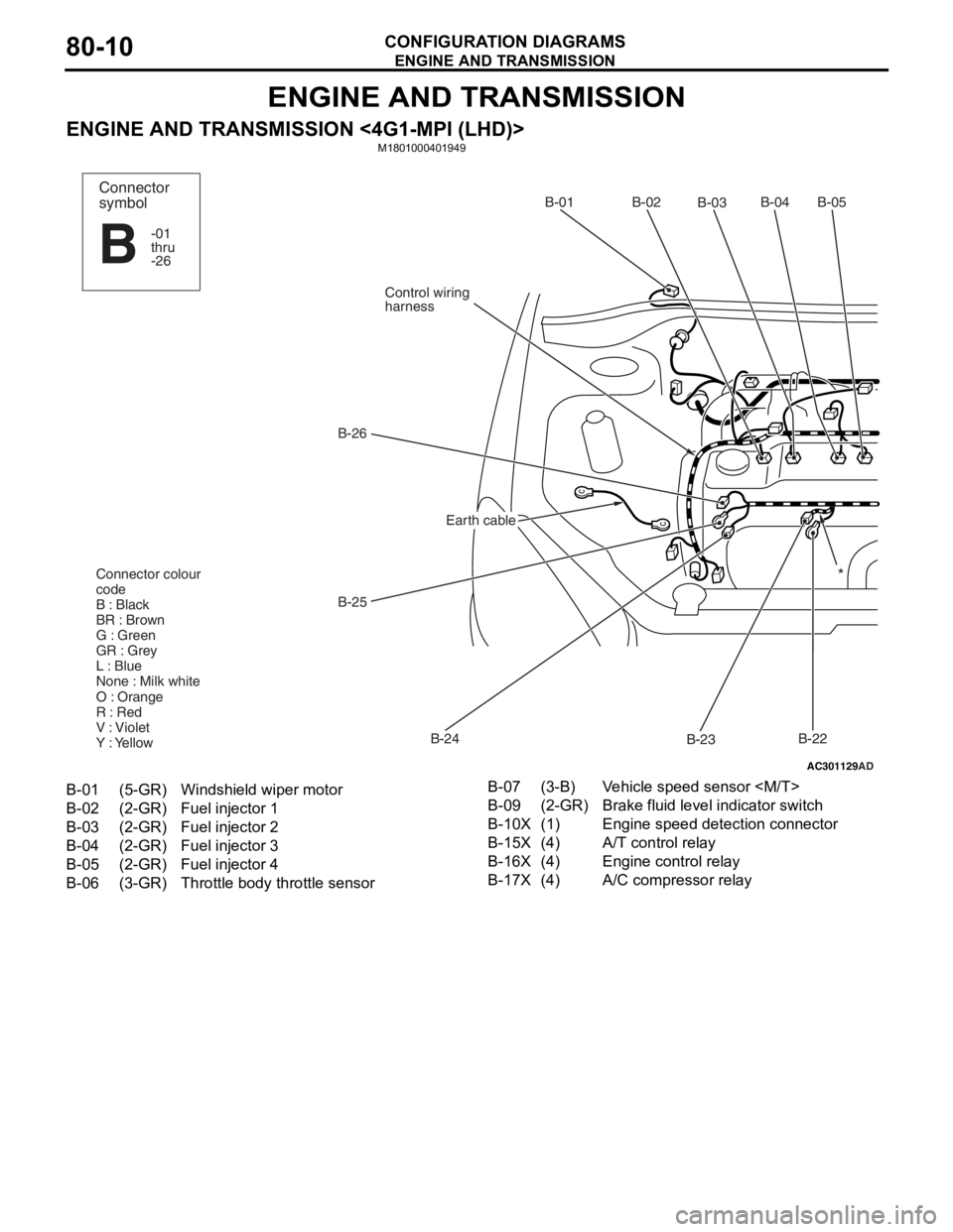
ENGINE AND TRANSMISSION
ENGINE AND TRANSMISSION <4G1-MPI (LHD)>M1801000401949
AC301129
AD
B-02
B-03B-04B-05
B-22
B-23
B-24
B-25
B-26
Control wiring
harnessB-01
Connector colour
code
B : Black
BR : Brown
G : Green
GR : Grey
L : Blue
None : Milk white
O : Orange
R : Red
V : Violet
Y : Yellow*
Connector
symbol
-01
thru
-26
B
Earth cable
B-01(5-GR)Windshield wiper motor
B-02(2-GR)Fuel injector 1
B-03(2-GR)Fuel injector 2
B-04(2-GR)Fuel injector 3
B-05(2-GR)Fuel injector 4
B-06(3-GR)Throttle body throttle sensor
B-07(3-B)Vehicle speed sensor
B-09(2-GR)Brake fluid level indicator switch
B-10X(1)Engine speed detection connector
B-15X(4)A/T control relay
B-16X(4)Engine control relay
B-17X(4)A/C compressor relay
Page 424 of 800
ENGINE AND TRANSMISSION
CONFIGURATION DIAGRAMS80-14
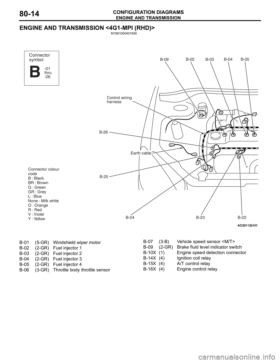
ENGINE AND TRANSMISSION <4G1-MPI (RHD)>
M1801000401950
AC301132AD
B-02
B-03B-04 B-05
B-22
B-23
B-24
B-25
B-26
Control wiring
harnessB-09
Connector colour
code
B : Black
BR : Brown
G : Green
GR : Grey
L : Blue
None : Milk white
O : Orange
R : Red
V : Violet
Y : Yellow*
Connector
symbol
-01
thru
-26
B
Earth cable
B-01(5-GR)Windshield wiper motor
B-02(2-GR)Fuel injector 1
B-03(2-GR)Fuel injector 2
B-04(2-GR)Fuel injector 3
B-05(2-GR)Fuel injector 4
B-06(3-GR)Throttle body throttle sensor
B-07(3-B)Vehicle speed sensor
B-09(2-GR)Brake fluid level indicator switch
B-10X(1)Engine speed detection connector
B-14X(4)Ignition coil relay
B-15X(4)A/T control relay
B-16X(4)Engine control relay
Page 428 of 800
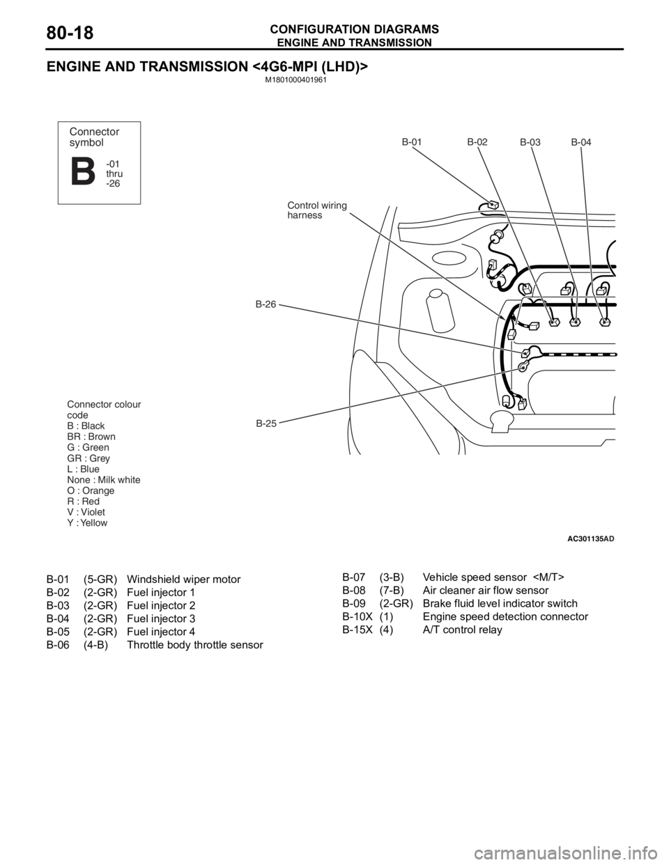
ENGINE AND TRANSMISSION
CONFIGURATION DIAGRAMS80-18
ENGINE AND TRANSMISSION <4G6-MPI (LHD)>
M1801000401961
AC301135AD
B-02
B-03B-04
B-25
B-26
Control wiring
harnessB-01
Connector colour
code
B : Black
BR : Brown
G : Green
GR : Grey
L : Blue
None : Milk white
O : Orange
R : Red
V : Violet
Y : YellowConnector
symbol
-01
thru
-26
B
B-01(5-GR)Windshield wiper motor
B-02(2-GR)Fuel injector 1
B-03(2-GR)Fuel injector 2
B-04(2-GR)Fuel injector 3
B-05(2-GR)Fuel injector 4
B-06(4-B)Throttle body throttle sensor
B-07(3-B)Vehicle speed sensor
B-08(7-B)Air cleaner air flow sensor
B-09(2-GR)Brake fluid level indicator switch
B-10X(1)Engine speed detection connector
B-15X(4)A/T control relay
Page 432 of 800
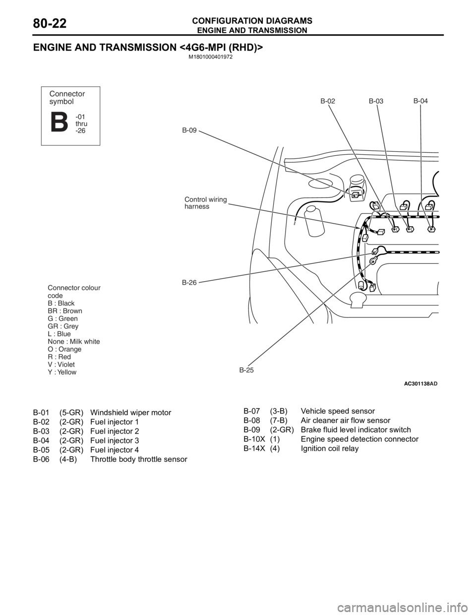
ENGINE AND TRANSMISSION
CONFIGURATION DIAGRAMS80-22
ENGINE AND TRANSMISSION <4G6-MPI (RHD)>
M1801000401972
AC301138
AD
B-02 B-03B-04
B-25
B-26
Control wiring
harness
B-09
Connector colour
code
B : Black
BR : Brown
G : Green
GR : Grey
L : Blue
None : Milk white
O : Orange
R : Red
V : Violet
Y : Yellow
Connector
symbol
-01
thru
-26
B
B-01(5-GR)Windshield wiper motor
B-02(2-GR)Fuel injector 1
B-03(2-GR)Fuel injector 2
B-04(2-GR)Fuel injector 3
B-05(2-GR)Fuel injector 4
B-06(4-B)Throttle body throttle sensor
B-07(3-B)Vehicle speed sensor
B-08(7-B)Air cleaner air flow sensor
B-09(2-GR)Brake fluid level indicator switch
B-10X(1)Engine speed detection connector
B-14X(4)Ignition coil relay
Page 482 of 800
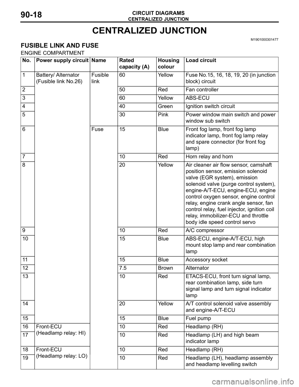
CENTRALIZED JUNCTION
CIRCUIT DIAGRAMS90-18
CENTRALIZED JUNCTION
M1901000301477
FUSIBLE LINK AND FUSE
ENGINE COMPARTMENT
No.Power supply circuitNameRated
capacity (A)Housing
colourLoad circuit
1Battery/ Alternator
(Fusible link No.26)Fusible
link60YellowFuse No.15, 16, 18, 19, 20 (in junction
block) circuit
250RedFan controller
360YellowABS-ECU
440GreenIgnition switch circuit
530PinkPower window main switch and power
window sub switch
6Fuse15BlueFront fog lamp, front fog lamp
indicator lamp, front fog lamp relay
and spare connector (for front fog
lamp)
710RedHorn relay and horn
820YellowAir cleaner air flow sensor, camshaft
position sensor, emission solenoid
valve (EGR system), emission
solenoid valve (purge control system),
engine-A/T-ECU, engine-ECU, engine
control oxygen sensor, engine control
relay, engine crank angle sensor, fan
control relay, fuel injector, ignition coil
relay, immobilizer-ECU and throttle
body idle speed control servo
910RedA/C compressor
1015BlueABS-ECU, engine-A/T-ECU, high
mount stop lamp and rear combination
lamp
1115BlueAccessory socket
127.5BrownAlternator
1310RedETACS-ECU, front turn signal lamp,
rear combination lamp, side turn
signal lamp and turn signal indicator
lamp
1420YellowA/T control solenoid valve assembly
and engine-A/T-ECU
1515BlueFuel pump
16Front-ECU
(Headlamp relay: HI)10RedHeadlamp (RH)
1710RedHeadlamp (LH) and high beam
indicator lamp
18Front-ECU
(Headlamp relay: LO)10RedHeadlamp (RH)
1910RedHeadlamp (LH), headlamp assembly
and headlamp levelling switch
Page 514 of 800
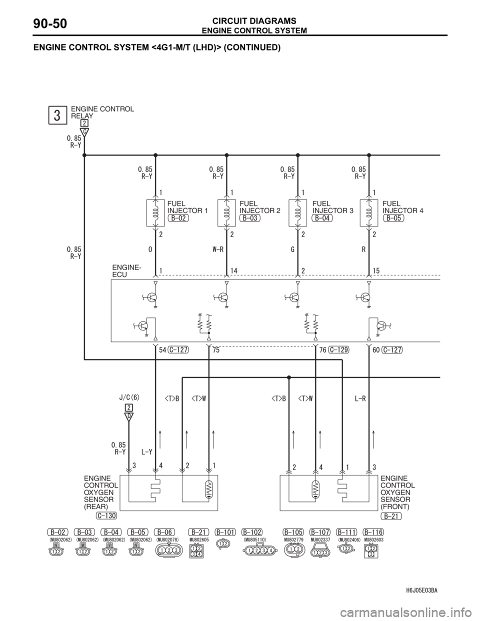
ENGINE CONTROL SYSTEM
CIRCUIT DIAGRAMS90-50
ENGINE CONTROL SYSTEM <4G1-M/T (LHD)> (CONTINUED)
ENGINE CONTROL
RELAY
FUEL
INJECTOR 1FUEL
INJECTOR 2FUEL
INJECTOR 3FUEL
INJECTOR 4
ENGINE-
ECU
ENGINE
CONTROL
OXYGEN
SENSOR
(REAR)ENGINE
CONTROL
OXYGEN
SENSOR
(FRONT)
Page 520 of 800
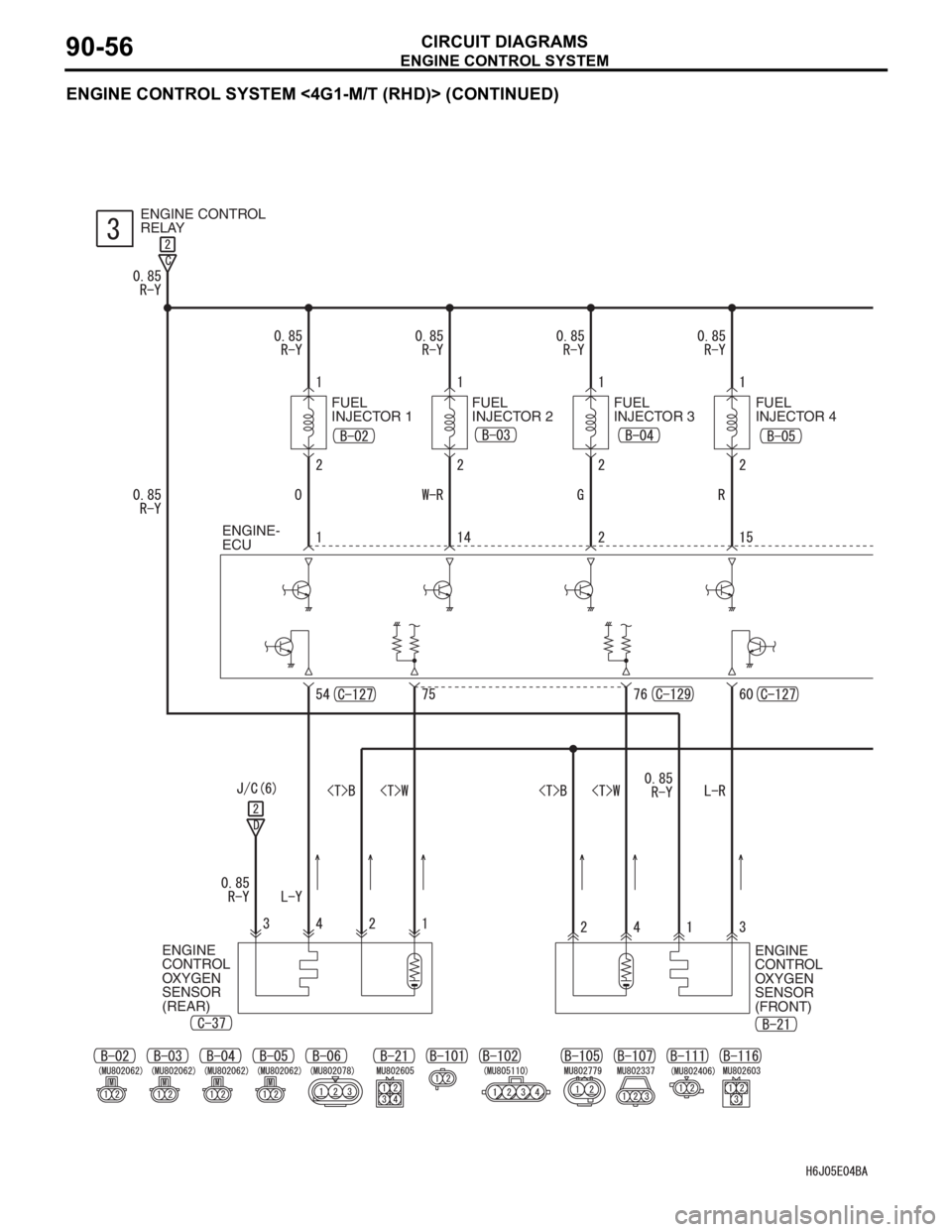
ENGINE CONTROL SYSTEM
CIRCUIT DIAGRAMS90-56
ENGINE CONTROL SYSTEM <4G1-M/T (RHD)> (CONTINUED)
ENGINE CONTROL
RELAY
FUEL
INJECTOR 1FUEL
INJECTOR 2FUEL
INJECTOR 3FUEL
INJECTOR 4
ENGINE-
ECU
ENGINE
CONTROL
OXYGEN
SENSOR
(REAR)ENGINE
CONTROL
OXYGEN
SENSOR
(FRONT)
Page 526 of 800
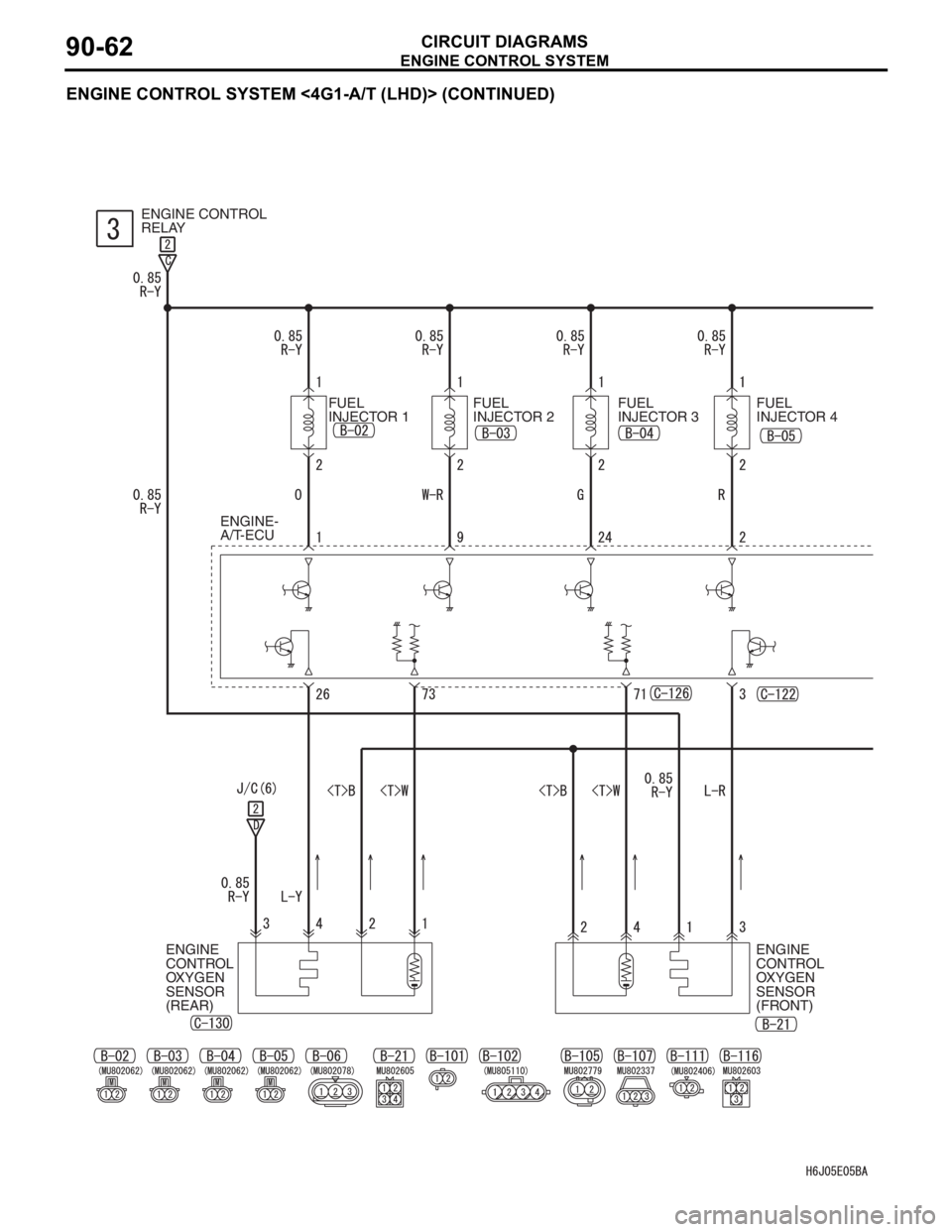
ENGINE CONTROL SYSTEM
CIRCUIT DIAGRAMS90-62
ENGINE CONTROL SYSTEM <4G1-A/T (LHD)> (CONTINUED)
ENGINE CONTROL
RELAY
ENGINE-
A/T-ECU
ENGINE
CONTROL
OXYGEN
SENSOR
(REAR)FUEL
INJECTOR 1FUEL
INJECTOR 2FUEL
INJECTOR 3FUEL
INJECTOR 4
ENGINE
CONTROL
OXYGEN
SENSOR
(FRONT)