Jack MITSUBISHI LANCER 2006 Workshop Manual
[x] Cancel search | Manufacturer: MITSUBISHI, Model Year: 2006, Model line: LANCER, Model: MITSUBISHI LANCER 2006Pages: 800, PDF Size: 45.03 MB
Page 35 of 800
ON-VEHICLE SERVICE
ENGINE COOLING14-21
ON-VEHICLE SERVICE
ENGINE COOLANT LEAK CHECKM1141001000300
WARNING
When pressure testing the cooling system,
slowly release cooling system pressure to
avoid getting burned by hot coolant.
CAUTION
•Be sure to completely clean away any mois-
ture from the places checked.
•When the tester is taken out, be careful not to
spill any coolant.
•
ACX01844
Cap adapter
Adapter
AC
Be careful when installing and removing the
tester and when testing not to deform the
filler neck of the radiator.
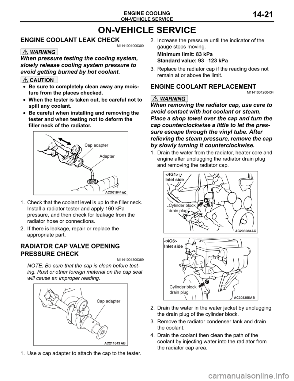
1. Check that the coolant leve l is up to the filler neck.
Install a radiator tester and apply 160 kPa
pressure, and then check for leakage from the
radiator hose or connections.
2. If there is leakage, repair or replace the
appropriate part.
RADIATOR CAP VALVE OPENING
PRESSURE CHECK
M1141001300389
NOTE: Be sure that the cap is clean before test-
ing. Rust or other foreign material on the cap seal
will cause an improper reading.
AC211643AB
Cap adapter
1. Use a cap adapter to attach the cap to the tester.
2. Increase the pressure until the indicator of the gauge stops moving.
Minimum limit: 83 kPa
Standard value: 93 − 123 kPa
3. Replace the radiator cap if the reading does not remain at or above the limit.
ENGINE COOLANT REPLACEMENT
M1141001200434
WARNING
When removing the radiator cap, use care to
avoid contact with hot coolant or steam.
Place a shop towel over the cap and turn the
cap counterclockwise a little to let the pres
-
sure escape through the vinyl tube. After
relieving the steam pres sure, remove the cap
by slowly turning it counterclockwise.
1. Drain the water from the radiator, heater core and
engine after unplugging the radiator drain plug
and removing the radiator cap.
AC208283AC
Cylinder block
drain plug
<4G1>
Inlet side
AC303355
<4G6>
Inlet side
Cylinder block
drain plug
AB
2. Drain the water in the water jacket by unplugging the drain plug of the cylinder block.
3. Remove the radiator condenser tank and drain
the coolant.
4. Drain the coolant then clean the path of the coolant by injecting water into the radiator from
the radiator cap area.
Page 169 of 800
ON-VEHICLE SERVICE
WHEEL AND TYRE31-7
ON-VEHICLE SERVICE
TYRE INFLATION PRESSURE CHECKM1311000900312
NOTE: For information on tyre inflation pressure,
refer to the label attached to the centre pillar on the
driver's side.
TYRE WEAR CHECK
M1311001000334
Measure the tread depth of the tyres.
Minimum limit: 1.6 mm
If the remaining tread depth is less than the minimum
limit, replace the tyre.
NOTE: When the tread depth of the tyres is reduced
to 1.6 mm or less, wear indicators will appear.
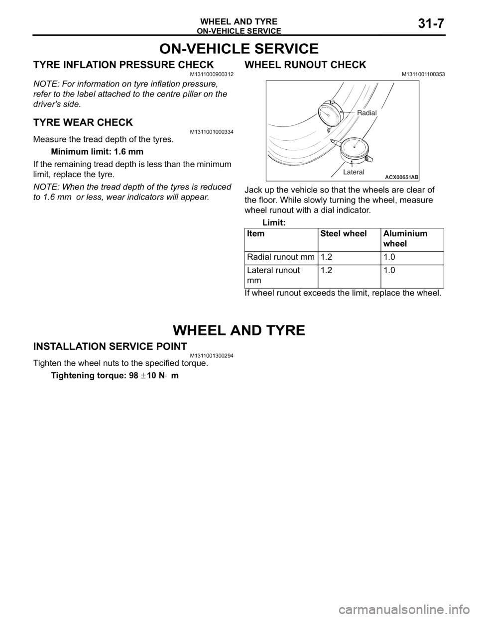
WHEEL RUNOUT CHECKM1311001100353
ACX00651 ABLateralRadial
Jack up
the vehicle so tha t the whe e ls are clear o f
the floor
. Wh ile slo w ly tur n ing the wheel, me asure
wh
eel ru nout wit h a dial indicator .
Limit:
ItemSt e e l wheelAluminium
whee
l
Radial runout mm1.21.0
Lateral runou t
mm1.21.0
If wheel runout exceeds the limit, rep l ace the whe e l.
WHEEL AND TYRE
INSTALLA T ION SER VICE POINTM131 1 0013 0029 4
Ti ghten the whee l nut s to the specified torq ue.
Ti ghte n ing torque: 98 ± 10 N⋅m
Page 181 of 800
Page 193 of 800
LOWER ARM
FRONT SUSPENSION33-11
LOWER ARM
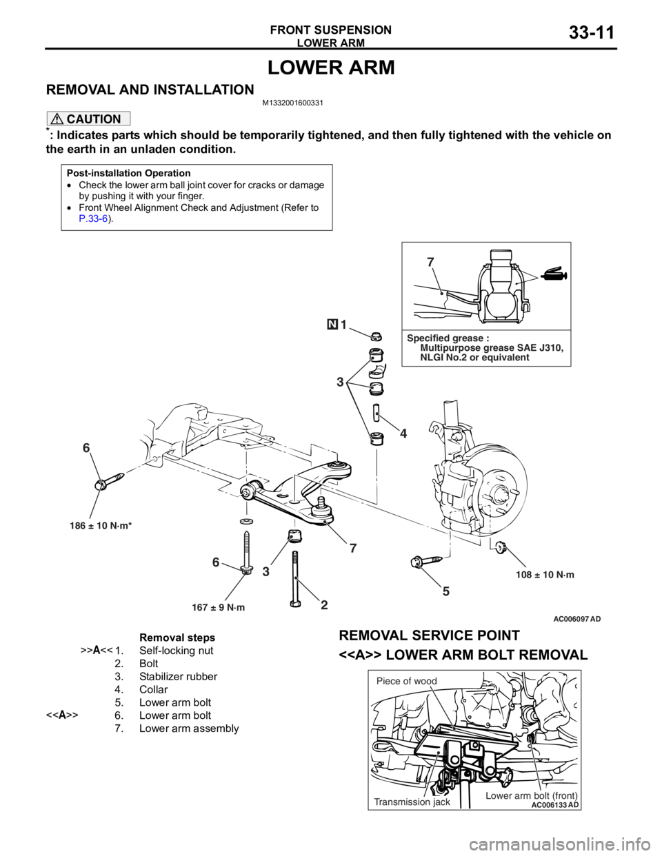
REMOVAL AND INSTALLATIONM1332001600331
CAUTION
*: Indicates parts which should be temporarily tightened, and then fully tightened with the vehicle on
the earth in an unladen condition.
Post-installation Operation
•Check the lower arm ball join t cover for cracks or damage
by pushing it with your finger.
•Front Wheel Alignment Check and Adjustment (Refer to
P.33-6).
AC006097 AD
7
1
3 4
5
108 ± 10 N·m
186 ± 10 N·m*
7
3
6
N
Specified grease :
Multipurpose grease SAE J310,
NLGI No.2 or equivalent
167 ± 9 N·m
6
2
Removal steps
>>A<<1.Self-locking nut
2.Bolt
3.Stabilizer rubber
4.Collar
5.Lower arm bolt
<>6.Lower arm bolt
7.Lower arm assembly
REMOVAL SERVICE POINT
<> LOWER ARM BOLT REMOVAL
AC006133
ADLower arm bolt (front)Transmission jackPiece of wood
Page 194 of 800
LOWER ARM
FRONT SUSPENSION33-12
As for the L.H. lower arm assembly, withdraw the
lower arm bolt (front) with the transmission lift up by
using a transmission jack.
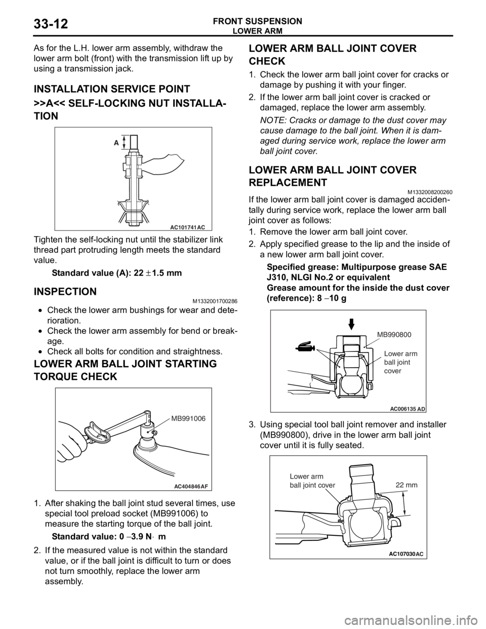
INSTALLATION SERVICE POINT
>>A<< SELF-LOCKING NUT INSTALLA-
TION
AC101741AC
A
T i ghten the self-locking nut un til t he st abilizer link
thread p
a rt protrud i ng length meet s the st a ndard
valu
e.
St andard va lue (A): 22 ± 1.5 m m
INSPECTION
M1332 0017 0028 6
•Check the lower arm bushing s for wear and det e-
riora t i o n.
•Check th e lo we r arm assemb ly for be nd or break-
age.
•Check all bo lt s for c ond ition and straightness.
LOWER ARM BALL JOINT ST ARTING
T
O RQUE CHECK
AC404846AF
MB991006
1.Af ter shaking the b a ll joint stud several times, use
special tool p r eloa d socke t (MB991 006) to
measure the st artin g torqu e of the ball joint.
St andard va lue: 0 − 3.9 N⋅m
2.If the measu r ed value is n o t within the st anda rd
value , or if the ba ll joint is dif f icu l t to t u rn or d oes
no t turn smo o thly , replace the lower a r m
asse mbly .
LOWER ARM BALL JOINT COVER
CHECK
1.Check t he lo we r arm b a ll joint co ver fo r cracks or
d a mag e by push i ng it with your finger .
2.If the lower arm ball joint co ver is cracked or
d a mag ed, rep l ace the lower arm assemb ly .
NOTE: Cracks or dama ge to t he dust co ver may
cause damage to the b a ll join t. When it is dam
-
aged du ring service wo rk, rep l ace the lower arm
b
a ll j o in t cover .
LOWER ARM BALL JOINT COVER
REPLACEMENT
M13320082 0026 0
If the lower arm ball jo int cove r is dama ged acciden-
ta lly durin g ser v ice work, repla c e th e lower arm b a ll
join
t cover as follows:
1.Remove the lower arm ball joint cover .
2.App l y specified grea se to the lip an d the inside of
a new lower arm ba ll join t cover .
Specified grease: Multipurpos e grease SAE
J310,
NLGI No.2 o r e quivale n t
Grease amount for the insi de the du st cove r
(re
f erence): 8
− 10 g
AC006135AD
MB990800
Lower arm
ball joint
cover
3. Using special tool ball joint remover and inst aller
(MB99080 0), drive in the lower arm ball jo int
cove r until it is fu lly se ated.
AC107030AC
22 mm
Lower arm
ball joint cover
Page 197 of 800
Removal steps
>>B<<1.Self-locking nut
2.Stabilizer rubber
3.Collar
>>A<<4.Stabilizer bar bracket
>>A<<5.Stabilizer bushing
6.Lower arm and knuckle
connection
<>7.Tie rod end and knuckle
connection
8.Engine rear roll stopper
bracket connecting bolt
9.Steering shaft cover
10.Steering gear and joint
connecting bolt
<>>>A<<11 .Stabilizer bar
STABILIZER BA R
FRONT SU SPENSION33-15
REMOVA L SER V ICE POINTS
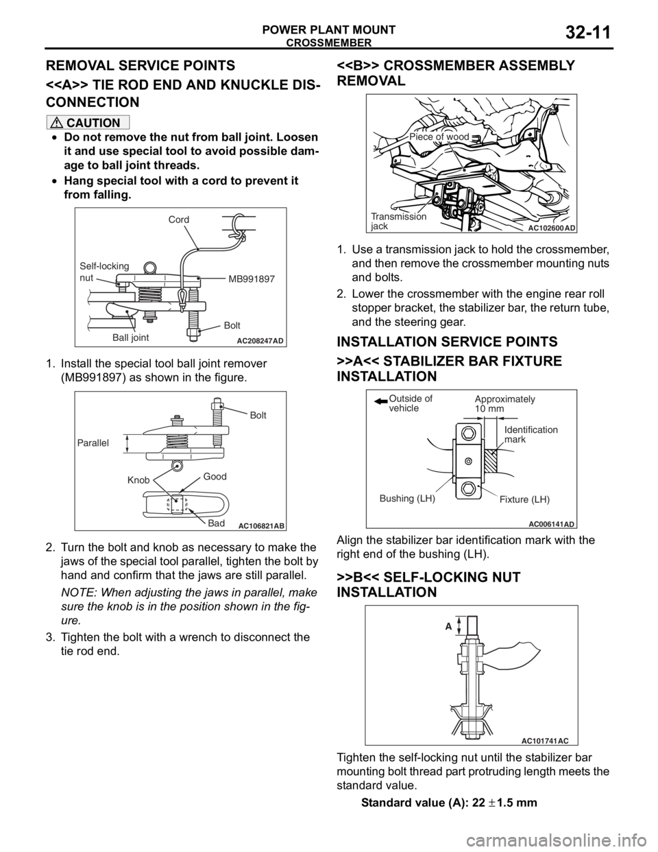
<> TIE ROD END AND KNUCKLE DIS-
CONNECTION
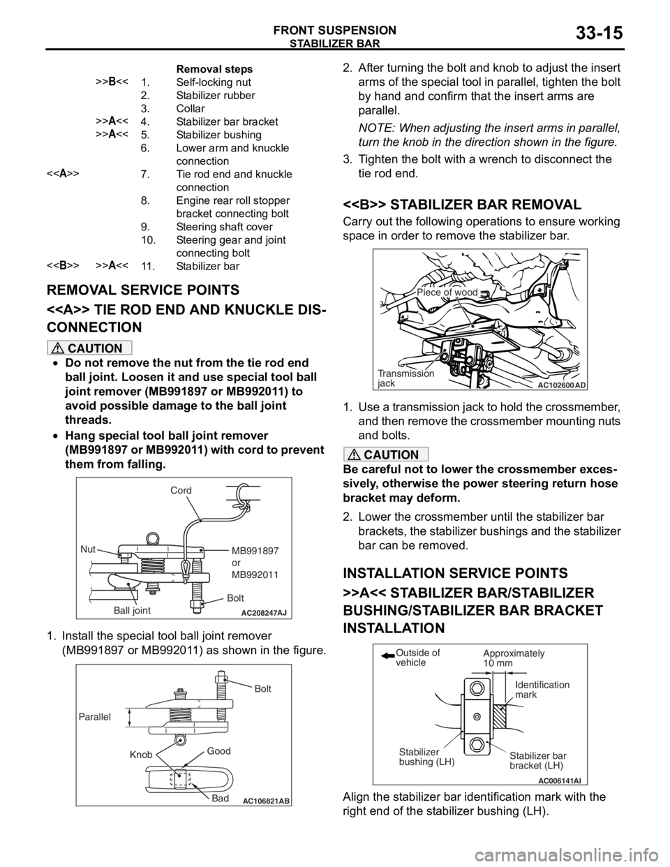
CAUTION
•Do not remove the nut from the tie rod end
ball joint. Loosen it and use special tool ball
joint remover (MB991897 or MB992011) to
avoid possible damage to the ball joint
threads.
•
AC208247AJ
Cord
BoltMB991897
or
MB992011
Nut
Ball joint
Hang special tool ball joint remover
(MB991897 or MB992011) with cord to prevent
them from falling.
1. Install the special tool ball joint remover (MB991897 or MB992011) as shown in the figure.
AC106821
Knob
Parallel
Bolt
Good Bad
AB
2. After turning the bolt and knob to adjust the insert arms of the special tool in parallel, tighten the bolt
by hand and confirm that the insert arms are
parallel.
NOTE: When adjusting the insert arms in parallel,
turn the knob in the direction shown in the figure.
3. Tighten the bolt with a wrench to disconnect the tie rod end.
<> STABILIZER BAR REMOVAL
Carry out the following operations to ensure working
space in order to remove the stabilizer bar.
AC102600 AD
Piece of wood
Transmission
jack
1. Use a transmission jack to hold the crossmember,
and then remove the crossmember mounting nuts
and bolts.
CAUTION
Be careful not to lower the crossmember exces-
sively, otherwise the power steering return hose
bracket may deform.
2. Lower the crossmember until the stabilizer bar
brackets, the stabilizer bush ings and the stabilizer
bar can be removed.
INSTALLATION SERVICE POINTS
>>A<< STABILIZER BAR/STABILIZER
BUSHING/STABILIZ ER BAR BRACKET
INSTALLATION
AC006141 AI
Stabilizer bar
bracket (LH)
Outside of
vehicle
Stabilizer
bushing (LH) Approximately
10 mm
Identification
mark
Align the stabilizer bar iden
tification mark with the
right end of the stabilizer bushing (LH).
Page 207 of 800
Page 211 of 800
Page 213 of 800
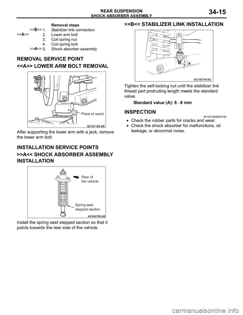
Removal steps
>>B<<1.Stabilizer link connection
<>2.Lower arm bolt
3.Coil spring nut
4.Coil spring bolt
>>A<<5.Shock absorber assembly
SHOCK ABSORBER ASSEMBLY
REAR SUSPENSION34-15
REMOVAL SERVICE POINT
<> LOWER ARM BOLT REMOVAL
AC107126AB
Piece of wood
After suppo rting the lo we r arm with a jack, remove
the lo
we r arm b o lt.
INSTALLA T ION SER VICE POINT S
>>A<< SHOCK ABSORBER ASSEMBL Y
INST
ALLA TION
AC304795 AB
Spring seat
stepped section
Rear of
the vehicle
Install the sprin g se at ste pped section so th at it
point
s towards the rea r side of th e ve hicle.
>>B<< STABILIZER LINK INST ALLA TION
AC103744
A
AC
Ti ghten the self-locking nut un til t he st ab ilizer link
thread
p a rt protrud i ng length mee t s the st a ndard
value.
St andard va lue (A): 6 − 8 mm
INSPECTIONM13410026 0015 0
•Check the rubbe r p a rt s for cracks a nd wear .
•Check the sho c k abso r ber for malfunct i ons, oil
le
akag e, or a bnormal no ise .
Page 266 of 800
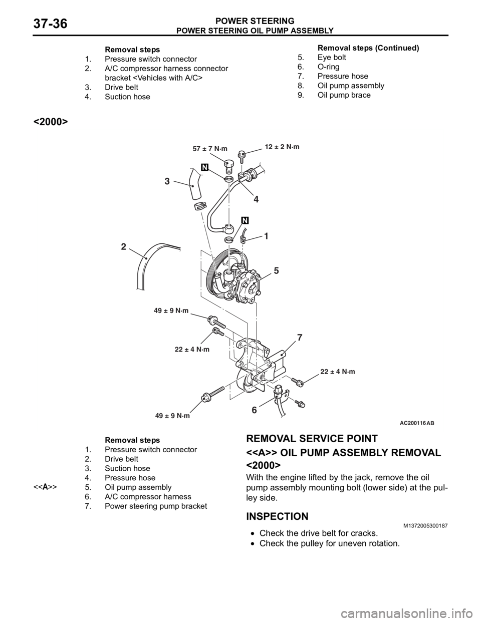
Removal steps
1.Pressure switch connector
2.A/C compressor harness connector
bracket
3.Drive belt
4.Suction hose
5.Eye bolt
6.O-ring
7.Pressure hose
8.Oil pump assembly
9.Oil pump brace
POWER STEERING OIL PUMP ASSEMBLY
POWER STEERING37-36
<2000>
AC200116AB
22 ± 4 N·m
12 ± 2 N·m
22 ± 4 N·m
49 ± 9 N·m 57 ± 7 N·m
1
5
4
3
6
2
7
49 ± 9 N·m
Removal steps
1.Pressure switch connector
2.Drive belt
3.Suction hose
4.Pressure hose
<>5.Oil pump assembly
6.A/C compressor harness
7.Power steering pump bracket
REMOVA L SER VICE POINT
<> OIL PUMP ASSEMBL Y REMOV A L
<2000>
With the eng ine lif t ed by the jack, remove the o il
pump
assembly mounting b o lt (lower side) a t the pul
-
ley side .
INSPECTIONM13720053 0018 7
•Check the drive belt for cracks.
•Check th e pulley for une ven r o t a tion.
Remova l st ep s ( C ont inu e d)