Panels MITSUBISHI LANCER 2006 Workshop Manual
[x] Cancel search | Manufacturer: MITSUBISHI, Model Year: 2006, Model line: LANCER, Model: MITSUBISHI LANCER 2006Pages: 800, PDF Size: 45.03 MB
Page 299 of 800
DOOR
BODY42-27
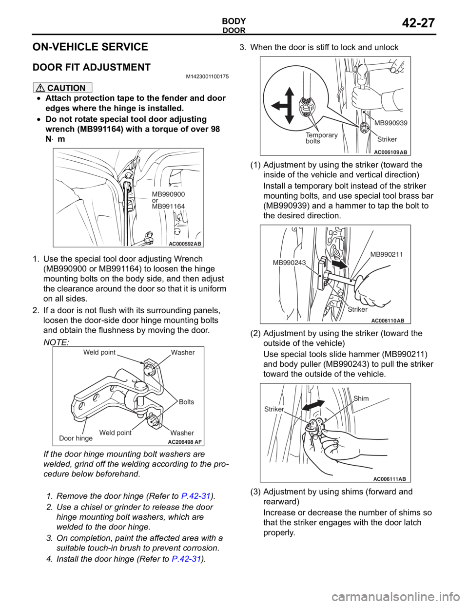
ON-VEHICLE SERVICE
DOOR FIT ADJUSTMENT
M1423001100175
CAUTION
•Attach protection tape to the fender and door
edges where the hinge is installed.
•Do not rotate special tool door adjusting
wrench (MB991164) with a torque of over 98
N
⋅m
AC000592
MB990900
or
MB991164
AB
1. Use the special tool door adjusting Wrench (MB990900 or MB991164) to loosen the hinge
mounting bolts on the body side, and then adjust
the clearance around the door so that it is uniform
on all sides.
2. If a door is not flush with its surrounding panels,
loosen the door-side d oor hinge mounting bolts
and obtain the flushness by moving the door.
NOTE:
AC206498
Washer Bolts
Washer
Door hinge
AF
Weld point
Weld point
If the door hinge mounting bolt washers are
welded, grind off the welding according to the pro
-
cedure below beforehand.
.
1. Remove the door hinge (Refer to P.42-31).
2. Use a chisel or grinder to release the door
hinge mounting bolt washers, which are
welded to the door hinge.
3. On completion, paint the affected area with a suitable touch-in brush to prevent corrosion.
4. Install the door hinge (Refer to P.42-31).
3. When the door is stiff to lock and unlock
AC006109AB
Temporary
bolts Striker
MB990939
(1) Adjustment by using the striker (toward the
inside of the vehicle and vertical direction)
Install a temporary bolt instead of the striker
mounting bolts, and use special tool brass bar
(MB990939) and a hammer to tap the bolt to
the desired direction.
AC006110
Striker MB990211
MB990243
AB
(2) Adjustment by using the striker (toward the
outside of the vehicle)
Use special tools slide hammer (MB990211)
and body puller (MB990243) to pull the striker
toward the outside of the vehicle.
AC006111AB
Shim
Striker
(3) Adjustment by using shims (forward and rearward)
Increase or decrease the number of shims so
that the striker engages with the door latch
properly.
Page 314 of 800
TRUNK LID
BODY42-42
3. If there is a difference in height between the side outer panels and the side edges of the trunk lid
panel assembly, check the trunk lid hinges and, if
necessary, replace them
4. If the clearance around the trunk lid panel assembly is not uniform, and the trunk lid can be
locked and unlocked smoothly, make adjustments
to the trunk lid bumpers (refer to
P.42-42) and
trunk lid hinges (Refer to P.42-42).
5. If the locking and unlocking of the trunk lid still is difficult after making the above adjustments,
adjust the trunk lid striker (Refer to
P.42-42).
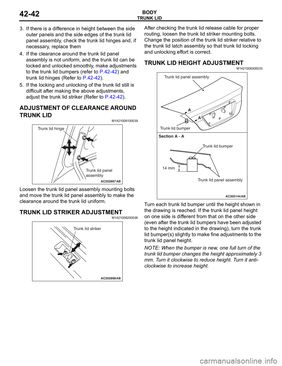
ADJUSTMENT OF CLEARANCE AROUND
TRUNK LID
M1421008100039
AC202897
Trunk lid panel
assembly
Trunk lid hinge
AB
Loosen the trunk lid p a nel a sse mbly mounting bolt s
and move
the trun k lid p anel assembly to make t he
clea
rance aroun d the t r unk lid u n iform.
TRUNK LID STRIKER ADJUSTMENT
M14210082 0003 6
AC202898
Trunk lid striker
AB
After checking the trunk lid relea s e cable for pro per
routin
g, lo osen the trun k lid striker mo untin g bolt s .
Ch
ange th e position of t he trunk lid st rike r relat i ve to
the trun
k lid la tch a s sembly so tha t trunk lid lockin g
and un
lockin g ef f o rt is corre ct.
TRUNK LID HEIGHT ADJUSTMENT
M14210083 0003 3
AC305144
Section A - A
Trunk lid bumper
Trunk lid panel assembly
A
A
Trunk lid bumper Trunk lid panel assembly
AB
14 mm
T
u rn each trun k lid bumper u n til the he ight shown in
the dra
w ing is reached. If the t r unk lid p a n e l he ight
on one
sid e is dif f erent from that on the oth e r side
(even
a f t e r th e t r un k lid bu mp ers have be en ad ju st ed
to the h
e igh t ind i ca ted in the dra w ing), tu rn the trunk
lid bumper(s)
slight ly to make fine adjustment s to the
trunk lid p
a nel h e ight .
NOTE: Whe n the b u mpe r is new , one full turn o f the
trunk lid bumper ch anges t he height appro x imately 3
mm.
T
u
rn it clockwise to r educe height. T u rn it anti
-
clockwise to increase height.