SAE MITSUBISHI LANCER 2006 Workshop Manual
[x] Cancel search | Manufacturer: MITSUBISHI, Model Year: 2006, Model line: LANCER, Model: MITSUBISHI LANCER 2006Pages: 800, PDF Size: 45.03 MB
Page 185 of 800
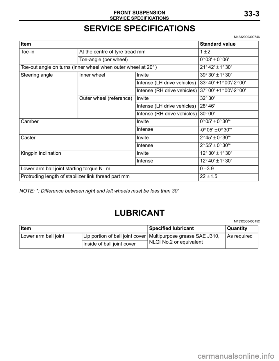
SERVICE SPECIFICATIONS
FRONT SUSPENSION33-3
SERVICE SPECIFICATIONS
M1332000300746
ItemStandard value
Toe-inAt the centre of tyre tread mm1 ± 2
Toe-angle (per wheel)0°03' ± 0°06'
Toe-out angle on turns (inner wheel when outer wheel at 20°)21°42' ± 1°30'
Steering angleInner wheelInvite39°30' ± 1°30'
Intense (LH drive vehicles)33°40' +1°00'/−2°00'
Intense (RH drive vehicles)37°00' +1°00'/−2°00'
Outer wheel (reference)Invite32°30'
Intense (LH drive vehicles)28°46'
Intense (RH drive vehicles)30°00'
CamberInvite0°05' ± 0°30'*
Intense−0°05' ± 0°30'*
CasterInvite2°45' ± 0°30'*
Intense2°55' ± 0°30'*
Kingpin inclinationInvite12°30' ± 1°30'
Intense12°40' ± 1°30'
Lower arm ball joint starting torque N⋅m0 − 3.9
Protruding length of stabilizer link thread part mm22 ± 1.5
NOTE: *: Difference between right and left wheels must be less than 30'
LUBRICANT
M1332000400152
ItemSpecified lubricantQuantity
Lower arm ball jointLip portion of ball joint coverMultipurpose grease SAE J310,
NLGI No.2 or equivalentAs required
Inside of ball joint cover
Page 193 of 800
LOWER ARM
FRONT SUSPENSION33-11
LOWER ARM
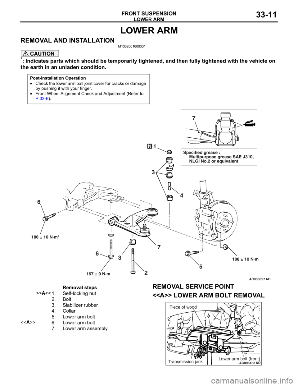
REMOVAL AND INSTALLATIONM1332001600331
CAUTION
*: Indicates parts which should be temporarily tightened, and then fully tightened with the vehicle on
the earth in an unladen condition.
Post-installation Operation
•Check the lower arm ball join t cover for cracks or damage
by pushing it with your finger.
•Front Wheel Alignment Check and Adjustment (Refer to
P.33-6).
AC006097 AD
7
1
3 4
5
108 ± 10 N·m
186 ± 10 N·m*
7
3
6
N
Specified grease :
Multipurpose grease SAE J310,
NLGI No.2 or equivalent
167 ± 9 N·m
6
2
Removal steps
>>A<<1.Self-locking nut
2.Bolt
3.Stabilizer rubber
4.Collar
5.Lower arm bolt
<>6.Lower arm bolt
7.Lower arm assembly
REMOVAL SERVICE POINT
<> LOWER ARM BOLT REMOVAL
AC006133
ADLower arm bolt (front)Transmission jackPiece of wood
Page 194 of 800
LOWER ARM
FRONT SUSPENSION33-12
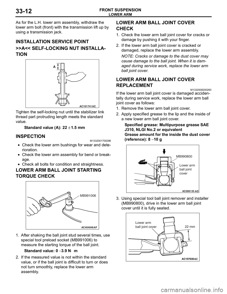
As for the L.H. lower arm assembly, withdraw the
lower arm bolt (front) with the transmission lift up by
using a transmission jack.
INSTALLATION SERVICE POINT
>>A<< SELF-LOCKING NUT INSTALLA-
TION
AC101741AC
A
T i ghten the self-locking nut un til t he st abilizer link
thread p
a rt protrud i ng length meet s the st a ndard
valu
e.
St andard va lue (A): 22 ± 1.5 m m
INSPECTION
M1332 0017 0028 6
•Check the lower arm bushing s for wear and det e-
riora t i o n.
•Check th e lo we r arm assemb ly for be nd or break-
age.
•Check all bo lt s for c ond ition and straightness.
LOWER ARM BALL JOINT ST ARTING
T
O RQUE CHECK
AC404846AF
MB991006
1.Af ter shaking the b a ll joint stud several times, use
special tool p r eloa d socke t (MB991 006) to
measure the st artin g torqu e of the ball joint.
St andard va lue: 0 − 3.9 N⋅m
2.If the measu r ed value is n o t within the st anda rd
value , or if the ba ll joint is dif f icu l t to t u rn or d oes
no t turn smo o thly , replace the lower a r m
asse mbly .
LOWER ARM BALL JOINT COVER
CHECK
1.Check t he lo we r arm b a ll joint co ver fo r cracks or
d a mag e by push i ng it with your finger .
2.If the lower arm ball joint co ver is cracked or
d a mag ed, rep l ace the lower arm assemb ly .
NOTE: Cracks or dama ge to t he dust co ver may
cause damage to the b a ll join t. When it is dam
-
aged du ring service wo rk, rep l ace the lower arm
b
a ll j o in t cover .
LOWER ARM BALL JOINT COVER
REPLACEMENT
M13320082 0026 0
If the lower arm ball jo int cove r is dama ged acciden-
ta lly durin g ser v ice work, repla c e th e lower arm b a ll
join
t cover as follows:
1.Remove the lower arm ball joint cover .
2.App l y specified grea se to the lip an d the inside of
a new lower arm ba ll join t cover .
Specified grease: Multipurpos e grease SAE
J310,
NLGI No.2 o r e quivale n t
Grease amount for the insi de the du st cove r
(re
f erence): 8
− 10 g
AC006135AD
MB990800
Lower arm
ball joint
cover
3. Using special tool ball joint remover and inst aller
(MB99080 0), drive in the lower arm ball jo int
cove r until it is fu lly se ated.
AC107030AC
22 mm
Lower arm
ball joint cover
Page 201 of 800
SERVICE SPECIFICATIONS
REAR SUSPENSION34-3
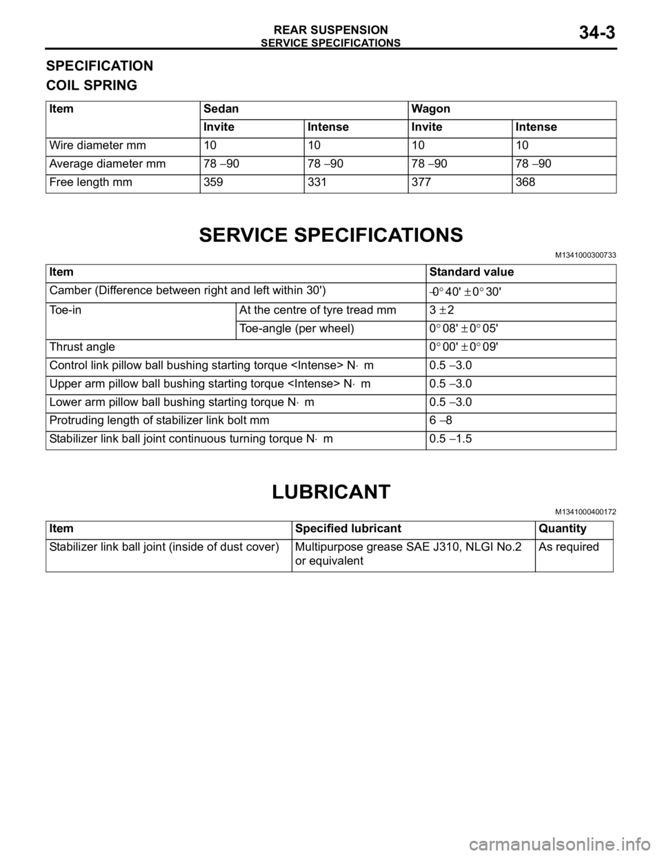
SPECIFICATION
COIL SPRING
ItemSedanWagon
InviteIntenseInviteIntense
Wire diameter mm10101010
Average diameter mm78 − 9078 − 9078 − 9078 − 90
Free length mm359331377368
SERVICE SPECIFICATIONS
M1341000300733
ItemStandard value
Camber (Difference between right and left within 30') −0°40' ± 0°30'
Toe-inAt the centre of tyre tread mm3 ± 2
Toe-angle (per wheel)0°08' ± 0°05'
Thrust angle0°00' ± 0°09'
Control link pillow ball bushing starting torque
Upper arm pillow ball bushing starting torque
Lower arm pillow ball bushing starting torque N⋅m0.5 − 3.0
Protruding length of stabilizer link bolt mm6 − 8
Stabilizer link ball joint continuous turning torque N⋅m0.5 − 1.5
LUBRICANT
M1341000400172
ItemSpecified lubricantQuantity
Stabilizer link ball joint (inside of dust cover)Multipurpose grease SAE J310, NLGI No.2
or equivalentAs required
Page 217 of 800
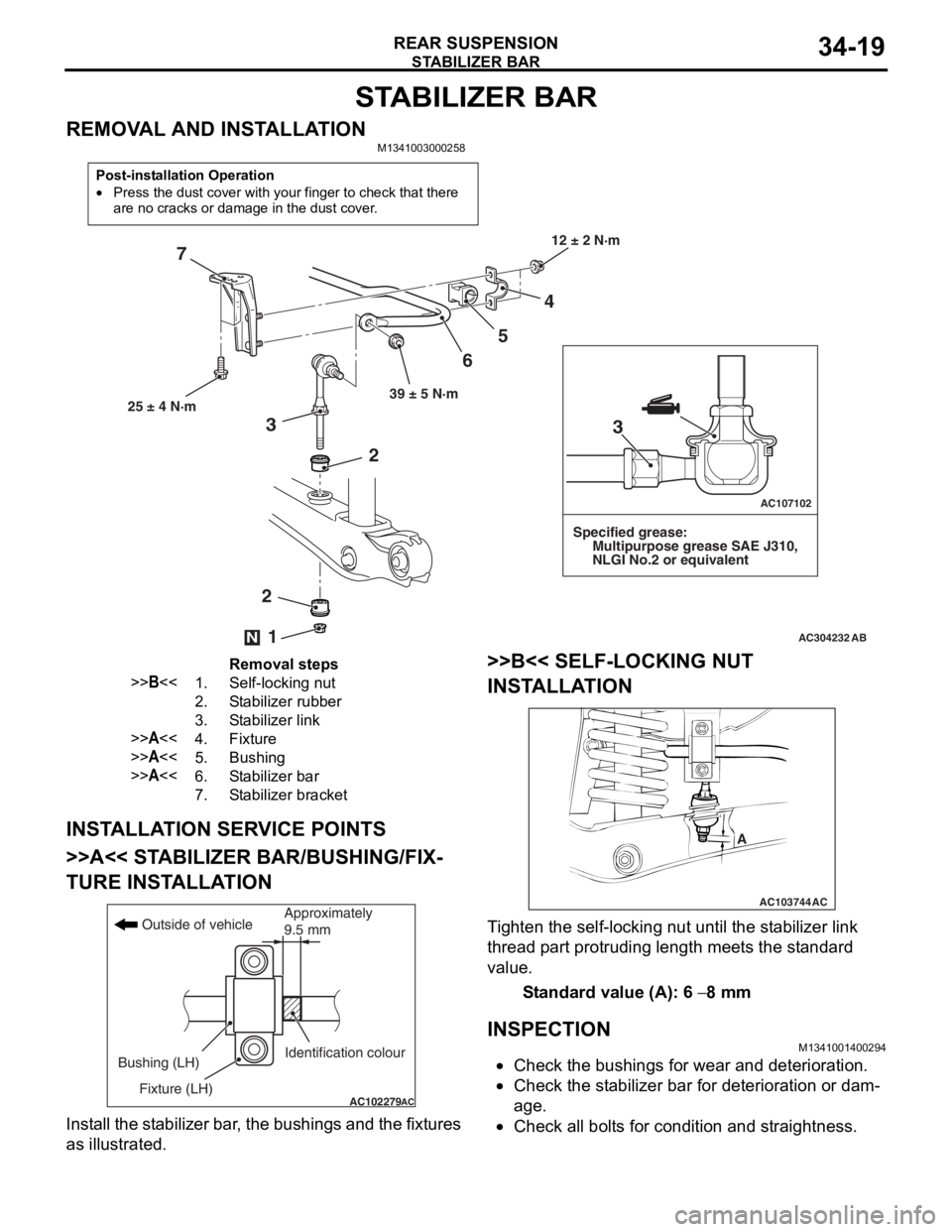
STABILIZER BAR
REAR SUSPENSION34-19
STABILIZER BAR
REMOVAL AND INSTALLATIONM1341003000258
Post-installation Operation
•Press the dust cover with your finger to check that there
are no cracks or damage in the dust cover.
AC304232
AC107102
AB
12 ± 2 N·m
39 ± 5 N·m
4
5
6
7
25 ± 4 N·m
Specified grease:
Multipurpose grease SAE J310,
NLGI No.2 or equivalent
2
2
3
1N
3
Removal steps
>>B<<1.Self-locking nut
2.Stabilizer rubber
3.Stabilizer link
>>A<<4.Fixture
>>A<<5.Bushing
>>A<<6.Stabilizer bar
7.Stabilizer bracket
INST ALLA T ION SER VICE POINT S
>>A<< STABILIZER BAR/BUSHING/FIX-
TURE INST ALLA TION
AC102279AC
Outside of vehicle
Bushing (LH) Fixture (LH) Identification colourApproximately
9.5 mm
Inst
all the st abilizer bar , th e bushings and the fixtures
as illustrate
d.
>>B<< SELF-LOCKING NUT
INST
ALLA TION
AC103744
A
AC
Ti ghten the self-locking nut un til t he st ab ilizer link
thread
p a rt protrud i ng length mee t s the st a ndard
value.
St andard va lue (A): 6 − 8 mm
INSPECTION
M13410014 0029 4
•Check the bushing s for wea r and d e terio r ation .
•Check the st abilizer bar for dete r iorat i on o r dam-
age.
•Check all bo lt s for cond itio n and straightness.
Page 218 of 800
STABILIZER BAR
REAR SUSPENSION34-20
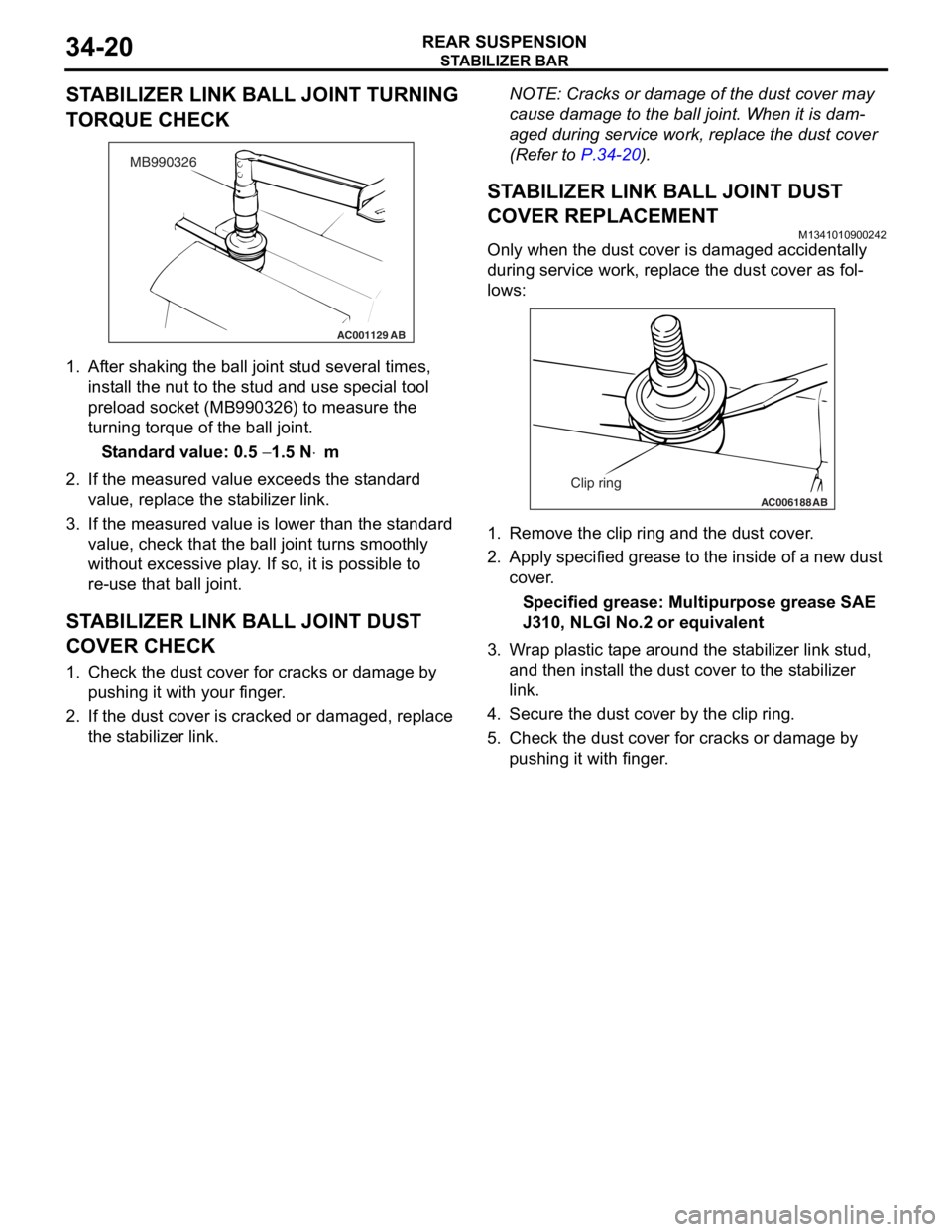
STABILIZER LINK BALL JOINT TURNING
TORQUE CHECK
AC001129
MB990326
AB
1.Af ter shaking th e ball jo int stud seve ral times,
inst all the n u t to t he st ud and use special tool
pre l oad socket (MB990 326) to measure th e
tu rning torque of the ball joint.
St andard va lue: 0.5 − 1.5 N⋅m
2.If the measu r ed value exceeds the st a ndard
value , replace the st ab ilizer link.
3.If the measu r ed value is lower tha n the st andard
value , che c k that th e ball jo int tu rns smoo thly
wit hout exce ssive play . I f so, it is possible to
re- u se t hat ball joint.
STABILIZER LINK BALL JOINT DUST
COVER CHECK
1. Check t he dust co ver fo r cracks or da mage by
pu shing it with your finger .
2.If the du st cover is cracked o r damaged, replace
th e st abilizer link.
NOTE: Cracks or dama ge of t he dust co ver may
cause damage to the b a ll join t. When it is dam
-
aged du ring service wo rk, rep l ace the d u st cover
(Refe
r to
P.34-2 0).
STABILIZER LINK BALL JOINT DUST
COVER REPLACEM
ENT
M13410109 0024 2
Only when the du st cover is d a ma ged accident ally
during
service work, repla c e th e dust cover as fol
-
lows:
AC006188 AB
Clip ring
1.Remove the clip ring and the dust cover .
2.App l y specified g r ease to t he insid e of a ne w dust
cov e r .
Specified grease: Multipurpos e grease SAE
J310,
NLGI No.2 o r e quivale n t
3.W r ap plast i c t ape aroun d the st a b ilize r lin k stud,
a nd then inst a ll th e dust co ver to the st a b ilizer
li nk.
4.Secure th e dust co ver by the clip rin g .
5.Check t he dust co ver f o r cracks or da mage by
p u shing it with finger .
Page 223 of 800
LUBRICANTS
PARKING BRAKES36-3
LUBRICANTS
M1361000400293
ItemSpecified lubricant
Rear brake shoe and backing plate contact surfaceBrake grease SAE J310, NLGI No.1
Rear brake shoe assembly
Rear brake shoe slack adjuster
ON-VEHIC LE SER VI CE
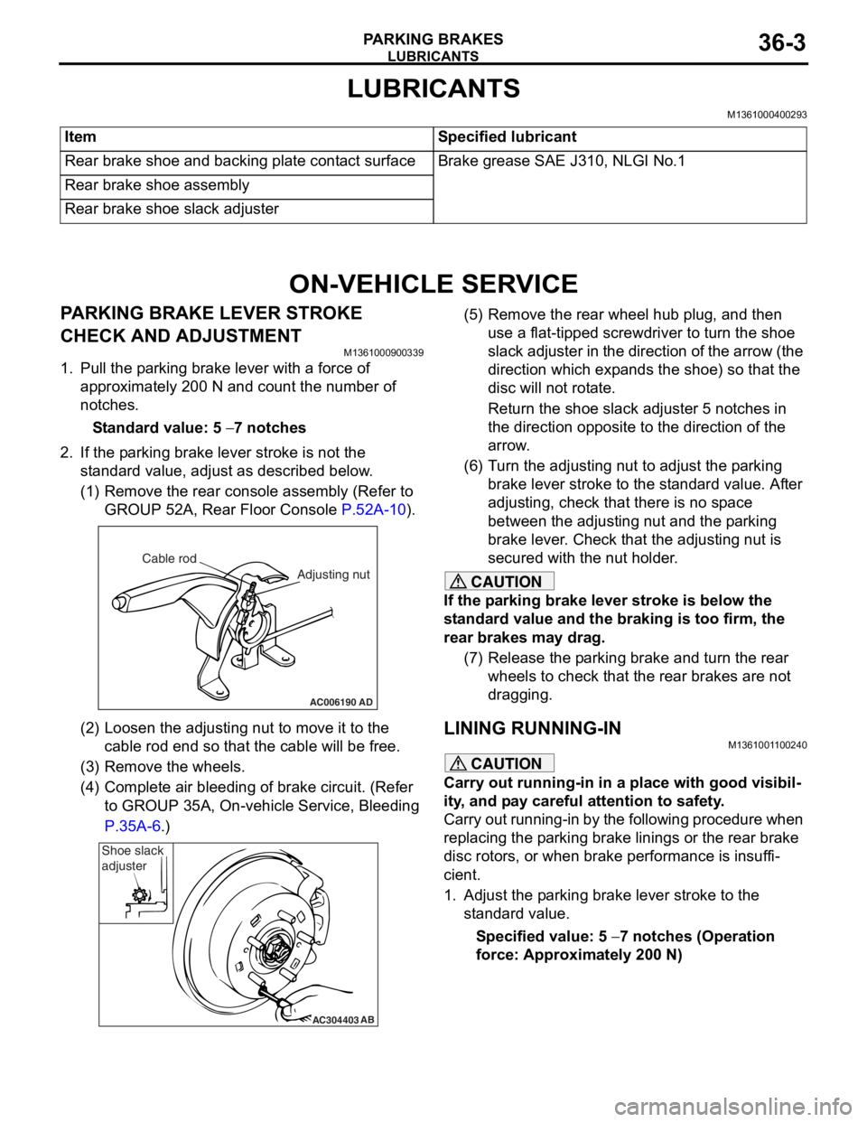
PARKING BRAKE LE VER STROKE
CHECK AND ADJUSTMENT
M13610009 0033 9
1.Pull the p a rkin g brake le ver wit h a force of
ap proxima t ely 200 N an d co unt the number of
no tche s.
St andard va lue: 5 − 7 notches
2.If the p a rking b r ake leve r stro ke is no t the
st a ndard valu e, adjust as de scribed below .
(1)R emove the rear console a sse mbly (Refer to
GROUP 5 2 A, Rear Floor Console
P.52A-10).
AC006190
Cable rod
Adjusting nut
AD
(2)Loosen th e adjusting nu t to move it to th e
cab l e rod end so tha t the cable will be fre e .
(3)R emove the wheels.
(4)C omplete a i r bleedin g of b r ake circuit. (Re f er
to GROUP 35A, On-ve h icle Service, Blee ding
P.35A-6.)
AC304403AB
Shoe slack
adjuster
(5
) R emove the rear whee l hub plug , and then
use a flat-tipped screwdriver to turn the shoe
slack ad juster in the direction of the arrow (the
dire ctio n which exp a nds the shoe) so that the
disc will no t rot a te.
Return the sh oe slack adjust e r 5 not ches in
the d
i rection opposite t o the d i rection of the
arrow
.
(6) T urn th e adjusting nut to adjust the p a rking
brake le ver stroke to the st anda rd value. Af ter
adjusting, check that there is n o sp ace
between the a d justing nut an d the p a rking
brake le ver . Che ck that th e adjusting nut is
secured with the nut ho lder .
CAUTION
If the parking brake lever stroke is below the
standard value and the braking is too firm, the
rear brakes may drag.
(7) Release the parking brake and turn the rear wheels to check that t he rear brakes are not
dragging.
LINING RUNNING-INM1361001100240
CAUTION
Carry out running-in in a place with good visibil-
ity, and pay careful attention to safety.
Carry out running-in by the following procedure when
replacing the parking brake linings or the rear brake
disc rotors, or when brake performance is insuffi
-
cient.
1. Adjust the parking brake lever stroke to the standard value.
Specified value: 5 − 7 notches (Operation
force: Approximately 200 N)
Page 227 of 800
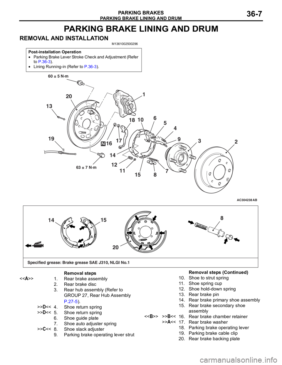
PARKING BRAKE LINING AND DRUM
PARKING BRAKES36-7
PARKING BRAKE LINING AND DRUM
REMOVAL AND INSTALLATIONM1361002500296
Post-installation Operation
•Parking Brake Lever Stroke Check and Adjustment (Refer
to
P.36-3).
•Lining Running-in (Refer to P.36-3).
AC304238
19
60 ± 5 N·m63 ± 7 N·m
AB
13 4
15 5
3
8 9
7 2
1
6
10
11
12 17
18
14
16
20
N
15
14
20 8
Specified grease: Brake grease SAE J310, NLGI No.1
Removal steps
<> 1. Rear brake assembly
2. Rear brake disc
3.Rear hub assembly (Refer to
GROUP 27, Rear Hub Assembly
P.27-5).
>>D<<4.Shoe return spring
>>D<<5. Shoe return spring
6. Shoe guide plate
7. Shoe auto adjuster spring
>>C<<8. Shoe slack adjuster
9. Parking brake operating lever strut
10. Shoe to strut spring
11 . Shoe spring cup
12. Shoe hold-down spring
13. Rear brake pin
14. Rear brake primary shoe assembly
15. Rear brake secondary shoe
assembly
<>>>B<<16. Rear brake chamber retainer
>>A<<17. Rear brake washer
18. Parking brake operating lever
19. Parking brake cable clip
20. Rear brake backing plate
Removal steps (Continued)
Page 237 of 800
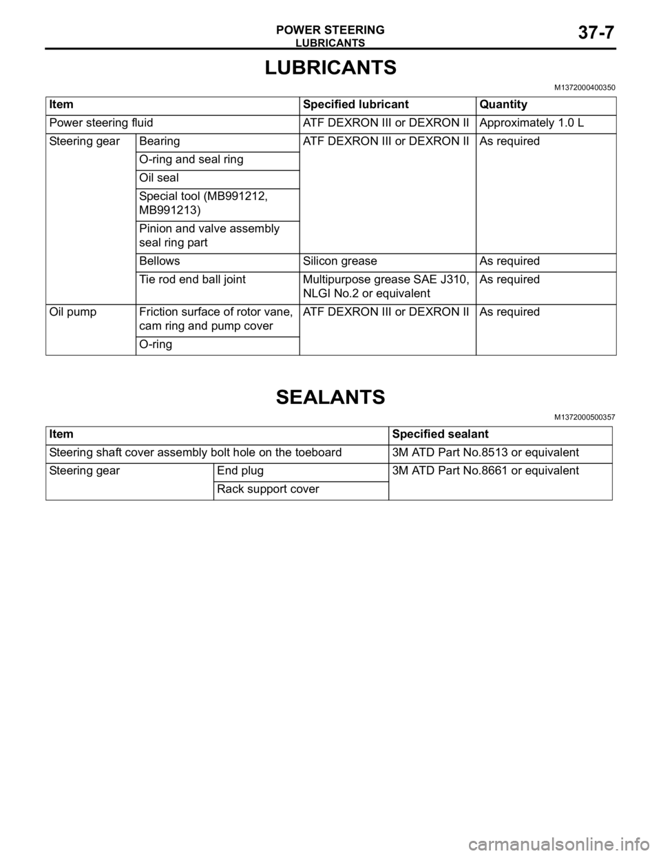
LUBRICANTS
POWER STEERING37-7
LUBRICANTS
M1372000400350
ItemSpecified lubricantQuantity
Power steering fluidATF DEXRON III or DEXRON IIApproximately 1.0 L
Steering gearBearingATF DEXRON III or DEXRON IIAs required
O-ring and seal ring
Oil seal
Special tool (MB991212,
MB991213)
Pinion and valve assembly
seal ring part
BellowsSilicon greaseAs required
Tie rod end ball jointMultipurpose grease SAE J310,
NLGI No.2 or equivalentAs required
Oil pumpFriction surface of rotor vane,
cam ring and pump coverATF DEXRON III or DEXRON IIAs required
O-ring
SEALANTS
M1372000500357
ItemSpecified sealant
Steering shaft cover assembly bolt hole on the toeboard3M ATD Part No.8513 or equivalent
Steering gearEnd plug3M ATD Part No.8661 or equivalent
Rack support cover
Page 258 of 800
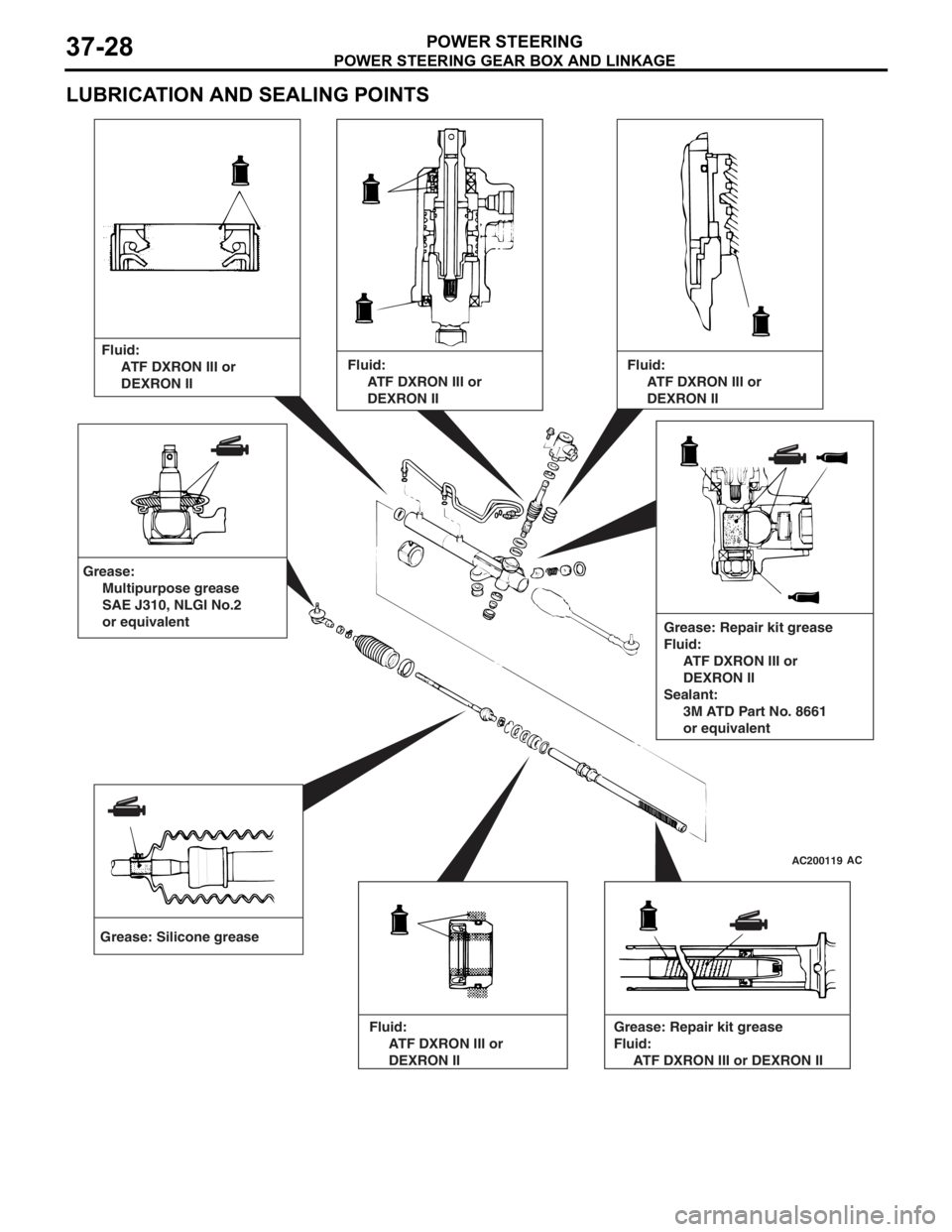
POWER STEERING GEAR BOX AND LINKAGE
POWER STEERING37-28
LUBRICATION AND SEALING POINTS
AC200119AC
Grease: Silicone greaseFluid:
ATF DXRON III or
DEXRON II
Grease: Repair kit grease
Fluid:
ATF DXRON III or
DEXRON II
Sealant:
3M ATD Part No. 8661
or equivalent
Grease:
Multipurpose grease
SAE J310, NLGI No.2
or equivalent
Fluid:
ATF DXRON III or
DEXRON II
Fluid:
ATF DXRON III or
DEXRON II
Fluid:
ATF DXRON III or
DEXRON II Grease: Repair kit grease
Fluid:
ATF DXRON III or DEXRON II