Trans MITSUBISHI LANCER 2006 Workshop Manual
[x] Cancel search | Manufacturer: MITSUBISHI, Model Year: 2006, Model line: LANCER, Model: MITSUBISHI LANCER 2006Pages: 800, PDF Size: 45.03 MB
Page 63 of 800
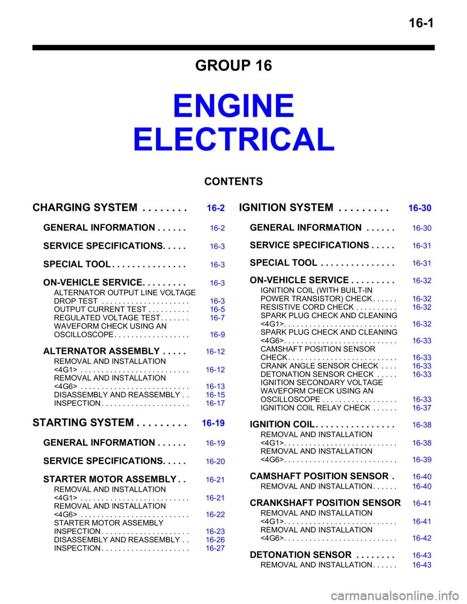
16-1
GROUP 16
ENGINE
ELECTRICAL
CONTENTS
CHARGING SYSTEM . . . . . . . .16-2
GENERAL INFORMATION . . . . . .16-2
SERVICE SPECIFICATIONS. . . . .16-3
SPECIAL TOOL . . . . . . . . . . . . . . .16-3
ON-VEHICLE SERVICE. . . . . . . . .16-3
ALTERNATOR OUTPUT LINE VOLTAGE
DROP TEST . . . . . . . . . . . . . . . . . . . . . 16-3
OUTPUT CURRENT TEST . . . . . . . . . . 16-5
REGULATED VOLTAGE TEST . . . . . . . 16-7
WAVEFORM CHECK USING AN
OSCILLOSCOPE . . . . . . . . . . . . . . . . . . 16-9
ALTERNATOR ASSEMB LY . . . . .16-12
REMOVAL AND INSTALLATION
<4G1> . . . . . . . . . . . . . . . . . . . . . . . . . . 16-12
REMOVAL AND INSTALLATION
<4G6> . . . . . . . . . . . . . . . . . . . . . . . . . . 16-13
DISASSEMBLY AND REASSEMBLY . . 16-15
INSPECTION . . . . . . . . . . . . . . . . . . . . . 16-17
STARTING SYSTEM . . . . . . . . .16-19
GENERAL INFORMATION . . . . . .16-19
SERVICE SPECIFICATIONS. . . . .16-20
STARTER MOTOR ASSEMBLY . .16-21
REMOVAL AND INSTALLATION
<4G1> . . . . . . . . . . . . . . . . . . . . . . . . . . 16-21
REMOVAL AND INSTALLATION
<4G6> . . . . . . . . . . . . . . . . . . . . . . . . . . 16-22
STARTER MOTOR ASSEMBLY
INSPECTION . . . . . . . . . . . . . . . . . . . . . 16-23
DISASSEMBLY AND REASSEMBLY . . 16-26
INSPECTION . . . . . . . . . . . . . . . . . . . . . 16-27
IGNITION SYSTEM . . . . . . . . . 16-30
GENERAL INFORMATION . . . . . .16-30
SERVICE SPECIFICATIONS . . . . .16-31
SPECIAL TOOL . . . . . . . . . . . . . . .16-31
ON-VEHICLE SERVICE . . . . . . . . .16-32
IGNITION COIL (WITH BUILT-IN
POWER TRANSISTOR) CHECK . . . . . . 16-32
RESISTIVE CORD CHECK . . . . . . . . . . 16-32
SPARK PLUG CHECK AND CLEANING
<4G1>. . . . . . . . . . . . . . . . . . . . . . . . . . . 16-32
SPARK PLUG CHECK AND CLEANING
<4G6>. . . . . . . . . . . . . . . . . . . . . . . . . . . 16-33
CAMSHAFT POSITION SENSOR
CHECK . . . . . . . . . . . . . . . . . . . . . . . . . . 16-33
CRANK ANGLE SENSOR CHECK . . . . 16-33
DETONATION SENSOR CHECK . . . . . 16-33
IGNITION SECONDARY VOLTAGE
WAVEFORM CHECK USING AN
OSCILLOSCOPE . . . . . . . . . . . . . . . . . . 16-33
IGNITION COIL RELAY CHECK . . . . . . 16-37
IGNITION COIL . . . . . . . . . . . . . . . .16-38
REMOVAL AND INSTALLATION
<4G1>. . . . . . . . . . . . . . . . . . . . . . . . . . . 16-38
REMOVAL AND INSTALLATION
<4G6>. . . . . . . . . . . . . . . . . . . . . . . . . . . 16-39
CAMSHAFT POSITION SENSOR .16-40
REMOVAL AND INSTALLATION . . . . . . 16-40
CRANKSHAFT POSITION SENSOR16-41
REMOVAL AND INSTALLATION
<4G1>. . . . . . . . . . . . . . . . . . . . . . . . . . . 16-41
REMOVAL AND INSTALLATION
<4G6>. . . . . . . . . . . . . . . . . . . . . . . . . . . 16-42
DETONATION SENSOR . . . . . . . .16-43
REMOVAL AND INSTALLATION . . . . . . 16-43
Page 76 of 800
AC303827
65
84
9
7
22 ± 4 N·m
23 ± 3 N·m
8.8 ± 1.0 N·m 44 ± 10 N·m
AB
13 ± 3 N·m
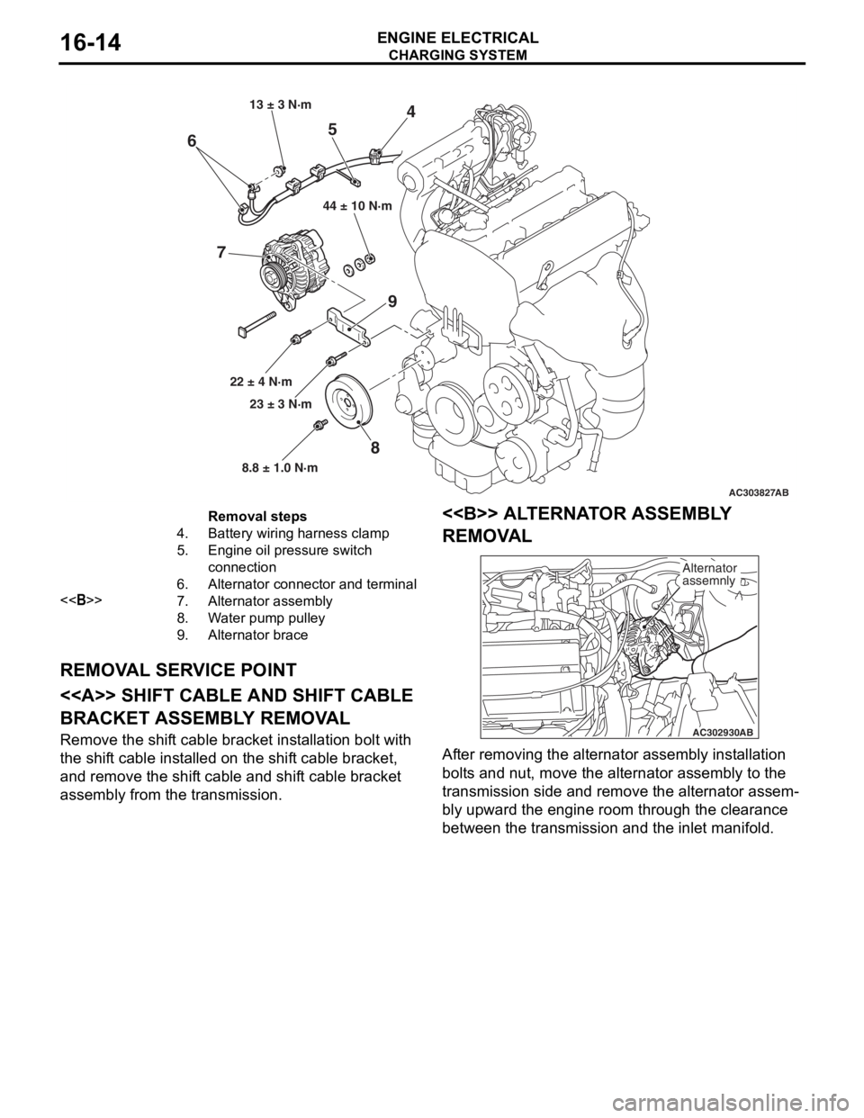
Removal steps
4.Battery wiring harness clamp
5.Engine oil pressure switch
connection
6.Alternator connector and terminal
<>7.Alternator assembly
8.Water pump pulley
9.Alternator brace
CHARGING SYSTEM
ENGINE ELECTRICAL16-14
REMOV
A L SER V ICE POINT
<> SHIFT CABLE AND SHIFT CABLE
BRACKET ASSEMBL
Y REMOV A L
Remove the shift cable bracket inst allation bolt with
the shif
t ca ble inst alled o n the shif t cable bracket,
and remove
the shif t cable and shif t cable bracket
assembly fro
m the transmission.
<> ALTERNA T O R ASSEMBL Y
REMOV
A L
AC302930 AB
Alternator
assemnly
Af
ter re moving the alternato r assembly inst allation
bolt
s a nd nu t, move the alte rnator a sse mbly to the
transmission side an
d remove the alternato r assem
-
bly upward the engine roo m thr ough th e clearan ce
between t
he tran smission and the inlet ma nifold.
Page 83 of 800
STARTING SYSTEM
ENGINE ELECTRICAL16-21
STARTER MOTOR ASSEMBLY
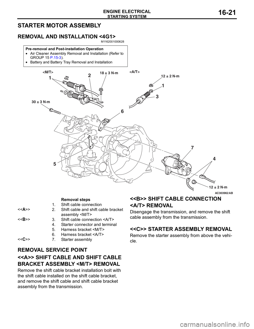
REMOVAL AND INSTALLATION <4G1>
M1162001000628
Pre-removal and Post-installation Operation
•Air Cleaner Assembly Removal and Installation (Refer to
GROUP 15 P.15-3).
•Battery and Battery Tray Removal and Installation
AC303962AB
11
2
3
5 6
74
30 ± 3 N·m 18 ± 3 N·m
12 ± 2 N·m
12 ± 2 N·m
Removal steps
1.Shift cable connection
<>2.Shift cable and shift cable bracket
assembly
<>3.Shift cable connection
4.Starter connector and terminal
5.Harness bracket
6.Harness bracket
<
REMOVA L SER V ICE POINT
<> SHIFT CABLE AND SHIFT CABLE
BRACKET ASSEMBL
Y
Remove the shift cable bracket inst allation bolt with
the shif
t ca ble inst alled o n the shif t cable bracket,
and remove
the shif t cable and shif t cable bracket
assembly fro
m the transmission.
<> SHIFT CABLE CONNECTION
REMOVA L
Disengage th e transmission, a nd remove the shif t
cable assembly from the tra
n smission .
<
Remove the st arter assembly from above the veh i-
cle.
Page 92 of 800
IGNITION SYSTEM
ENGINE ELECTRICAL16-30
IGNITION SYSTEM
GENERAL INFORMATIONM1163000100294
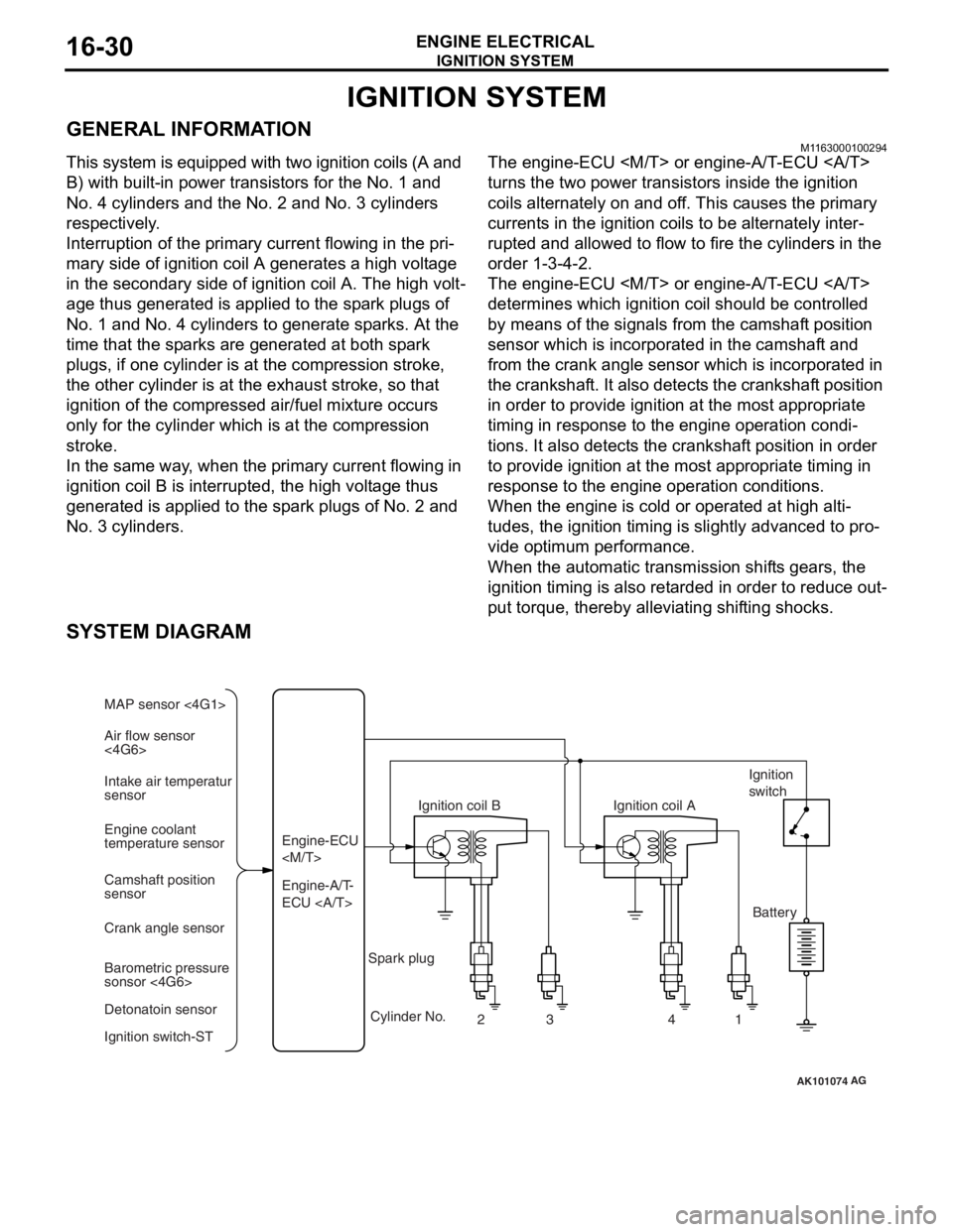
This system is equipped with two ignition coils (A and
B) with built-in power transistors for the No. 1 and
No. 4 cylinders and the No. 2 and No. 3 cylinders
respectively.
Interruption of the primary current flowing in the pri-
mary side of ignition coil A generates a high voltage
in the secondary side of ignition coil A. The high volt
-
age thus generated is applied to the spark plugs of
No. 1 and No. 4 cylinders to generate sparks. At the
time that the sparks are generated at both spark
plugs, if one cylinder is at the compression stroke,
the other cylinder is at the exhaust stroke, so that
ignition of the compressed air/fuel mixture occurs
only for the cylinder which is at the compression
stroke.
In the same way, when the primary current flowing in
ignition coil B is interrupted, the high voltage thus
generated is applied to the spark plugs of No. 2 and
No. 3 cylinders.
The engine-ECU
turns the two power transistors inside the ignition
coils alternately on and off. This causes the primary
currents in the ignition coils to be alternately inter
-
rupted and allowed to flow to fire the cylinders in the
order 1-3-4-2.
The engine-ECU
determines which ignition coil should be controlled
by means of the signals from the camshaft position
sensor which is incorporated in the camshaft and
from the crank angle sensor which is incorporated in
the crankshaft. It also detects the crankshaft position
in order to provide ignition at the most appropriate
timing in response to the engine operation condi
-
tions. It also detects the crankshaft position in order
to provide ignition at the most appropriate timing in
response to the engine operation conditions.
When the engine is cold or operated at high alti-
tudes, the ignition timing is slightly advanced to pro-
vide optimum performance.
When the automatic transmission shifts gears, the
ignition timing is also retarded in order to reduce out
-
put torque, thereby alleviating shifting shocks.
SYSTEM DIAGRAM
AK101074
Air flow sensor
<4G6> MAP sensor <4G1>
Intake air temperatur
sensor
Engine coolant
temperature sensor
Camshaft position
sensor
Crank angle sensor
Barometric pressure
sonsor <4G6>
Detonatoin sensor
Ignition switch-ST Engine-A/T-
ECU Engine-ECU
Ignition coil B
Cylinder No. 23 4
AG
1
Spark plug Ignition coil A
Ignition
switch
Battery
Page 94 of 800
IGNITION SYSTEM
ENGINE ELECTRICAL16-32
ON-VEHICLE SERVICE
IGNITION COIL (WITH BUILT-IN POWER
TRANSISTOR) CHECK
M1163001200324
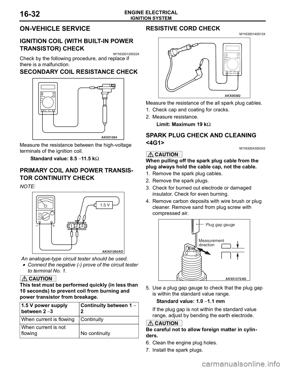
Check by the following procedure, and replace if
there is a malfunction.
SECONDARY COIL RESISTANCE CHECK
AKX01264
Measure the resist ance bet we en the high- volt ag e
terminals of th
e ign i tio n coil.
St andard va lue: 8.5 − 11 .5 kΩ
PRIM AR Y COIL AND POWER TRANSIS-
TO R CONTINUITY CHECK
NO TE: .•
AKX01265 AD
1.5 V
1 23
+
–
An analogue-t y pe circuit t e ster shou ld be use d .
•Connect the n egative (-) pro v e of the circuit t e ster
to t
e rminal No. 1.
CAUTION
This test must be performed quickly (in less than
10 seconds) to prevent coil from burning and
power transistor from breakage.
1.5 V power supply
between 2
− 3
Continuity between 1 −
2
When current is flowingContinuity
When current is not
flowing
No continuity
RESISTIVE CORD CHECK
M1163001400124
AKX00382
Measure the resistance of the all spark plug cables.
1. Check cap and coating for cracks.
2. Measure resistance.
Limit: Maximum 19 kΩ
SPARK PLUG CHECK AND CLEANING
<4G1>
M1163004300342
CAUTION
When pulling off the spark plug cable from the
plug always hold the cable cap, not the cable.
1. Remove the spark plug cables.
2. Remove the spark plugs.
3. Check for burned out electrode or damaged insulator. Check for even burning.
4. Remove carbon deposits with wire brush or plug cleaner. Remove sand from plug screw with
compressed air.
AKX01272 AG
Plug gap gauge
Measurement
direction
5. Use a plug gap gauge to check that the plug gap is within the standard value range.
Standard value: 1.0 − 1.1 mm
If the plug gap is not within the standard value
range, adjust by bending the earth electrode.
CAUTION
Be careful not to allow foreign matter in cylin-
ders.
6. Clean the engine plug holes.
7. Install the spark plugs.
Page 129 of 800
22-1
GROUP 22
MANUAL
TRANSMISSION
CONTENTS
MANUAL TRANSMISSION (FF) . . . . . . . . . . . . . . . . . . . . . . . . .22A
MANUAL TRANSMISSION OVERHAUL . . . . . . . . . . . . . . . . . .22B
Page 131 of 800
23-1
GROUP 23
AUTOM ATIC
TRANSMISSION
CONTENTS
AUTOMATIC TRANSMISSION (FF) . . . . . . . . . . . . . . . . . . . . . .23A
AUTOMATIC TRANSMISSION OVERHAUL . . . . . . . . . . . . . . .23B
Page 134 of 800
GENERAL INFORMATION
FRONT AXLE26-2
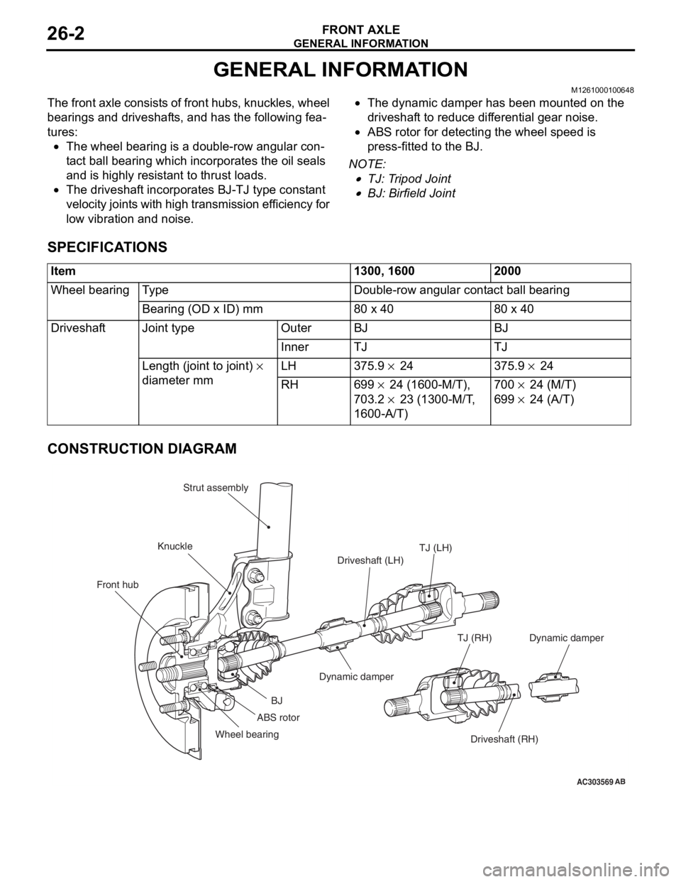
GENERAL INFORMATION
M1261000100648
The front axle consists of front hubs, knuckles, wheel
bearings and driveshafts, and has the following fea
-
tures:
•The wheel bearing is a double-row angular con-
tact ball bearing which incorporates the oil seals
and is highly resistant to thrust loads.
•The driveshaft incorporates BJ-TJ type constant
velocity joints with high transmission efficiency for
low vibration and noise.
•The dynamic damper has been mounted on the
driveshaft to reduce differential gear noise.
•ABS rotor for detecting the wheel speed is
press-fitted to the BJ.
NOTE: .
•TJ: Tripod Joint
•BJ: Birfield Joint
SPECIFICATIONS
Item1300, 16002000
Wheel bearingTy p eDouble-row angular contact ball bearing
Bearing (OD x ID) mm80 x 4080 x 40
DriveshaftJoint typeOuterBJBJ
InnerTJTJ
Length (joint to joint) ×
diameter mm LH 375.9 × 24 375.9 × 24
RH699 × 24 (1600-M/T),
703.2
× 23 (1300-M/T,
1600-A/T)
700 × 24 (M/T)
699 × 24 (A/T)
CONSTRUCTION DIAGRAM
AC303569
Front hub KnuckleStrut assembly
TJ (LH)
Driveshaft (LH)
Dynamic damper
BJ
Wheel bearing Driveshaft (RH)
TJ (RH)
AB
ABS rotor
Dynamic damper
Page 137 of 800
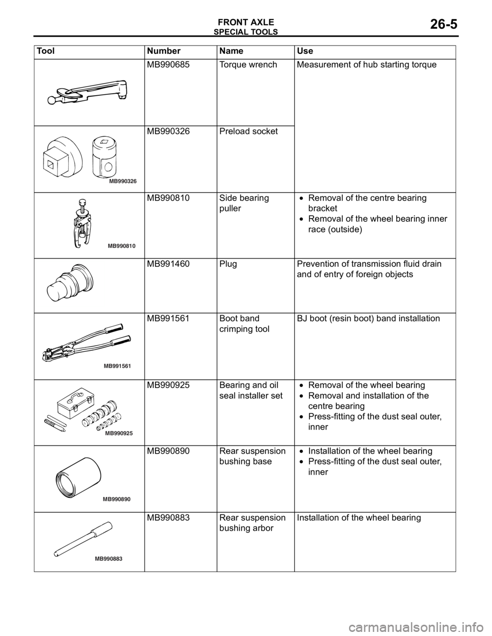
SPECIA L T OOLS
FRONT AXLE26-5
MB990685To rqu e wrenchMeas urement o f hub st arting torque
MB990326
MB990326 Prel oad socket
MB990810
MB990810Side be aring
puller•Removal of the centre b earing
bra
c ke t
•Removal of the whee l bea ring inner
r
a ce (o ut side )
MB991460PlugPreven tion of transmission fluid drain
and o
f entry of fore ign o b ject s
MB991561
MB991561Boot ban d
crimpin
g toolBJ boot (resin bo ot) ban d inst a lla tion
MB990925
MB990925Bearing and o il
seal
inst a lle r set•Removal of the whee l bea ring
•Removal and inst a lla tion o f the
centre
bearing
•Press-f i ttin g of th e dust se al ou ter ,
inner
MB990890
MB990890Rear suspension
bush
i ng b a se•In st allatio n of th e wheel bearing
•Press-f i ttin g of th e dust se al ou ter ,
inner
MB990883
MB990883Rear suspension
bush
i ng a r borInstallation of t he wheel bearing
Tool Nu mber Na me Use
Page 146 of 800
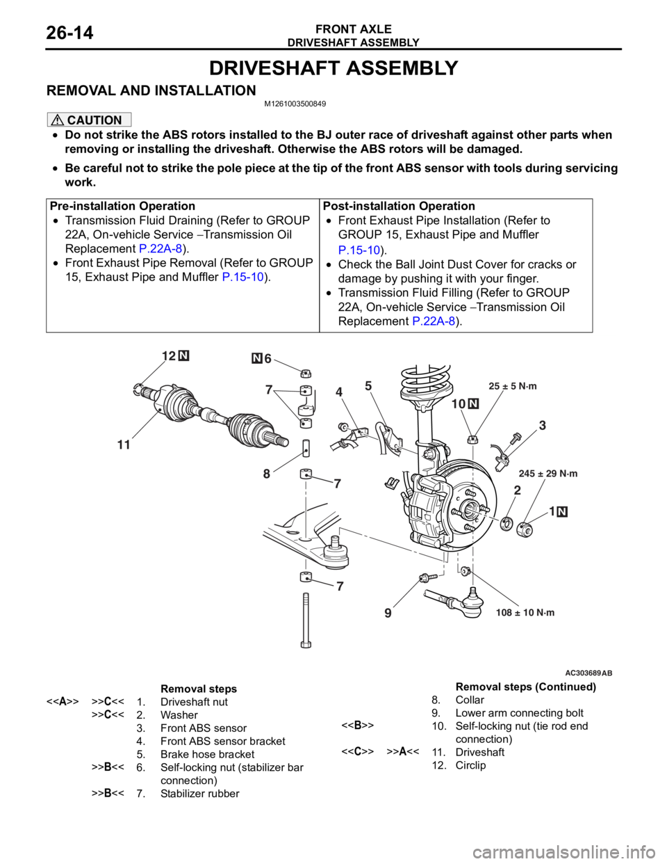
DRIVESHAFT ASSEMBLY
FRONT AXLE26-14
DRIVESHAFT ASSEMBLY
REMOVAL AND INSTALLATIONM1261003500849
CAUTION
•Do not strike the ABS rotors installed to the BJ outer race of driveshaft against other parts when
removing or installing the driveshaft. Otherwise the ABS rotors will be damaged.
•
Pre-installation Operation
•Transmission Fluid Draining (Refer to GROUP
22A, On-vehicle Service
− Transmission Oil
Replacement
P.22A-8).
•Front Exhaust Pipe Removal (Refer to GROUP
15, Exhaust Pipe and Muffler
P.15-10).
Post-installation Operation
•Front Exhaust Pipe Installation (Refer to
GROUP 15, Exhaust Pipe and Muffler
P.15-10).
•Check the Ball Joint Dust Cover for cracks or
damage by pushing it with your finger.
•Transmission Fluid Filling (Refer to GROUP
22A, On-vehicle Service
− Transmission Oil
Replacement
P.22A-8).
AC303689AB
9
N
N
NN
10
7
4
3
2 1
25 ± 5 N·m
245 ± 29 N·m
108 ± 10 N·m
8
5
6
11 12
77
Removal steps
<>>>C<<1.Driveshaft nut
>>C<<2.Washer
3.Front ABS sensor
4.Front ABS sensor bracket
5.Brake hose bracket
>>B<<6.Self-locking nut (stabilizer bar
connection)
>>B<<7.Stabilizer rubber
8.Collar
9.Lower arm connecting bolt
<>10.Self-locking nut (tie rod end
connection)
<
12.Circlip
Be careful not to strike the pole piece at the tip of the front ABS sensor with tools during servicing
work.
Removal steps (Continued)