service MITSUBISHI LANCER 2006 Workshop Manual
[x] Cancel search | Manufacturer: MITSUBISHI, Model Year: 2006, Model line: LANCER, Model: MITSUBISHI LANCER 2006Pages: 800, PDF Size: 45.03 MB
Page 7 of 800
12-1
GROUP 12
ENGINE
LUBRIC ATION
CONTENTS
GENERAL INFORMATIO N . . . . . . . .12-2
SERVICE SPECIFICATION . . . . . . . .12-2
LUBRICANT . . . . . . . . . . . . . . . . . . . .12-2
SEALANT . . . . . . . . . . . . . . . . . . . . . .12-3
SPECIAL TOOLS . . . . . . . . . . . . . . . .12-3
ON-VEHICLE SERVICE . . . . . . . . . . .12-4
ENGINE OIL CHECK . . . . . . . . . . . . . . . . . 12-4
ENGINE OIL REPLACEMENT . . . . . . . . . . 12-4
ENGINE OIL FILTER REPLACEMENT . . . . 12-4
OIL PRESSURE CHECK . . . . . . . . . . . . . . 12-5
Page 8 of 800

GENERAL INFORMATION
ENGINE LUBRICATION12-2
GENERAL INFORMATION
M1121000100357
The lubrication method is a fully force-fed, full-flow fil-
tration type. The engine oil pump is a trochoid type
which is driven by the crankshaft <4G1>.The engine
oil pump is a gear type which is driven by the crank
-
shaft via the balancer timing belt <4G6>.
ENGINE OILS
Health Warning
Prolonged and repeated contact with mineral oil will
result in the removal of natural fats from the skin,
leading to dryness, irritation and dermatitis. In addi
-
tion, used engine oil contains potentially harmful con-
taminants which may cause skin cancer. Adequate
means of skin protection and washing facilities must
be provided.
Recommended Precautions
The most effective precaution is to adapt working
practices which prevent, as far as practicable, the
risk of skin contact with mineral oils, for example by
using enclosed systems for handling used engine oil
and by degreasing components, where practicable,
before handling them. Other precautions:
•Avoid prolonged and repeated contact with oils,
particularly used engine oils.
•Wear protective clothing, including impervious
gloves where practicable.
•Avoid contaminating clothes, particularly under-
pants, with oil.
•Do not put oily rags in pockets, the use of overalls
without pockets will avoid this.
•Do not wear heavily soiled clothing and
oil-impregnated foot-wear. Overalls must be
cleaned regularly and kept separate from per
-
sonal clothing.
•Where there is a risk of eye contact, eye protec-
tion should be worn, for example, chemical gog-
gles or face shields; in addition an eye wash
facility should be provided.
•Obtain first aid treatment immediately for open
cuts and wounds.
•Wash regularly with soap and water to ensure all
oil is removed, especially before meals (skin
cleansers and nail brushes will help). After clean
-
ing, the application of preparations containing
lanolin to replace the natur al skin oils is advised.
•Do not use petrol, kerosine, diesel fuel, gas oil,
thinners or solvents for cleaning skin.
•Use barrier creams, applying them before each
work period, to help the removal of oil from the
skin after work.
•If skin disorders develop, obtain medical advice
without delay.
SERVICE SPECIFICATION
M1121000300232
ItemStandard value
Oil pressure kPaat idle29 or more
at 3,500 r/min294 − 686
LUBRICANT
M1121000400433
ItemSpecification
Engine oil ACEA classificationA1, A2 or A3
Engine oil API classificationSG or higher
Engine oil quantity L4G1Oil filter0.3
To t a l3.3
4G6Oil filter0.3
To t a l4.3
Page 10 of 800
ON-VEHICLE SERVICE
ENGINE LUBRICATION12-4
ON-VEHICLE SERVICE
ENGINE OIL CHECKM1121000900342
ACX00892 AC
Good
Maximum Minimum
<4G1>
AC205268
Maximum MinimumGood
AC
<4G6>
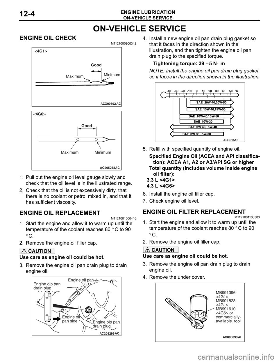
1.
Pull ou t the en gine oil level ga uge slowly and
check tha t the o il level is in t he illustrated range.
2.Check t hat the oil is not excessively dirty , that
th ere is no coolant or p e trol mixed in, and that it
ha s s u f f i c ie nt vi sc osi t y .
ENGINE OIL REPLACEMENT
M1121 0010 0041 6
1.S t art the engin e and allow it to war m up until the
te mpera t ure of the coola n t reaches 80
°C to 90
°C.
2.Remove the en gine oil filler ca p.
CAUTION
Use care as engine oil could be hot.
3. Remove the engine oil pan drain plug to drain
engine oil.
AC208299
Engine oil pan
AC
Engine oip pan
drain plug
Engine oip pan
drain plug
Engine oil
pan side
4. Install a new engine oil pan drain plug gasket so
that it faces in the direction shown in the
illustration, and then tighten the engine oil pan
drain plug to the specified torque.
Tightening torque: 39 ± 5 N⋅m
NOTE: Install the engine oil pan drain plug gasket
so it faces in the direction shown in the illustration.
AC301513
5. Refill with specifi ed quantity of engine oil.
Specified Engine Oil (ACEA and API classifica-
tion): ACEA A1, A2 or A3/API SG or higher
Total quantity (Includes volume inside engine
oil filter):
3.3 L <4G1>
4.3 L <4G6>
6. Install the engine oil filler cap.
7. Check engine oil level.
ENGINE OIL FILTER REPLACEMENTM1121001100383
1. Start the engine and allow it to warm up until the temperature of the coolant reaches 80
°C to 90
°C.
2. Remove the engine oil filler cap.
CAUTION
Use care as engine oil could be hot.
3. Remove the engine oil pan drain plug to drain engine oil.
4. Remove the under cover.
AC000093
MB991396
<4G1>,
MB991828
<4G1>,
MB991610
<4G6> or
commercially-
available tool
AI
Page 11 of 800
ON-VEHICLE SERVICE
ENGINE LUBRICATION12-5
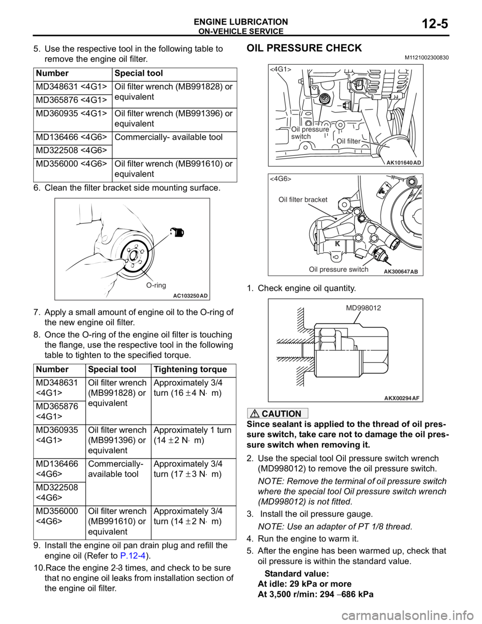
5. Use the respective tool in the following table to remove the engine oil filter.
NumberSpecial tool
MD348631 <4G1>Oil filter wrench (MB991828) or
equivalent
MD365876 <4G1>
MD360935 <4G1>Oil filter wrench (MB991396) or
equivalent
MD136466 <4G6>Commercially- available tool
MD322508 <4G6>
MD356000 <4G6>Oil filter wrench (MB991610) or
equivalent
6. Cle an the filt er bracket side mou n ting surfa c e.
AC103250AD
O-ring
7.Ap ply a small a m ou nt o f en gine o i l to th e O-rin g of
th e new eng ine oil f ilte r .
8.Once the O-ring of the engine oil filter is tou c hing
th e flange, use the resp ective tool in the following
t able to tighten to the specified tor que.
NumberSpecial toolTightening torque
MD348631
<4G1>Oil filter wrench
(MB991828) or
equivalentApproximately 3/4
turn (16
± 4 N⋅m)
MD365876
<4G1>
MD360935
<4G1>Oil filter wrench
(MB991396) or
equivalentApproximately 1 turn
(14
± 2 N⋅m)
MD136466
<4G6>Commercially-
available toolApproximately 3/4
turn (17
± 3 N⋅m)
MD322508
<4G6>
MD356000
<4G6>Oil filter wrench
(MB991610) or
equivalentApproximately 3/4
turn (14
± 2 N⋅m)
9.In st all the en gine oil p a n drain plu g and refill the
en gine oil (Re f er to
P.12-4).
10.Race the en gine 2−3 times, and che ck to be sure
th
at n
o
en
gin
e
oil leaks fr om in st allation sectio n of
th
e engine oil filter
.
OIL PRESSURE CHECK
M1 121 0023 0083 0
AK101640
<4G1>
Oil pressure
switch
Oil filter
AD
AK300647
AB
<4G6>
Oil filter bracket
Oil pressure switch
1.Check e ngin e oil quan tity .
AKX00294
MD998012
AF
CAUTION
Since sealant is applied to the thread of oil pres-
sure switch, take care not to damage the oil pres-
sure switch when removing it.
2. Use the special tool Oil pressure switch wrench
(MD998012) to remove the oil pressure switch.
NOTE: Remove the terminal of oil pressure switch
where the special tool Oil pressure switch wrench
(MD998012) is not fitted.
3. Install the oil pressure gauge.
NOTE: Use an adapter of PT 1/8 thread.
4. Run the engine to warm it.
5. After the engine has been warmed up, check that oil pressure is within the standard value.
Standard value:
At idle: 29 kPa or more
At 3,500 r/min: 294 − 686 kPa
Page 12 of 800
ON-VEHICLE SERVICE
ENGINE LUBRICATION12-6
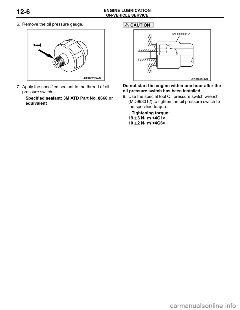
6. Remove the oil pressure gauge.
AKX00295AD
7.App l y t he sp ecified sealant to the thr ead of oil
pres sure sw itc h .
Specified sealan t: 3M A T D Part No. 8660 or
equival
ent
AKX00294
MD998012
AF
CAUTION
Do not start the engine within one hour after the
oil pressure switch has been installed.
8. Use the special tool Oil pressure switch wrench (MD998012) to tighten the oil pressure switch to
the specified torque.
Tightening torque:
19 ± 3 N⋅m <4G1>
10 ± 2 N⋅m <4G6>
Page 15 of 800
14-1
GROUP 14
ENGINE COOLING
CONTENTS
GENERAL INFORMATION . . . . . . . .14-2
SERVICE SPECIFICATIONS . . . . . . .14-2
LUBRICANT . . . . . . . . . . . . . . . . . . . .14-3
SEALANTS . . . . . . . . . . . . . . . . . . . .14-3
SPECIAL TOOLS . . . . . . . . . . . . . . . .14-3
TROUBLESHOOTING . . . . . . . . . . . .14-5
INSPECTION CHART FOR TROUBLE
SYMPTOMS . . . . . . . . . . . . . . . . . . . . . . . . 14-5
INSPECTION PROCEDURE FOR
TROUBLE SYMPTOMS . . . . . . . . . . . . . . . 14-6
ON-VEHICLE SERVICE . . . . . . . . . . .14-21
ENGINE COOLANT LEAK CHECK . . . . . . 14-21
RADIATOR CAP VALVE OPENING
PRESSURE CHECK . . . . . . . . . . . . . . . . . . 14-21
ENGINE COOLANT REPLACEMENT . . . . 14-21
CONCENTRATION MEASUREMENT . . . . 14-22
COOLING FAN MOTOR DRIVE
CONTROL UNIT CHECK . . . . . . . . . . . . . . 14-22
FAN CONTROL RELAY CONTINUITY
CHECK . . . . . . . . . . . . . . . . . . . . . . . . . . . . 14-23
COOLING FAN MOTOR CHECK . . . . . . . . 14-24
THERMOSTAT . . . . . . . . . . . . . . . . . .14-24
REMOVAL AND INSTALLATION . . . . . . . . 14-24
INSPECTION. . . . . . . . . . . . . . . . . . . . . . . . 14-26
WATER PUMP . . . . . . . . . . . . . . . . . .14-27
REMOVAL AND INSTALLATION <4G1> . . 14-27
REMOVAL AND INSTALLATION <4G6> . . 14-28
WATER HOSE AND WATER PIPE . .14-29
REMOVAL AND INSTALLATION <4G1> . . 14-29
REMOVAL AND INSTALLATION <4G6> . . 14-31
INSPECTION. . . . . . . . . . . . . . . . . . . . . . . . 14-32
RADIATOR . . . . . . . . . . . . . . . . . . . . .14-33
REMOVAL AND INSTALLATION <4G1> . . 14-33
REMOVAL AND INSTALLATION <4G6> . . 14-35
Page 16 of 800

GENERAL INFORMATION
ENGINE COOLING14-2
GENERAL INFORMATION
M1141000100371
The cooling system is designed to keep every part of
the engine at appropriate temperature in whatever
condition the engine may be operated. The cooling
method is of the water-cooled, pressure forced circu
-
lation type in which the water pump pressurizes cool-
ant and circulates it throughout the engine. If the
coolant temperature exceeds the prescribed temper
-
ature, the thermostat opens to circulate the coolant
through the radiator as well so that the heat
absorbed by the coolant may be radiated into the air.
The water pump is of the centrifugal type and is
driven by the alternator drive belt from the crank
-
shaft. The radiator is the corrugated fin, down flow
type.
ItemSpecification
RadiatorPerformance kJ/h4G13Standard vehicles137,720
Vehicles with capacity up radiator
(option)161,288
4G18Standard vehicles161,288
Vehicles with capacity up radiator
(option)181,800
4G63181,800
A/T oil coolerPerformance kJ/h5,651
SERVICE SPECIFICATIONS
M1141000300687
ItemStandard valueLimit
Fan controller VA/C OFF1 or less-
A/C ONRepeat
8.2 ± 0.7
System voltage ± 2.6
-
High-pressure valve opening pressure of radiator cap kPa93 − 123Minimum 83
Range of coolant antifreeze concentration of radiator %30 − 60-
ThermostatValve opening temperature of
thermostat
°C
4G188 ± 1.5-
4G682 ± 1.5-
Full-opening temperature of
thermostat
°C
4G1100-
4G695-
Valve lift mm8.5 or more-
Page 35 of 800
ON-VEHICLE SERVICE
ENGINE COOLING14-21
ON-VEHICLE SERVICE
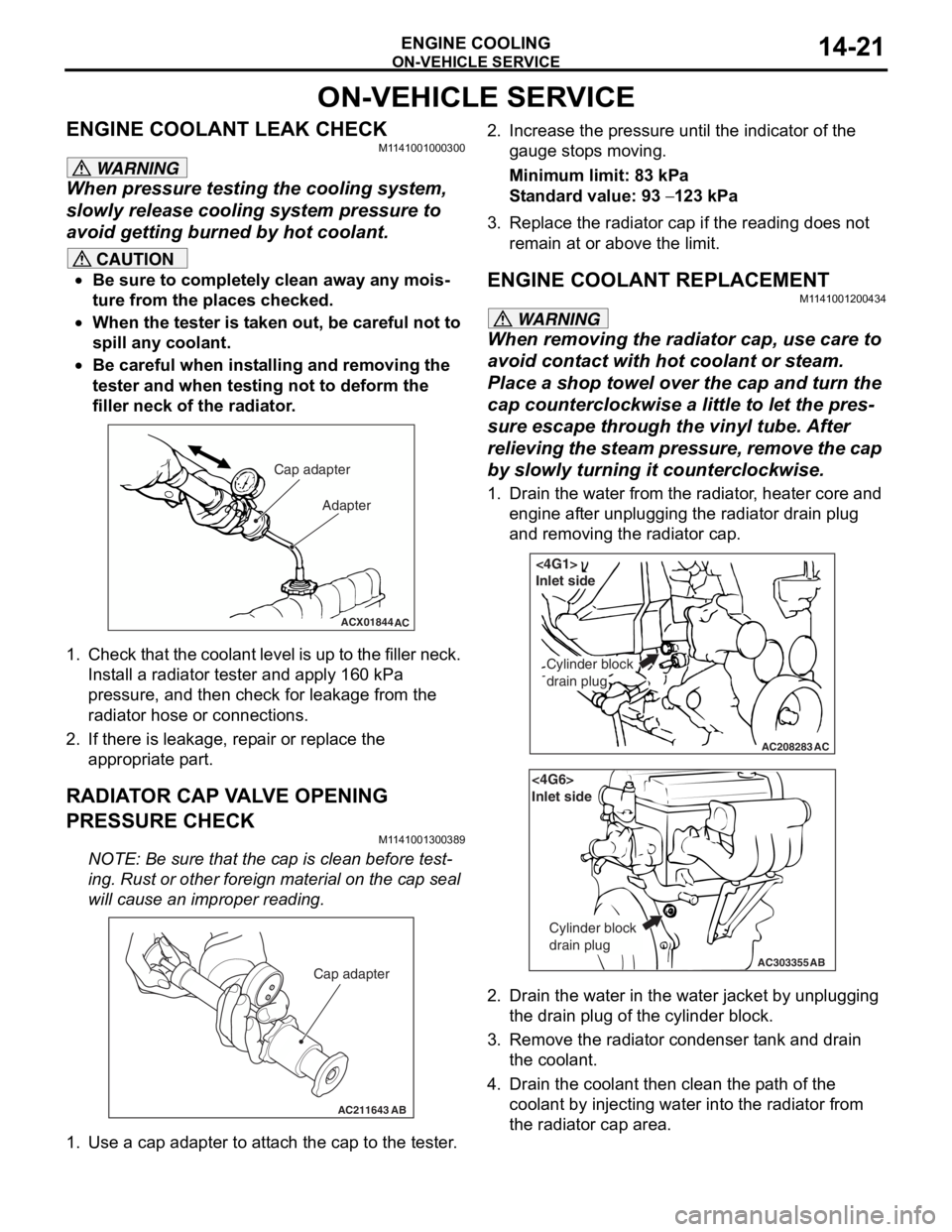
ENGINE COOLANT LEAK CHECKM1141001000300
WARNING
When pressure testing the cooling system,
slowly release cooling system pressure to
avoid getting burned by hot coolant.
CAUTION
•Be sure to completely clean away any mois-
ture from the places checked.
•When the tester is taken out, be careful not to
spill any coolant.
•
ACX01844
Cap adapter
Adapter
AC
Be careful when installing and removing the
tester and when testing not to deform the
filler neck of the radiator.
1. Check that the coolant leve l is up to the filler neck.
Install a radiator tester and apply 160 kPa
pressure, and then check for leakage from the
radiator hose or connections.
2. If there is leakage, repair or replace the
appropriate part.
RADIATOR CAP VALVE OPENING
PRESSURE CHECK
M1141001300389
NOTE: Be sure that the cap is clean before test-
ing. Rust or other foreign material on the cap seal
will cause an improper reading.
AC211643AB
Cap adapter
1. Use a cap adapter to attach the cap to the tester.
2. Increase the pressure until the indicator of the gauge stops moving.
Minimum limit: 83 kPa
Standard value: 93 − 123 kPa
3. Replace the radiator cap if the reading does not remain at or above the limit.
ENGINE COOLANT REPLACEMENT
M1141001200434
WARNING
When removing the radiator cap, use care to
avoid contact with hot coolant or steam.
Place a shop towel over the cap and turn the
cap counterclockwise a little to let the pres
-
sure escape through the vinyl tube. After
relieving the steam pres sure, remove the cap
by slowly turning it counterclockwise.
1. Drain the water from the radiator, heater core and
engine after unplugging the radiator drain plug
and removing the radiator cap.
AC208283AC
Cylinder block
drain plug
<4G1>
Inlet side
AC303355
<4G6>
Inlet side
Cylinder block
drain plug
AB
2. Drain the water in the water jacket by unplugging the drain plug of the cylinder block.
3. Remove the radiator condenser tank and drain
the coolant.
4. Drain the coolant then clean the path of the coolant by injecting water into the radiator from
the radiator cap area.
Page 37 of 800
ON-VEHICLE SERVICE
ENGINE COOLING14-23
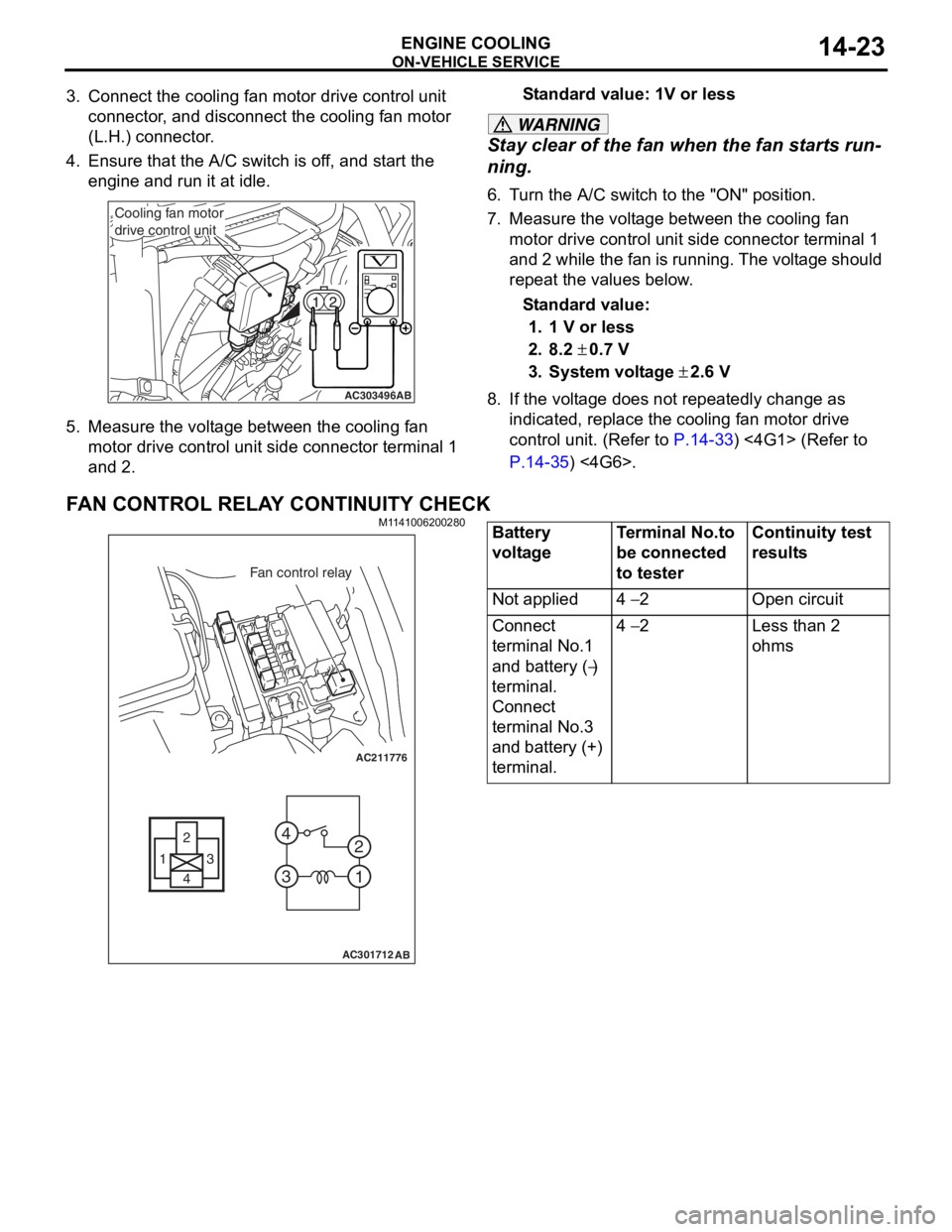
3. Connect the cooling fan motor drive control unit connector, and disconnect the cooling fan motor
(L.H.) connector.
4. Ensure that the A/C switch is off, and start the engine and run it at idle.
AC303496AB
Cooling fan motor
drive control unit
5.Measure the volt ag e betwee n the cooling f an
motor d r ive cont rol un it side conne ctor t e rminal 1
an d 2.
St andard va lue: 1V or le ss
WARNING
Stay clear of the fan when the fan starts run-
ning.
6. Turn the A/C switch to the "ON" position.
7. Measure the voltage between the cooling fan
motor drive control unit side connector terminal 1
and 2 while the fan is running. The voltage should
repeat the values below.
Standard value:
1. 1 V or less
2. 8.2 ± 0.7 V
3. System voltage ± 2.6 V
8. If the voltage does not repeatedly change as indicated, replace the cooling fan motor drive
control unit. (Refer to
P.14-33) <4G1> (Refer to
P.14-35) <4G6>.
FAN CONTROL RELAY CONTINUITY CHECK
M1141006200280
AC211776
13
4 2
3 4
1
2
AC301712
Fan control relay
AB
Battery
voltageTerminal No.to
be connected
to testerContinuity test
results
Not applied4 − 2Open circuit
Connect
terminal No.1
and battery (
−)
terminal.
Connect
terminal No.3
and battery (+)
terminal.
4 − 2Less than 2
ohms
Page 44 of 800
WATER HOSE AND WATER PIPE
ENGINE COOLING14-30
INSTALLATION SERVICE POINTS
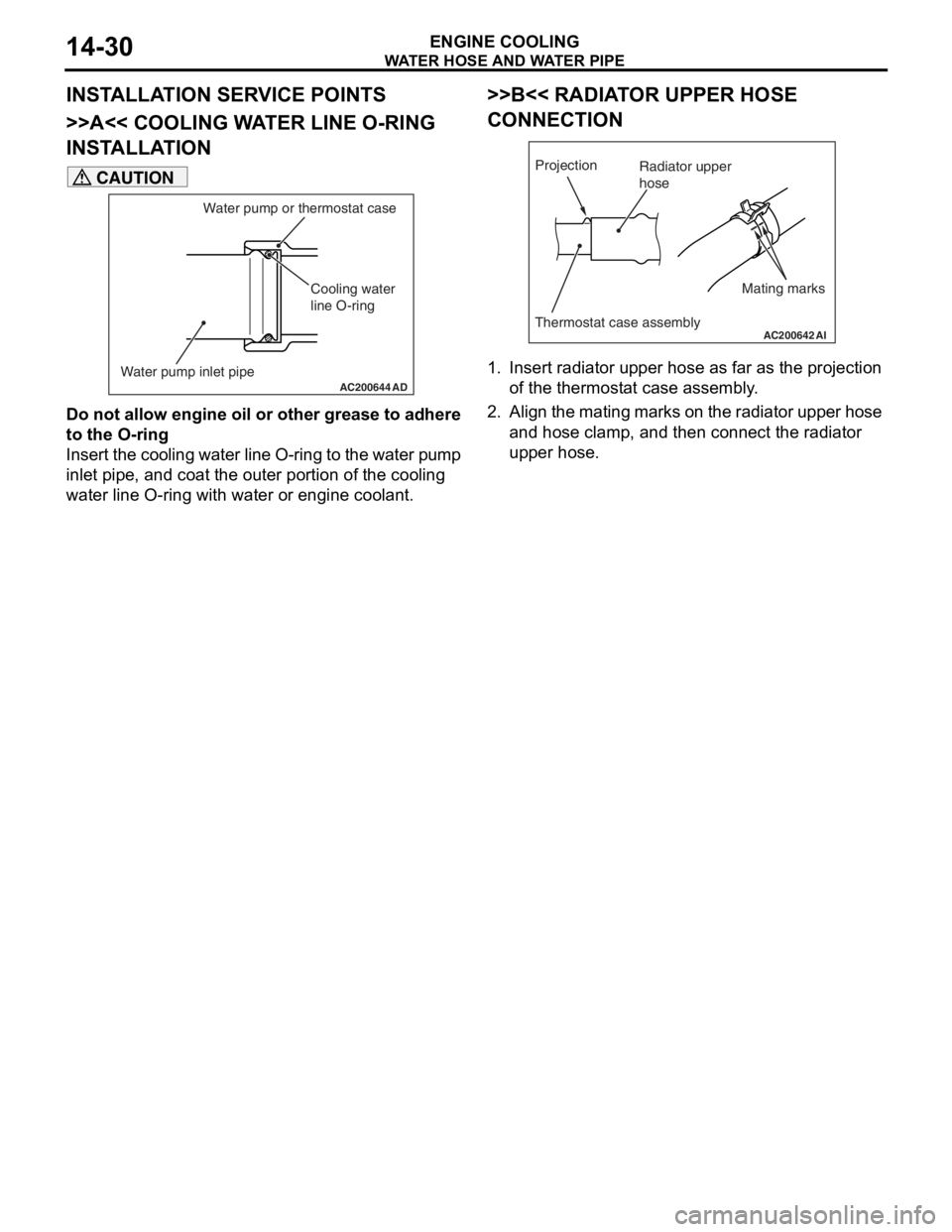
>>A<< COOLING WATER LINE O-RING
INSTALLATION
AC200644 AD
Cooling water
line O-ring
Water pump inlet pipe Water pump or thermostat case
CAUTION
Do not allow engine oil or other grease to adhere
to the O-ring
Insert the cooling water line O-ring to the water pump
inlet pipe, and coat the outer portion of the cooling
water line O-ring with water or engine coolant.
>>B<< RADIATOR UPPER HOSE
CONNECTION
AC200642
Mating marks
Projection
Thermostat case assemblyAI
Radiator upper
hose
1. Insert radiator upper hose as far as the projection
of the thermostat case assembly.
2. Align the mating marks on the radiator upper hose and hose clamp, and then connect the radiator
upper hose.