Trunk MITSUBISHI LANCER 2006 Workshop Manual
[x] Cancel search | Manufacturer: MITSUBISHI, Model Year: 2006, Model line: LANCER, Model: MITSUBISHI LANCER 2006Pages: 800, PDF Size: 45.03 MB
Page 274 of 800
42-2
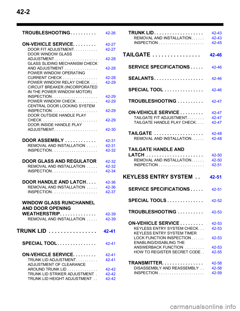
TROUBLESHOOTING . . . . . . . . . .42-26
ON-VEHICLE SERVICE. . . . . . . . .42-27
DOOR FIT ADJUSTMENT. . . . . . . . . . . 42-27
DOOR WINDOW GLASS
ADJUSTMENT . . . . . . . . . . . . . . . . . . . . 42-28
GLASS SLIDING MECHANISM CHECK
AND ADJUSTMENT . . . . . . . . . . . . . . . 42-28
POWER WINDOW OPERATING
CURRENT CHECK . . . . . . . . . . . . . . . . 42-28
POWER WINDOW RELAY CHECK . . . 42-29
CIRCUIT BREAKER (INCORPORATED
IN THE POWER WINDOW MOTOR)
INSPECTION . . . . . . . . . . . . . . . . . . . . . 42-29
POWER WINDOW CHECK . . . . . . . . . . 42-29
CENTRAL DOOR LOCKING SYSTEM
INSPECTION . . . . . . . . . . . . . . . . . . . . . 42-29
DOOR OUTSIDE HANDLE PLAY
CHECK . . . . . . . . . . . . . . . . . . . . . . . . . 42-29
DOOR INSIDE HANDLE PLAY
ADJUSTMENT . . . . . . . . . . . . . . . . . . . . 42-30
DOOR ASSEMBLY . . . . . . . . . . . .42-31
REMOVAL AND INSTALLATION . . . . . 42-31
INSPECTION . . . . . . . . . . . . . . . . . . . . . 42-32
DOOR GLASS AND REGULATOR42-32
REMOVAL AND INSTALLATION . . . . . 42-32
INSPECTION . . . . . . . . . . . . . . . . . . . . . 42-34
DOOR HANDLE AND LATCH . . . .42-36
REMOVAL AND INSTALLATION . . . . . 42-36
INSPECTION . . . . . . . . . . . . . . . . . . . . . 42-37
WINDOW GLASS RUNCHANNEL
AND DOOR OPENING
WEATHERSTRIP . . . . . . . . . . . . . .42-39
REMOVAL AND INSTALLATION . . . . . 42-39
TRUNK LID . . . . . . . . . . . . . . . .42-41
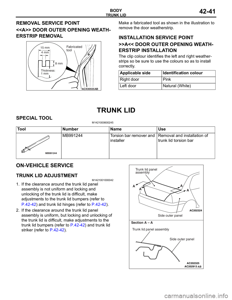
SPECIAL TOOL . . . . . . . . . . . . . . .42-41
ON-VEHICLE SERVICE. . . . . . . . .42-41
TRUNK LID ADJUSTMENT . . . . . . . . . . 42-41
ADJUSTMENT OF CLEARANCE
AROUND TRUNK LID . . . . . . . . . . . . . . 42-42
TRUNK LID STRIKER ADJUSTMENT . 42-42
TRUNK LID HEIGHT ADJUSTMENT . . 42-42
TRUNK LID . . . . . . . . . . . . . . . . . . .42-43
REMOVAL AND INSTALLATION . . . . . . 42-43
INSPECTION . . . . . . . . . . . . . . . . . . . . . 42-45
TAILGATE . . . . . . . . . . . . . . . . 42-46
SERVICE SPECIFICATIONS . . . . .42-46
SEALANTS . . . . . . . . . . . . . . . . . . .42-46
SPECIAL TOOL . . . . . . . . . . . . . . .42-46
TROUBLESHOOTING . . . . . . . . . .42-47
ON-VEHICLE SERVICE . . . . . . . . .42-47
TAILGATE FIT ADJUSTMENT. . . . . . . . 42-47
TAILGATE HANDLE PLAY CHECK . . . . 42-47
TAILGATE . . . . . . . . . . . . . . . . . . .42-48
REMOVAL AND INSTALLATION . . . . . . 42-48
TAILGATE HANDLE AND
LATCH . . . . . . . . . . . . . . . . . . . . . .42-50
REMOVAL AND INSTALLATION . . . . . . 42-50
INSPECTION . . . . . . . . . . . . . . . . . . . . . 42-51
KEYLESS ENTRY SYSTEM . . 42-51
SERVICE SPECIFICATIONS . . . . .42-51
SPECIAL TOOLS . . . . . . . . . . . . . .42-52
TROUBLESHOOTING . . . . . . . . . .42-53
ON-VEHICLE SERVICE . . . . . . . . .42-53
KEYLESS ENTRY SYSTEM CHECK. . . 42-53
KEYLESS ENTRY SYSTEM TIMER
LOCK FUNCTION INSPECTION . . . . . . 42-53
ENABLING/DISABLING THE
ANSWERBACK FUNCTION . . . . . . . . . 42-53
HOW TO REGISTER SECRET CODE . 42-55
TRANSMITTER. . . . . . . . . . . . . . . .42-58
DISASSEMBLY AND REASSEMBLY . . 42-58
INSPECTION . . . . . . . . . . . . . . . . . . . . . 42-59
Page 313 of 800
Page 314 of 800
TRUNK LID
BODY42-42
3. If there is a difference in height between the side outer panels and the side edges of the trunk lid
panel assembly, check the trunk lid hinges and, if
necessary, replace them
4. If the clearance around the trunk lid panel assembly is not uniform, and the trunk lid can be
locked and unlocked smoothly, make adjustments
to the trunk lid bumpers (refer to
P.42-42) and
trunk lid hinges (Refer to P.42-42).
5. If the locking and unlocking of the trunk lid still is difficult after making the above adjustments,
adjust the trunk lid striker (Refer to
P.42-42).
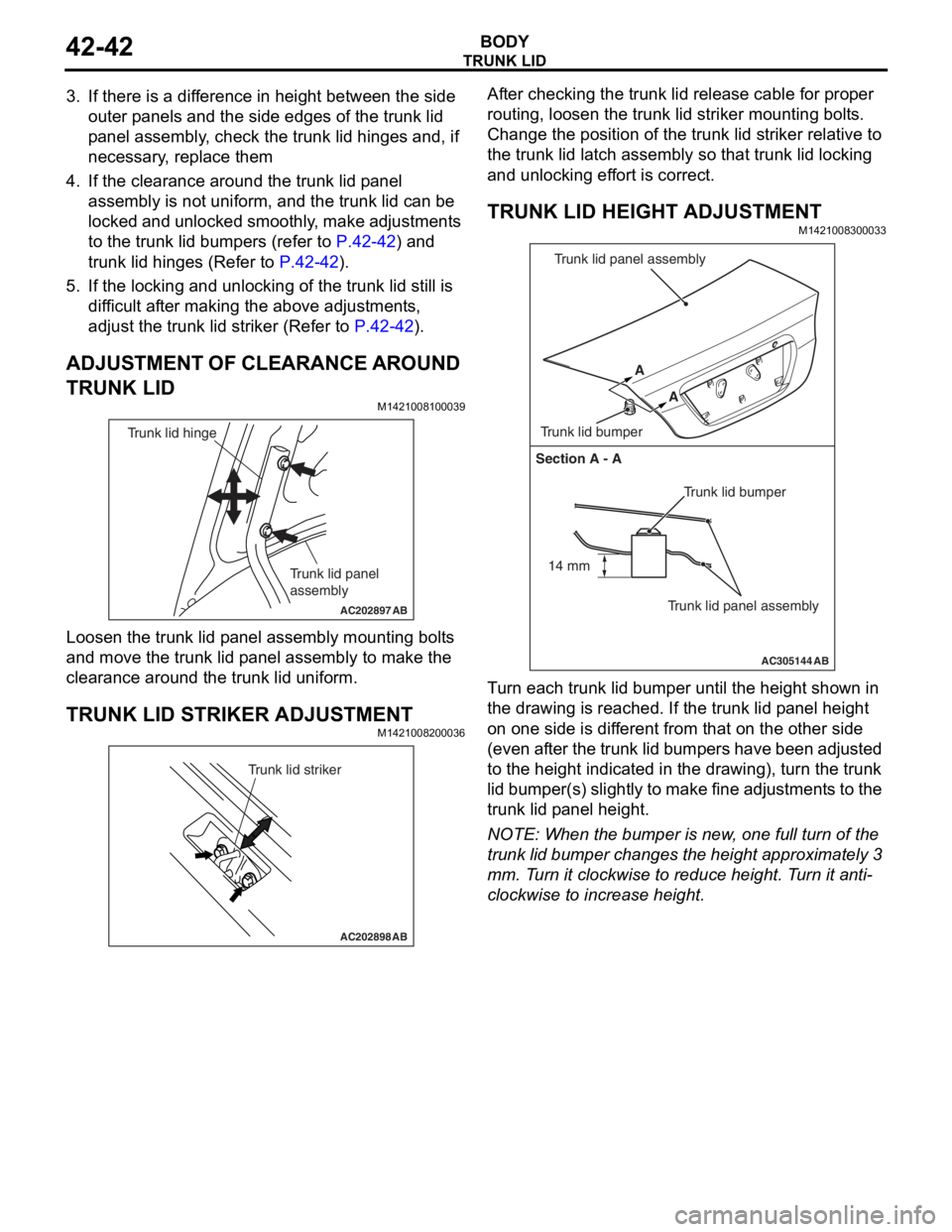
ADJUSTMENT OF CLEARANCE AROUND
TRUNK LID
M1421008100039
AC202897
Trunk lid panel
assembly
Trunk lid hinge
AB
Loosen the trunk lid p a nel a sse mbly mounting bolt s
and move
the trun k lid p anel assembly to make t he
clea
rance aroun d the t r unk lid u n iform.
TRUNK LID STRIKER ADJUSTMENT
M14210082 0003 6
AC202898
Trunk lid striker
AB
After checking the trunk lid relea s e cable for pro per
routin
g, lo osen the trun k lid striker mo untin g bolt s .
Ch
ange th e position of t he trunk lid st rike r relat i ve to
the trun
k lid la tch a s sembly so tha t trunk lid lockin g
and un
lockin g ef f o rt is corre ct.
TRUNK LID HEIGHT ADJUSTMENT
M14210083 0003 3
AC305144
Section A - A
Trunk lid bumper
Trunk lid panel assembly
A
A
Trunk lid bumper Trunk lid panel assembly
AB
14 mm
T
u rn each trun k lid bumper u n til the he ight shown in
the dra
w ing is reached. If the t r unk lid p a n e l he ight
on one
sid e is dif f erent from that on the oth e r side
(even
a f t e r th e t r un k lid bu mp ers have be en ad ju st ed
to the h
e igh t ind i ca ted in the dra w ing), tu rn the trunk
lid bumper(s)
slight ly to make fine adjustment s to the
trunk lid p
a nel h e ight .
NOTE: Whe n the b u mpe r is new , one full turn o f the
trunk lid bumper ch anges t he height appro x imately 3
mm.
T
u
rn it clockwise to r educe height. T u rn it anti
-
clockwise to increase height.
Page 315 of 800
TRUNK LID
BODY42-43
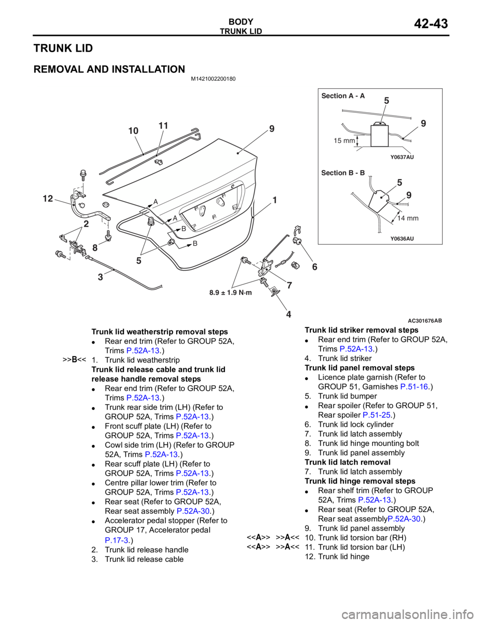
TRUNK LID
REMOVAL AND INSTALLATION
M1421002200180
AC301676
Y0636AU
Y0637AU
AB
8.9 ± 1.9 N·m
A
AB
B 15 mm
14 mm
Section A - A
Section B - B
9
5
6
4
12
9
59
7
11
10
8 3 5 1
2
Trunk lid weatherstrip removal steps
•Rear end trim (Refer to GROUP 52A,
Trims
P.52A-13.)
>>B<<1.Trunk lid weatherstrip
Trunk lid release cable and trunk lid
release handle removal steps
•Rear end trim (Refer to GROUP 52A,
Trims
P.52A-13.)
•Trunk rear side trim (LH) (Refer to
GROUP 52A, Trims
P.52A-13.)
•Front scuff plate (LH) (Refer to
GROUP 52A, Trims
P.52A-13.)
•Cowl side trim (LH) (Refer to GROUP
52A, Trims
P.52A-13.)
•Rear scuff plate (LH) (Refer to
GROUP 52A, Trims
P.52A-13.)
•Centre pillar lower trim (Refer to
GROUP 52A, Trims
P.52A-13.)
•Rear seat (Refer to GROUP 52A,
Rear seat assembly
P.52A-30.)
•Accelerator pedal stopper (Refer to
GROUP 17, Accelerator pedal
P.17-3.)
2.Trunk lid release handle
3.Trunk lid release cable
Trunk lid striker removal steps
•Rear end trim (Refer to GROUP 52A,
Trims
P.52A-13.)
4.Trunk lid striker
Trunk lid panel removal steps
•Licence plate garnish (Refer to
GROUP 51, Garnishes
P.51-16.)
5.Trunk lid bumper
•Rear spoiler (Refer to GROUP 51,
Rear spoiler
P.51-25.)
6.Trunk lid lock cylinder
7.Trunk lid latch assembly
8.Trunk lid hinge mounting bolt
9.Trunk lid panel assembly
Trunk lid latch removal
7.Trunk lid latch assembly
Trunk lid hinge removal steps
•Rear shelf trim (Refer to GROUP
52A, Trims
P.52A-13.)
•Rear seat (Refer to GROUP 52A,
Rear seat assembly
P.52A-30.)
9.Trunk lid panel assembly
<>>>A<<10.Trunk lid torsion bar (RH)
<>>>A<<11 .Trunk lid torsion bar (LH)
12.Trunk lid hinge
Page 316 of 800
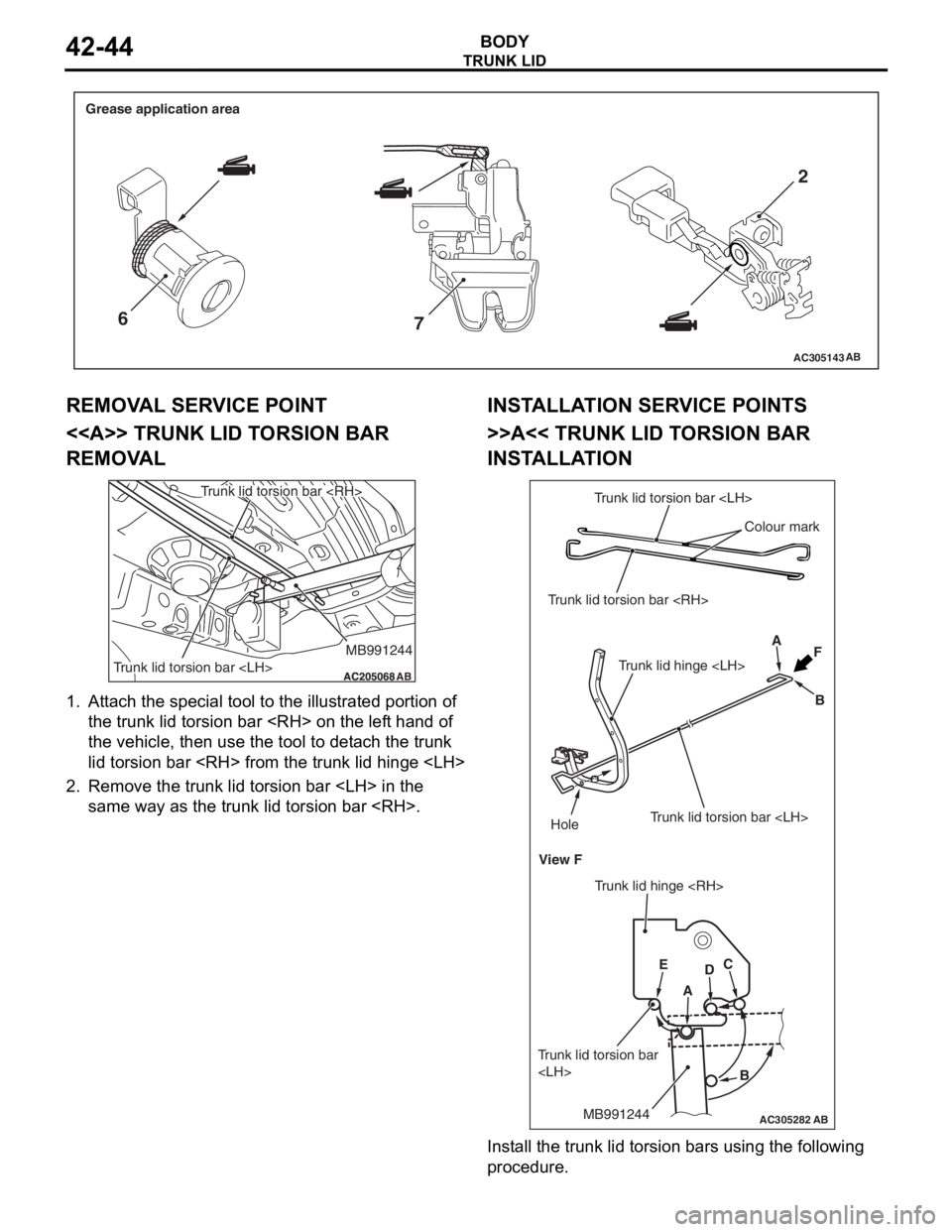
AC305143AB
Grease application area
62
7
TRUNK LID
BODY42-44
REMOV A L SER V ICE POINT
<> TRUNK LID T O RSION BAR
REMOV
A L
AC205068AC205068
MB991244
Trunk lid torsion bar
Trunk lid torsion bar
AB
1. Att a ch the special tool to the illustrat ed port i on o f
th e trunk lid torsion b a r
th e veh i cle, the n use the t ool to det ach the tru n k
lid to rsio n bar
2.Remove the tru n k lid to rsio n bar
same wa y as the t r unk lid t o rsion bar
INSTALLA T ION SER VICE POINTS
>>A<< TRUNK LID T O RSION BAR
INST
ALLA TION
AC305282
Trunk lid torsion bar
Trunk lid torsion bar
Colour mark
A
B
Trunk lid hinge
Trunk lid torsion bar
View F
Trunk lid hinge
Hole
F
E
A
DC
B
MB991244
Trunk lid torsion bar
AB
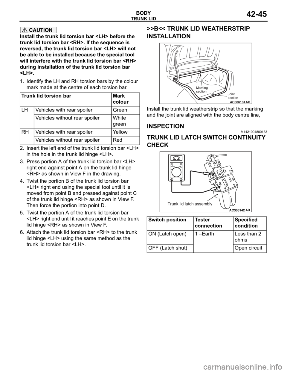
Inst all the t r unk lid torsion bars using t he followin g
proce
dure.
Page 317 of 800
TRUNK LID
BODY42-45
CAUTION
Install the trunk lid torsion bar
trunk lid torsion bar
reversed, the trunk lid torsion bar
be able to be installed because the special tool
will interfere with the trunk lid torsion bar
during installation of the trunk lid torsion bar
1. Identify the LH and RH torsion bars by the colour mark made at the centre of each torsion bar.
Trunk lid torsion barMark
colour
LHVehicles with rear spoilerGreen
Vehicles without rear spoilerWhite
green
RHVehicles with rear spoilerYe l l o w
Vehicles without rear spoilerRed
2. Insert the left end of the trunk lid torsion bar
3. Press portion A of the trunk lid torsion bar
right end against point A on the trunk lid hinge
4. Twist the portion B of the trunk lid torsion bar
moved from point B and pressed against point C
of the trunk lid hinge
Then force the portion into point D.
5. Twist the portion A of the trunk lid torsion bar
lid hinge
6. Attach the trunk lid torsion bar
trunk lid torsion bar
>>B<< TRUNK LID WEATHERSTRIP
INSTALLATION
AC006104AB
Joint
section
Marking
section
Install the trunk lid weatherstrip so that the marking
and the joint are aligned with the body centre line,
INSPECTION
M1421004800133
TRUNK LID LATCH SWITCH CONTINUITY
CHECK
AC305142AB
Trunk lid latch assembly
Switch positionTester
connectionSpecified
condition
ON (Latch open)1 − Earth Less than 2
ohms
OFF (Latch shut)Open circuit
Page 348 of 800
GARNISHES
EXTERIOR51-16
GARNISHES
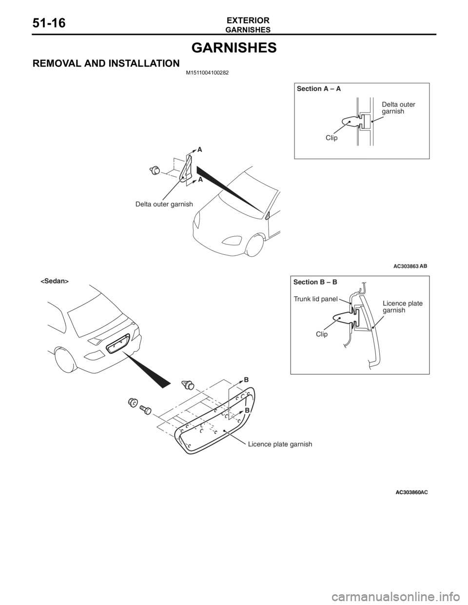
REMOVAL AND INSTALLATIONM1511004100282
AC303863
Clip
Delta outer garnish Section A – A
AB
Delta outer
garnish
A
A
AC303860
B
Clip
Trunk lid panel
Licence plate
garnish
Section B – B
AC
Licence plate garnish
B
Page 357 of 800
REAR SPOILER
EXTERIOR51-25
REAR SPOILER
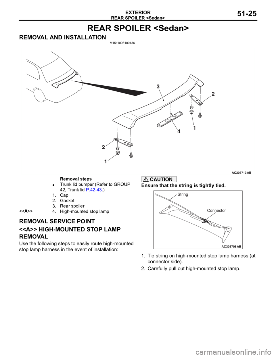
REMOVAL AND INSTALLATIONM1511006100136
AC303713
2
3
4
2 1
AB
1
Removal steps
•Trunk lid bumper (Refer to GROUP
42, Trunk lid
P.42-43.)
1.Cap
2.Gasket
3.Rear spoiler
<>4.High-mounted stop lamp
REMOV A L SER V ICE POINT
< > HIGH-MOUNTED ST OP LAMP
REMOV
A L
Use the following step s to ea sily ro ute high-mounted
stop
lamp harne ss in the eve n t of inst allation:
CAUTION
Ensure that the string is tightly tied.
AC303708
Connector
String
AB
1. Tie string on high-mounted stop lamp harness (at
connector side).
2. Carefully pull out high-mounted stop lamp.
Page 374 of 800
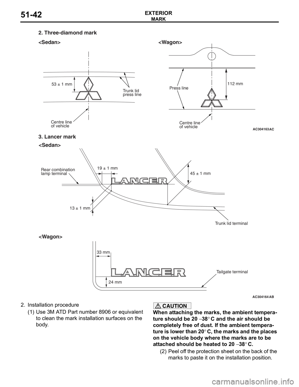
AC304163
2. Three-diamond mark
Centre line
of vehicleCentre line
of vehicle
Trunk lid
press linePress line
112 mm
53 ± 1 mm
AC
AC304164
3. Lancer mark
Rear combination
lamp terminal
Trunk lid terminalTailgate terminal
33 mm 24 mm 45 ± 1 mm
13 ± 1 mm 19 ± 1 mm
AB
MARK
EXTERIOR51-42
2.
In st allation procedure
(1)U se 3 M A T D Pa rt number 890 6 or eq uivalen t
to clean the mark inst allation surface s on the
body .
CAUTION
When attaching the marks, the ambient tempera-
ture should be 20 − 38°C and the air should be
completely free of dust. If the ambient tempera
-
ture is lower than 20°C, the marks and the places
on the vehicle body where the marks are to be
attached should be heated to 20
− 38°C.
(2) Peel off the protection sheet on the back of the marks to paste it on the installation position.
Page 411 of 800
80-1
GROUP 80
CONFIGURATION
DIAGRAMS
CONTENTS
OVERALL CONFIGURATION DIAGRAM
OVERALL WIRING DIAGRAM
OVERALL WIRING DIAGRAM
OVERALL WIRING DIAGRAM
OVERALL WIRING DIAGRAM
ENGINE COMPARTMENT
ENGINE COMPARTMENT
ENGINE COMPARTMENT
ENGINE AND TRANSMISSION
ENGINE AND TRANSMISSION
<4G1-MPI (LHD)> . . . . . . . . . . . . . . . . . . . . 80-10
ENGINE AND TRANSMISSION
<4G1-MPI (RHD)> . . . . . . . . . . . . . . . . . . . 80-14
ENGINE AND TRANSMISSION
<4G6-MPI (LHD)> . . . . . . . . . . . . . . . . . . . . 80-18
ENGINE AND TRANSMISSION
<4G6-MPI (RHD)> . . . . . . . . . . . . . . . . . . . 80-22
DASH PANEL
DASH PANEL
DASH PANEL
FLOOR AND ROOF
FLOOR AND ROOF
FLOOR AND ROOF
FLOOR AND ROOF
FLOOR AND ROOF
DOOR
DOOR
DOOR
TRUNK (LUGGAGE COMPARTMENT)
TRUNK (LUGGAGE COMPARTMENT)
TRUNK (LUGGAGE COMPARTMENT)
TAILGATE
TAILGATE
TAILGATE