rear view mirror MITSUBISHI LANCER 2006 Workshop Manual
[x] Cancel search | Manufacturer: MITSUBISHI, Model Year: 2006, Model line: LANCER, Model: MITSUBISHI LANCER 2006Pages: 800, PDF Size: 45.03 MB
Page 284 of 800

WINDOW GLASS
BODY42-12
WINDSHIELD
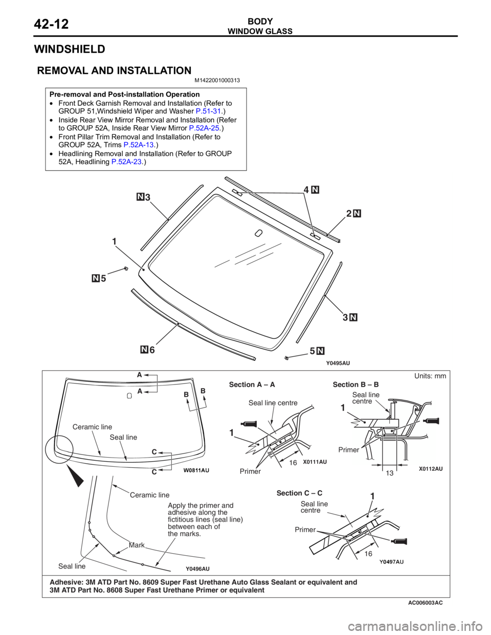
REMOVAL AND INSTALLATION
M1422001000313
Pre-removal and Post-installation Operation
•Front Deck Garnish Removal and Installation (Refer to
GROUP 51,Windshield Wiper and Washer P.51-31.)
•Inside Rear View Mirror Removal and Installation (Refer
to GROUP 52A, Inside Rear View Mirror P.52A-25.)
•Front Pillar Trim Removal and Installation (Refer to
GROUP 52A, Trims P.52A-13.)
•Headlining Removal and Installation (Refer to GROUP
52A, Headlining P.52A-23.)
AC006003
X0111AUX0112AU
Y0496AU
12
3
4
6 1
1
3
N
N
N
N
N
AC
Y0495AU
A
A BB
C C
Ceramic line
Seal line
Seal line
Ceramic line
MarkMark
Apply the primer and
adhesive along the
fictitious lines (seal line)
between each of
the marks.
Seal line centre
Primer
Section A – A Section B – B
Section C – C
Seal line
centre
Primer
5N
5N
Units: mm
Adhesive: 3M ATD Part No. 8609 Super Fast Urethane Auto Glass Sealant or equivalent and
3M ATD Part No. 8608 Super Fast Urethane Primer or equivalent
16 16
1
Seal line
centre
Primer
13
Page 377 of 800

DOOR MIRROR
EXTERIOR51-45
STEP 2. Connector check: C-212 junction block
connector
AC304913
21716151718
201912345
623 222425282627981011141213
Connector: C-212
Harness side
AB
Junction block (Front view)
Q: Is t h e che c k r esu lt n o rmal?
YES : Intermittent malfun ctio n (Refer to GROUP
00
− Ho w to Cope wit h Intermitte nt
Ma
lfunction
P.00-5).
NO : Repa ir th e defective connector .
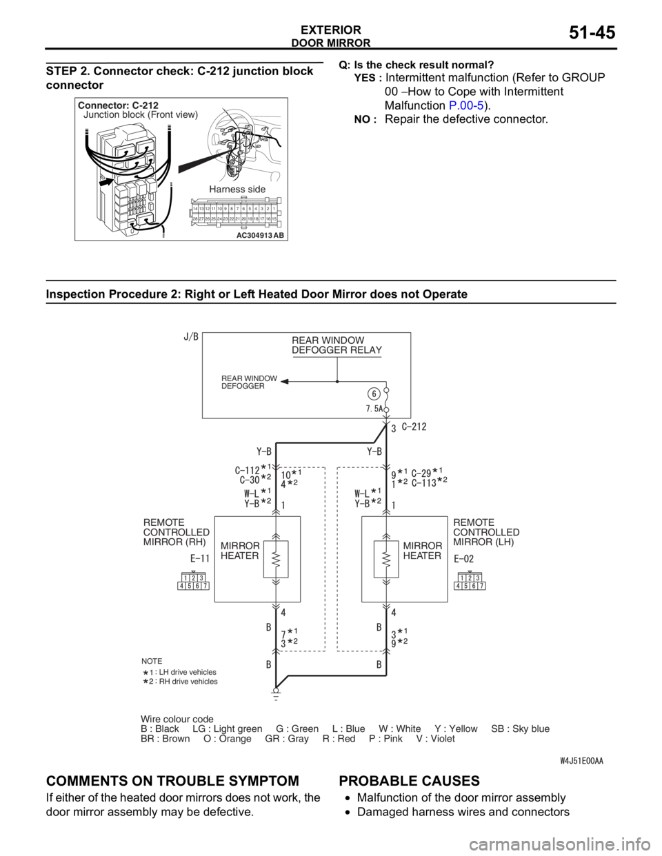
Inspection Procedure 2 : Ri ght or Lef t Hea t ed Door Mirror does not Operate
Wire colour code
B : Black LG : Light green G : Green L : Blue W : White \
Y : Yellow SB : Sky blue
BR : Brown O : Orange GR : Gray R : Red P : Pink V :\
Violet REAR WINDOW
DEFOGGER RELAY
REAR WINDOW
DEFOGGER
REMOTE
CONTROLLED
MIRROR (LH)
REMOTE
CONTROLLED
MIRROR (RH)
MIRROR
HEATER MIRROR
HEATER
NOTELH drive vehicles
RH drive vehicles
COMM
ENT S ON TROUBL E SYMPT O M
If eit her of t he hea ted d oor mirrors does n o t work, the
door mirror a
sse mbly may b e defe c tive.
PROBABLE CAUSES
•Malfunctio n of th e door mirro r assemb ly
•Damaged ha rness wires and con necto rs
Page 379 of 800

DOOR MIRROR
EXTERIOR51-47
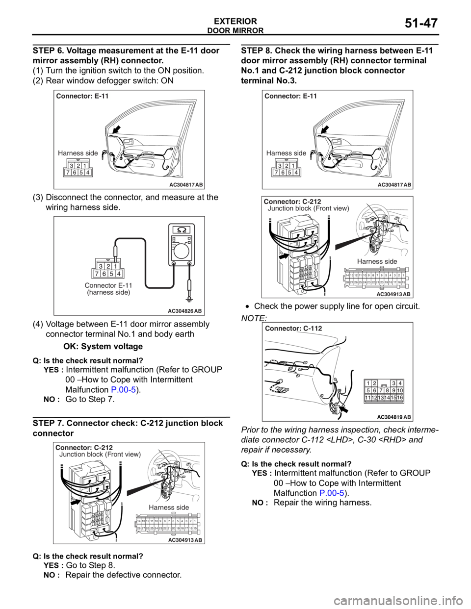
STEP 6. Voltage measurement at the E-11 door
mirror assembly (RH) connector.
(1) Turn the ignition switch to the ON position.
(2) Rear window defogger switch: ON
AC304817
Connector: E-11Harness side
AB
(3) D isconn ect t he co nnector , an d me asure at the
wiring harn e ss side.
AC304826
Connector E-11(harness side)
AB
(4) V olt a g e between E-1 1 door mirror assembly
co nnector termina l No.1 a nd bod y ea rth
OK: System vo lt age
Q: Is the check result normal?
YES : Intermittent ma lfun ctio n (Refer to GROUP
00
− Ho w t o Cope wit h Intermitte nt
Malfunction
P.00-5).
NO : Go to S t ep 7.
STEP 7. Co nnector ch eck: C-212 junction block
connecto
r
AC304913
21716151718
201912345
623 222425282627981011141213
Connector: C-212
Harness side
AB
Junction block (Front view)
Q : Is the check result normal?
YES : Go to S t ep 8.
NO : Repa ir the defective connector .
STEP 8 . Check the wiring harness b e twee n E-1 1
door mirror assem
bly (RH) conne ctor terminal
No.
1 and C-21 2 junctio n block connec tor
terminal No.3
.
AC304817
Connector: E-11
Harness side
AB
AC304913
21716151718
201912345
623 222425282627981011141213
Connector: C-212
Harness side
AB
Junction block (Front view)
•Check th e power supply line fo r open circuit.
NOTE:
AC304819
Connector: C-112
AB
Prior to the wiring harness insp ection, check interme-
diate connector C-1 1 2
rep
a ir if necessary .
Q:Is t h e che c k r esu lt n o rmal?
YES : Intermittent malfun ctio n (Refer to GROUP
00
− Ho w to Cope wit h Intermitte nt
Ma
lfunction
P.00-5).
NO : Repa ir th e wirin g harne ss.