battery specification MITSUBISHI LANCER 2006 Workshop Manual
[x] Cancel search | Manufacturer: MITSUBISHI, Model Year: 2006, Model line: LANCER, Model: MITSUBISHI LANCER 2006Pages: 800, PDF Size: 45.03 MB
Page 65 of 800

CHARGING SYSTEM
ENGINE ELECTRICAL16-3
SERVICE SPECIFICATIONS
M1161000300258
ItemStandard valueLimit
Alternator output line voltage drop (at 30 A) V−maximum 0.3
Regulated voltage ambient
temperature at voltage regulator V−20°C14.2 − 15.4−
20°C13.9 − 14.9−
60°C13.4 − 14.6−
80°C13.1 − 14.5−
Output current−70 % of normal output current
SPECIAL TOOLM1161000600163
ToolNumberNameUse
MB991519Alterna t or test harn e ssChec king th e alt e rnator
("S" te rminal volt age )
ON-VEHICLE SERV ICE
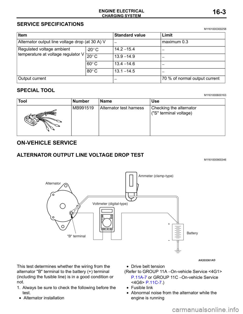
ALTERNA T O R OUTPUT LINE VOL T AGE DROP TEST
M1161 0009 0034 6
AK203361AD
Alternator Ammeter (clamp-type)
Voltmeter (digital-type)
"B" terminal Battery
This test
determine s whethe r the wiring fro m th e
altern
ator "B" termina l to t he batt e ry (+) terminal
(including the
fusible line ) is in a good condition or
not.
1.Always b e su re to check the following b e fore th e
te st.
•Alternator inst allatio n
•Drive belt tension
(Ref er to GROUP 1 1 A − On-veh icle Service <4G1>
P.11A-7 or GROUP 1 1 C − On-vehicle Service
<4G6> P.11C-7.)
•Fusible link
•Abnormal noise from the altern ator while the
eng
ine is ru nning
Page 68 of 800

CHARGING SYSTEM
ENGINE ELECTRICAL16-6
9. Check that the reading on the voltmeter is equal
to the battery voltage.
NOTE: If the voltage is 0 V, the cause is probably
an open circuit in the wire or fusible link between
the alternator "B" terminal and the battery (+) ter
-
minal.
10.Turn the light switch on to turn on headlamps and
then start the engine.
11.Immediately after setting the headlamps to high
beam and turning the heater blower switch to the
high revolution position, increase the engine
speed to 2,500 r/min and read the maximum
current output value displayed on the ammeter.
Limit: 70 % of normal current output
NOTE: .
•For the nominal current output, refer to the
Alternator Specifications.
•Because the current from the battery will soon
drop after the engine is started, the above step
should be carried out as quickly as possible in
order to obtain the maximum current output
value.
•The current output value will depend on the
electrical load and the temperature of the
alternator body.
•If the electrical load is small while testing, the
specified level of current may not be output
even though the alternator is normal. In such
cases, increase the electrical load by leaving
the headlamps turned on for some time to dis
-
charge the battery or by using the lighting sys-
tem in another vehicle, and then test again.
•The specified level of current also may not be
output if the temperature of the alternator body
or the ambient temperature is too high. In such
cases, cool the alternator and then test again.
12.The reading on the ammeter should be above the
limit value. If the reading is below the limit value
and the alternator output wire is normal, remove
the alternator from the engine and check the
alternator.
13.Run the engine at idle after the test.
14.Turn the ignition switch to the "LOCK" (OFF)
position.
15.Remove the tachometer or the M.U.T.-II/III.
16.Disconnect the negative battery cable.
17.Disconnect the ammeter and voltmeter.
18.Connect the negative battery cable.
Page 85 of 800

STARTING SYSTEM
ENGINE ELECTRICAL16-23
STARTER MOTOR ASSEMBLY INSPECTION
M1162001100205
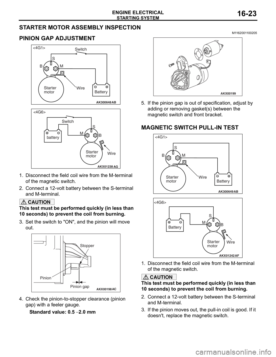
PINION GAP ADJUSTMENT
AK300648AB
<4G1>
Switch
S M
Wire Battery
Starter
motor
B
AKX01238
<4G6>
B
M S
battery Switch
Starter
motorWire
AG
1.
Disco nnect the field coil wire f r om th e M-te rmin al
of the magnet ic switch.
2.Conn ect a 12-volt b a ttery between the S-termina l
an d M-t e rminal.
CAUTION
This test must be performed quickly (in less than
10 seconds) to prevent the coil from burning.
3. Set the switch to "ON", and the pinion will move out.
AKX00198
Stopper
Pinion gap
Pinion
AC
4. Check the pinion-to-stopper clearance (pinion
gap) with a feeler gauge.
Standard value: 0.5 − 2.0 mm
AKX00199
5. If the pinion gap is out of specification, adjust by adding or removing gasket(s) between the
magnetic switch and front bracket.
MAGNETIC SWITCH PULL-IN TEST
AK300649AB
<4G1>
SM
Wire Battery
Starter
motor
B
AKX01242
<4G6>
SB
M
Battery
Starter
motorWire
AF
1. Disconnect the field coil wire from the M-terminal
of the magnetic switch.
CAUTION
This test must be performed quickly (in less than
10 seconds) to prevent the coil from burning.
2. Connect a 12-volt battery between the S-terminal and M-terminal.
3. If the pinion moves out, the pull-in coil is good. If it doesn't, replace the magnetic switch.
Page 86 of 800

STARTING SYSTEM
ENGINE ELECTRICAL16-24
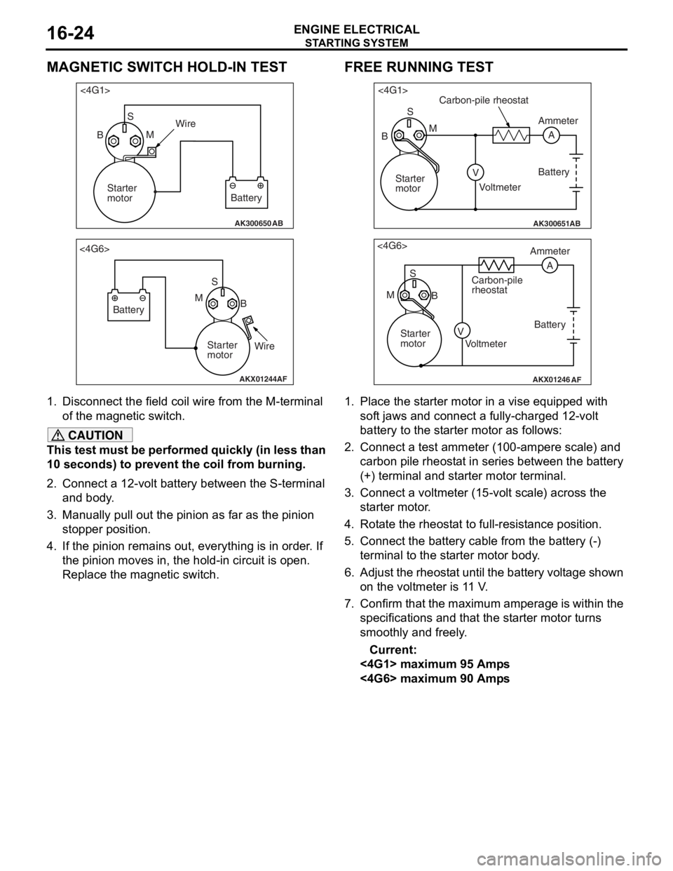
MAGNETIC SWITCH HOLD-IN TEST
AK300650AB
<4G1>S
B MWire
Battery
Starter
motor
AKX01244
<4G6>
SB
M
Battery
Starter
motorWire
AF
1.
Disco nnect the field coil wire f r om th e M-te rmin al
of the magnet ic switch.
CAUTION
This test must be performed quickly (in less than
10 seconds) to prevent the coil from burning.
2. Connect a 12-volt battery between the S-terminal and body.
3. Manually pull out the pinion as far as the pinion stopper position.
4. If the pinion remains out, everything is in order. If
the pinion moves in, the hold-in circuit is open.
Replace the magnetic switch.
FREE RUNNING TEST
AK300651AB
<4G1>
S
A
M
V
B
Carbon-pile rheostat
Battery
Voltmeter Ammeter
Starter
motor
AKX01246
<4G6> S
M B Ammeter
Carbon-pile
rheostat
Battery
Starter
motor Voltmeter
AF
A
V
1. Place the starter motor in a vise equipped with soft jaws and connect a fully-charged 12-volt
battery to the starter motor as follows:
2. Connect a test ammeter (100-ampere scale) and carbon pile rheostat in series between the battery
(+) terminal and starter motor terminal.
3. Connect a voltmeter (15-volt scale) across the starter motor.
4. Rotate the rheostat to full-resistance position.
5. Connect the battery c able from the battery (-)
terminal to the starter motor body.
6. Adjust the rheostat until the battery voltage shown
on the voltmeter is 11 V.
7. Confirm that the maximum amperage is within the specifications and that the starter motor turns
smoothly and freely.
Current:
<4G1> maximum 95 Amps
<4G6> maximum 90 Amps