horn MITSUBISHI LANCER 2006 Workshop Manual
[x] Cancel search | Manufacturer: MITSUBISHI, Model Year: 2006, Model line: LANCER, Model: MITSUBISHI LANCER 2006Pages: 800, PDF Size: 45.03 MB
Page 395 of 800
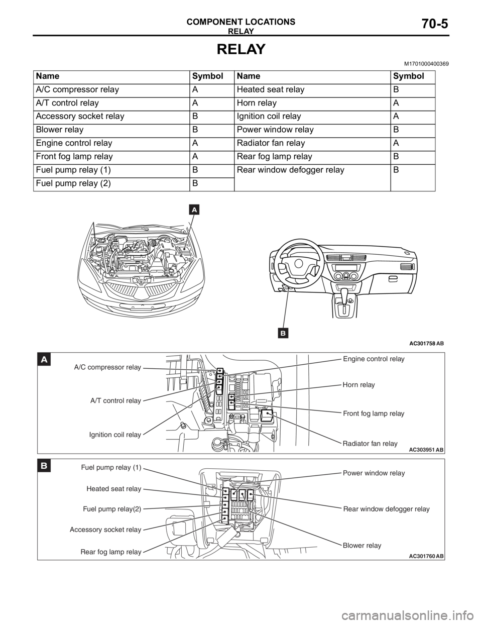
RELAY
COMPONENT LOCATIONS70-5
RELAY
M1701000400369
NameSymbolNameSymbol
A/C compressor relayAHeated seat relayB
A/T control relayAHorn relayA
Accessory socket relayBIgnition coil relayA
Blower relayBPower window relayB
Engine control relayARadiator fan relayA
Front fog lamp relayARear fog lamp relayB
Fuel pump relay (1)BRear window defogger relayB
Fuel pump relay (2)B
AC301758AB
A
B
AC303951AB
A/C compressor relayEngine control relay
Horn relay
Front fog lamp relay
Radiator fan relay
A/T control relay
Ignition coil relayA
AC301760
Fuel pump relay (1) Power window relay
Rear window defogger relay
Blower relay
Heated seat relay
Fuel pump relay(2)
Accessory socket relay
Rear fog lamp relayAB
B
Page 398 of 800
AC206644AD
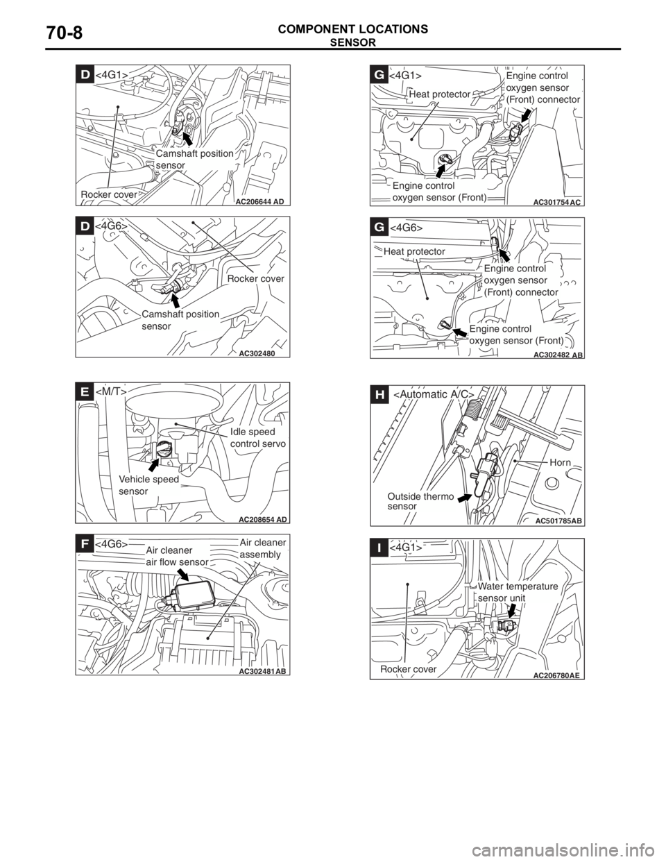
Camshaft position
sensor
D<4G1>
Rocker cover
AC302480AB
D
Camshaft position
sensor
Rocker cover
<4G6>
AC208654
AD
E
Vehicle speed
sensor
Idle speed
control servo
AC302481AB
FAir cleaner
assembly<4G6>Air cleaner
air flow sensor
AB
AC301754
G<4G1>
AC
Heat protector
Engine control
oxygen sensor (Front)
Engine control
oxygen sensor
(Front) connector
AC302482
G
AB
Heat protector
<4G6>
Engine control
oxygen sensor
(Front) connector
Engine control
oxygen sensor (Front)
AC501785AB
H
Horn
Outside thermo
sensor
AC206780 AE
I
Rocker cover
<4G1>
Water temperature
sensor unit
SE
NSOR
COMPONENT LOCA TIONS70-8
Page 416 of 800
ENGINE COMPARTMENT
CONFIGURATION DIAGRAMS80-6
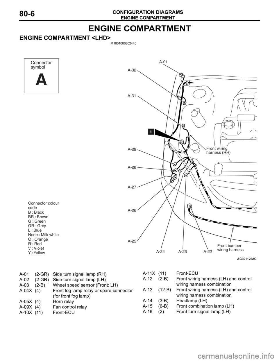
ENGINE COMPARTMENT
ENGINE COMPARTMENT
AC301123
Front wiring
harness (RH)
A-01
A-32
A-31
A-29
A-28
A-27
A-26
A-25 A-23
A-24 A-22
AC
1
Front bumper
wiring harness
Connector colour
code
B : Black
BR : Brown
G : Green
GR : Grey
L : Blue
None : Milk white
O : Orange
R : Red
V : Violet
Y : Yellow
Connector
symbol
A
A-01(2-GR)Side turn signal lamp (RH)
A-02(2-GR)Side turn signal lamp (LH)
A-03(2-B)Wheel speed sensor (Front: LH)
A-04X(4)Front fog lamp relay or spare connector
(for front fog lamp)
A-05X(4)Horn relay
A-09X(4)Fan control relay
A-10X(11)Front-ECU
A-11X(11)Front-ECU
A-12(2-B)Front wiring harness (LH) and control
wiring harness combination
A-13(12-B)Front wiring harness (LH) and control
wiring harness combination
A-14(3-B)Headlamp (LH)
A-15(6-B)Front combination lamp (LH)
A-16(2)Front turn signal lamp (LH)
Page 417 of 800
AC502048AB
A-02A-03
A-04X
A-05X
A-09X
A-10X
A-11X
A-12
A-13
A-14
A-15
A-16
A-17
A-18
A-19
A-20
A-21 Front wiring
harness
(LH)
12
A-33
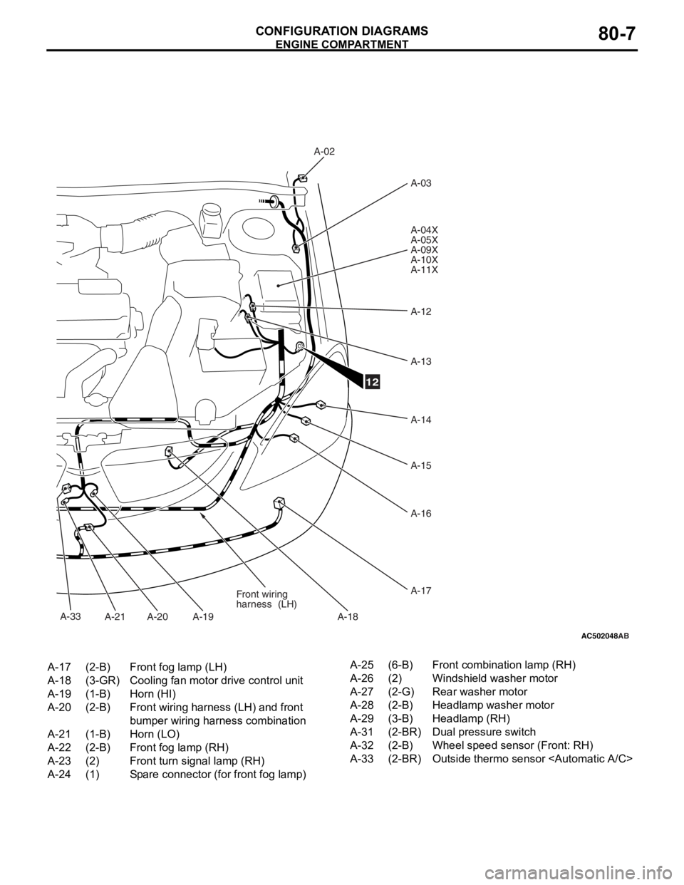
A-17(2-B)Front fog lamp (LH)
A-18(3-GR)Cooling fan motor drive control unit
A-19(1-B)Horn (HI)
A-20(2-B)Front wiring harness (LH) and front
bumper wiring harness combination
A-21(1-B)Horn (LO)
A-22(2-B)Front fog lamp (RH)
A-23(2)Front turn signal lamp (RH)
A-24(1)Spare connector (for front fog lamp)
A-25(6-B)Front combination lamp (RH)
A-26(2)Windshield washer motor
A-27(2-G)Rear washer motor
A-28(2-B)Headlamp washer motor
A-29(3-B)Headlamp (RH)
A-31(2-BR)Dual pressure switch
A-32(2-B)Wheel speed sensor (Front: RH)
A-33(2-BR)Outside thermo sensor
ENGINE COMP AR TMEN T
CONF IGURA TION D I A G RA MS80-7
Page 418 of 800
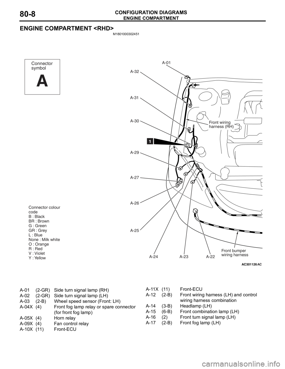
ENGINE COMPARTMENT
CONFIGURATION DIAGRAMS80-8
ENGINE COMPARTMENT
M1801000302451
AC301126
Front wiring
harness (RH)
A-01
A-32
A-31
A-29 A-30
A-27
A-26
A-25 A-23
A-24 A-22
AC
1
Front bumper
wiring harness
Connector colour
code
B : Black
BR : Brown
G : Green
GR : Grey
L : Blue
None : Milk white
O : Orange
R : Red
V : Violet
Y : Yellow
Connector
symbol
A
A-01(2-GR)Side turn signal lamp (RH)
A-02(2-GR)Side turn signal lamp (LH)
A-03(2-B)Wheel speed sensor (Front: LH)
A-04X(4)Front fog lamp relay or spare connector
(for front fog lamp)
A-05X(4)Horn relay
A-09X(4)Fan control relay
A-10X(11)Front-ECU
A-11X(11)Front-ECU
A-12(2-B)Front wiring harness (LH) and control
wiring harness combination
A-14(3-B)Headlamp (LH)
A-15(6-B)Front combination lamp (LH)
A-16(2)Front turn signal lamp (LH)
A-17(2-B)Front fog lamp (LH)
Page 419 of 800
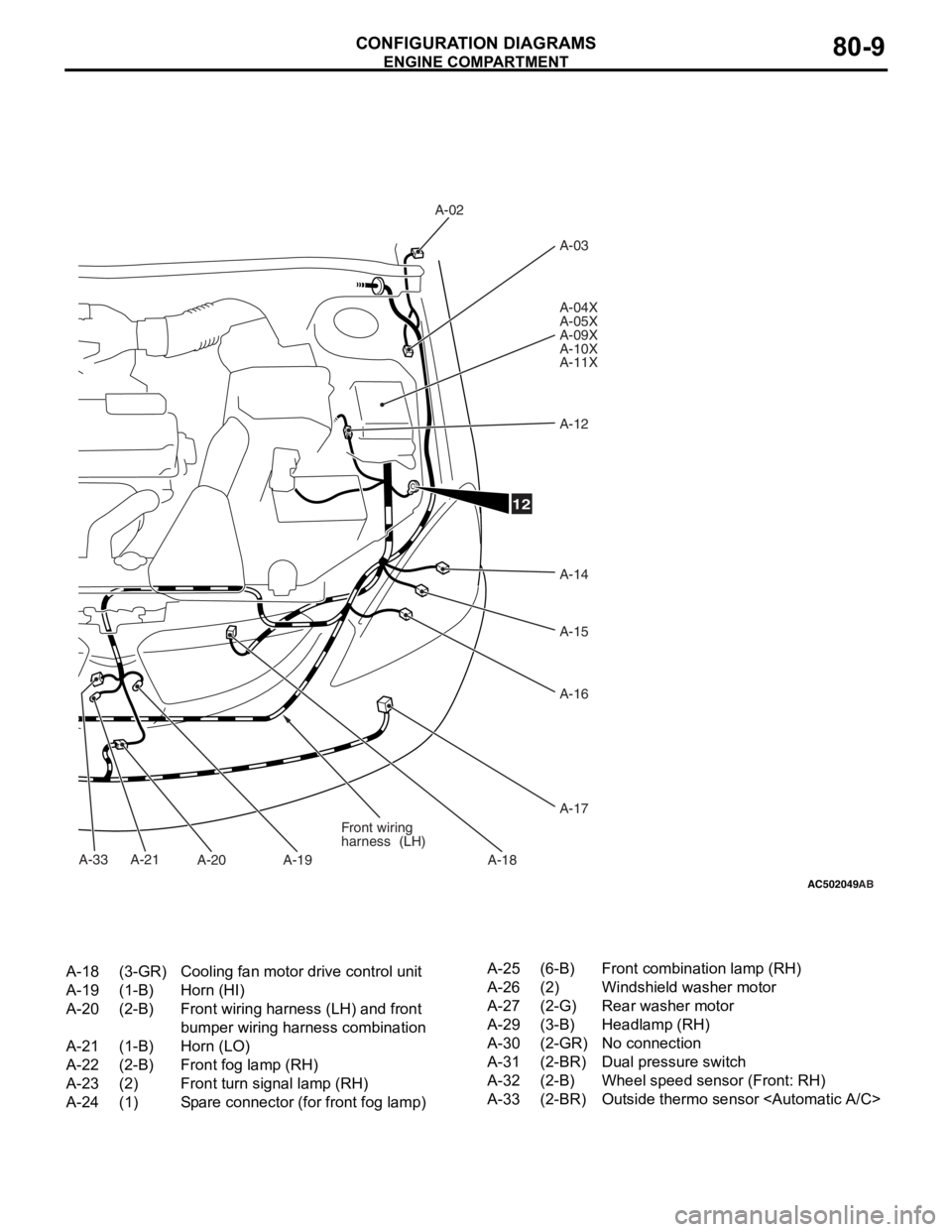
AC502049
A-33
AB
A-02A-03
A-04X
A-05X
A-09X
A-10X
A-11X
A-12
A-14
A-15
A-16
A-17
A-18
A-19
A-20
A-21 Front wiring
harness
(LH)
12
A-18(3-GR)Cooling fan motor drive control unit
A-19(1-B)Horn (HI)
A-20(2-B)Front wiring harness (LH) and front
bumper wiring harness combination
A-21(1-B)Horn (LO)
A-22(2-B)Front fog lamp (RH)
A-23(2)Front turn signal lamp (RH)
A-24(1)Spare connector (for front fog lamp)
A-25(6-B)Front combination lamp (RH)
A-26(2)Windshield washer motor
A-27(2-G)Rear washer motor
A-29(3-B)Headlamp (RH)
A-30(2-GR)No connection
A-31(2-BR)Dual pressure switch
A-32(2-B)Wheel speed sensor (Front: RH)
A-33(2-BR)Outside thermo sensor
ENGINE COMP AR TMEN T
CONF IGURA TION D I A G RA MS80-9
Page 440 of 800
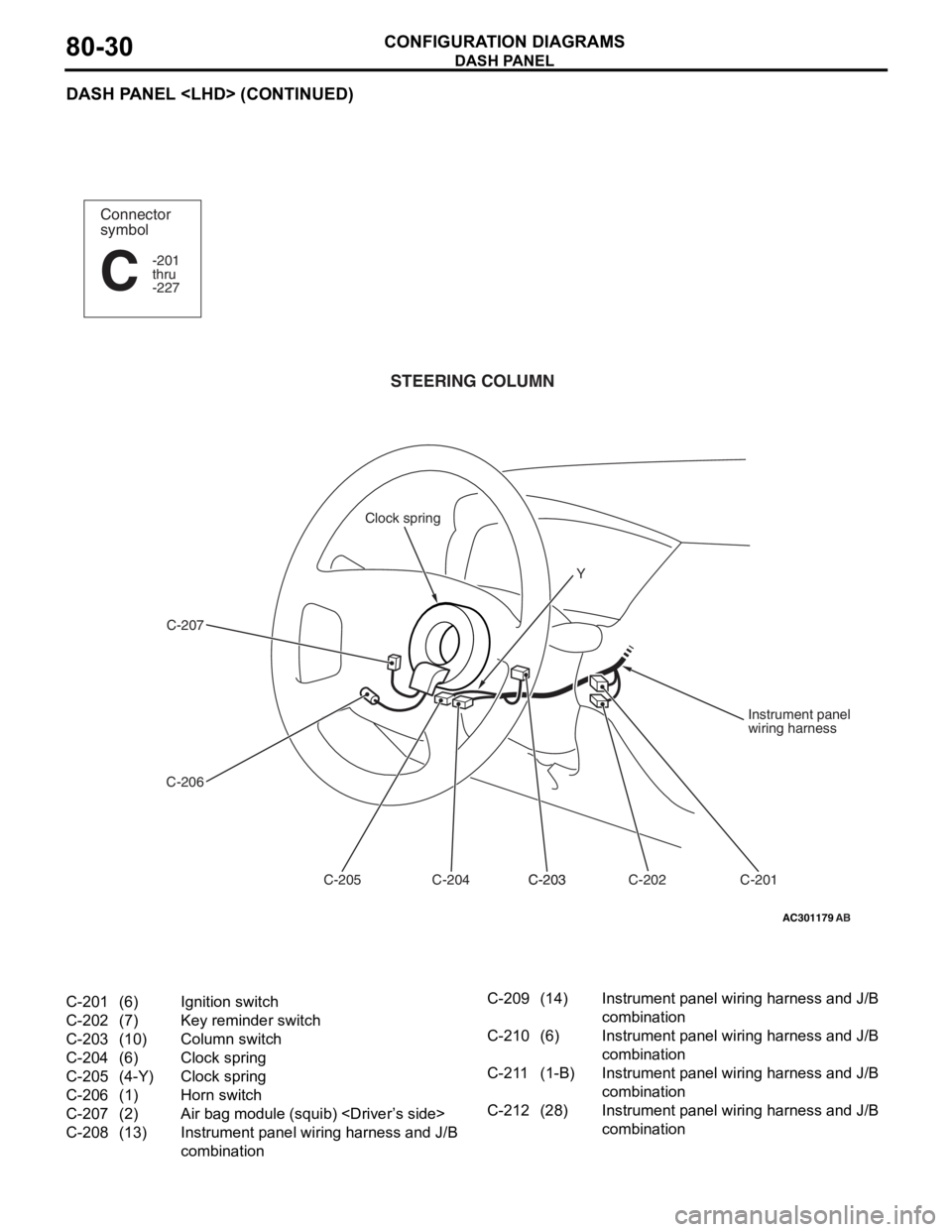
DASH PANEL
CONFIGURATION DIAGRAMS80-30
DASH PANEL
AC301179
Connector
symbol
-201
thru
-227
C
AB
STEERING COLUMN
C-207
C-206 C-201
C-202
C-203C-203
C-204
C-205 Instrument panel
wiring harness
Clock spring
Y
C-201(6)Ignition switch
C-202(7)Key reminder switch
C-203(10)Column switch
C-204(6)Clock spring
C-205(4-Y)Clock spring
C-206(1)Horn switch
C-207(2)Air bag module (squib)
C-208(13)Instrument panel wiring harness and J/B
combination
C-209(14)Instrument panel wiring harness and J/B
combination
C-210(6)Instrument panel wiring harness and J/B
combination
C-211(1-B)Instrument panel wiring harness and J/B
combination
C-212(28)Instrument panel wiring harness and J/B
combination
Page 446 of 800
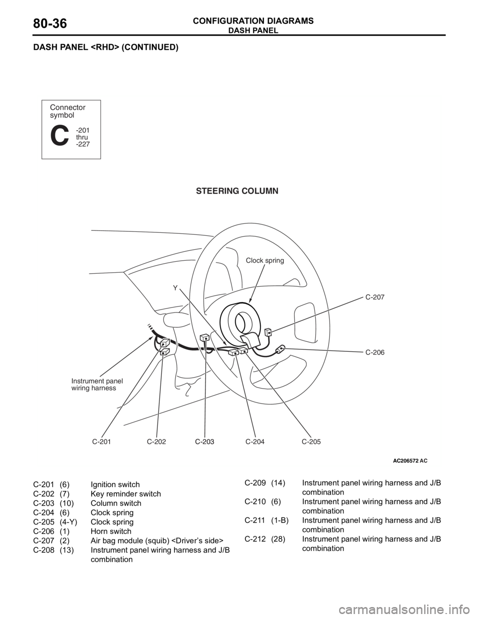
DASH PANEL
CONFIGURATION DIAGRAMS80-36
DASH PANEL
AC206572
Connector
symbol
-201
thru
-227
C
AC
STEERING COLUMN
C-207
C-206
C-205
C-204
C-203C-203
C-202
C-201
Instrument panel
wiring harness
Clock spring
Y
C-201(6)Ignition switch
C-202(7)Key reminder switch
C-203(10)Column switch
C-204(6)Clock spring
C-205(4-Y)Clock spring
C-206(1)Horn switch
C-207(2)Air bag module (squib)
C-208(13)Instrument panel wiring harness and J/B
combination
C-209(14)Instrument panel wiring harness and J/B
combination
C-210(6)Instrument panel wiring harness and J/B
combination
C-211(1-B)Instrument panel wiring harness and J/B
combination
C-212(28)Instrument panel wiring harness and J/B
combination
Page 466 of 800
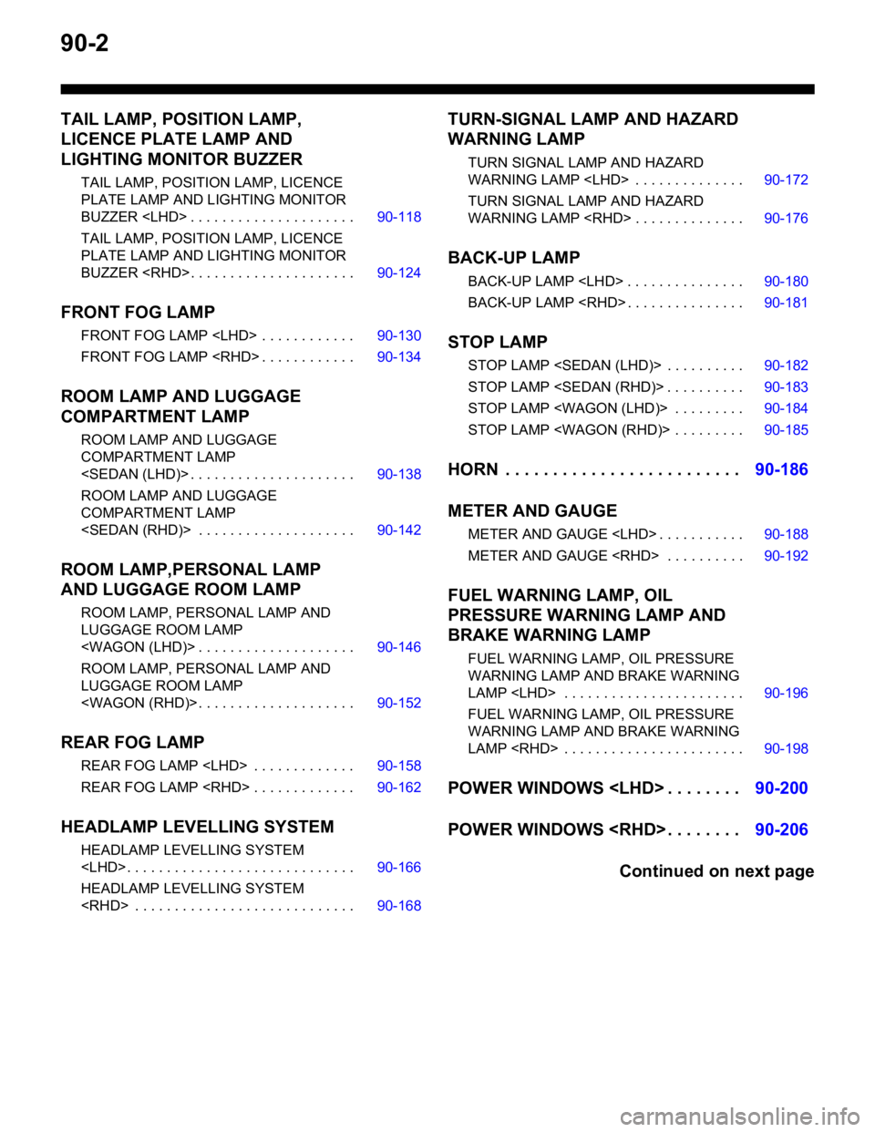
90-2
TAIL LAMP, POSITION LAMP,
LICENCE PLATE LAMP AND
LIGHTING MONITOR BUZZER
TAIL LAMP, POSITION LAMP, LICENCE
PLATE LAMP AND LIGHTING MONITOR
BUZZER
TAIL LAMP, POSITION LAMP, LICENCE
PLATE LAMP AND LIGHTING MONITOR
BUZZER
FRONT FOG LAMP
FRONT FOG LAMP
FRONT FOG LAMP
ROOM LAMP AND LUGGAGE
COMPARTMENT LAMP
ROOM LAMP AND LUGGAGE
COMPARTMENT LAMP
ROOM LAMP AND LUGGAGE
COMPARTMENT LAMP
ROOM LAMP,PERSONAL LAMP
AND LUGGAGE ROOM LAMP
ROOM LAMP, PERSONAL LAMP AND
LUGGAGE ROOM LAMP
ROOM LAMP, PERSONAL LAMP AND
LUGGAGE ROOM LAMP
REAR FOG LAMP
REAR FOG LAMP
REAR FOG LAMP
HEADLAMP LEVELLING SYSTEM
HEADLAMP LEVELLING SYSTEM
HEADLAMP LEVELLING SYSTEM
TURN-SIGNAL LAMP AND HAZARD
WARNING LAMP
TURN SIGNAL LAMP AND HAZARD
WARNING LAMP
TURN SIGNAL LAMP AND HAZARD
WARNING LAMP
BACK-UP LAMP
BACK-UP LAMP
BACK-UP LAMP
STOP LAMP
STOP LAMP
STOP LAMP
STOP LAMP
STOP LAMP
HORN . . . . . . . . . . . . . . . . . . . . . . . . .90-186
METER AND GAUGE
METER AND GAUGE
METER AND GAUGE
FUEL WARNING LAMP, OIL
PRESSURE WARNING LAMP AND
BRAKE WARNING LAMP
FUEL WARNING LAMP, OIL PRESSURE
WARNING LAMP AND BRAKE WARNING
LAMP
FUEL WARNING LAMP, OIL PRESSURE
WARNING LAMP AND BRAKE WARNING
LAMP
POWER WINDOWS
POWER WINDOWS
Continued on next page
Page 482 of 800

CENTRALIZED JUNCTION
CIRCUIT DIAGRAMS90-18
CENTRALIZED JUNCTION
M1901000301477
FUSIBLE LINK AND FUSE
ENGINE COMPARTMENT
No.Power supply circuitNameRated
capacity (A)Housing
colourLoad circuit
1Battery/ Alternator
(Fusible link No.26)Fusible
link60YellowFuse No.15, 16, 18, 19, 20 (in junction
block) circuit
250RedFan controller
360YellowABS-ECU
440GreenIgnition switch circuit
530PinkPower window main switch and power
window sub switch
6Fuse15BlueFront fog lamp, front fog lamp
indicator lamp, front fog lamp relay
and spare connector (for front fog
lamp)
710RedHorn relay and horn
820YellowAir cleaner air flow sensor, camshaft
position sensor, emission solenoid
valve (EGR system), emission
solenoid valve (purge control system),
engine-A/T-ECU, engine-ECU, engine
control oxygen sensor, engine control
relay, engine crank angle sensor, fan
control relay, fuel injector, ignition coil
relay, immobilizer-ECU and throttle
body idle speed control servo
910RedA/C compressor
1015BlueABS-ECU, engine-A/T-ECU, high
mount stop lamp and rear combination
lamp
1115BlueAccessory socket
127.5BrownAlternator
1310RedETACS-ECU, front turn signal lamp,
rear combination lamp, side turn
signal lamp and turn signal indicator
lamp
1420YellowA/T control solenoid valve assembly
and engine-A/T-ECU
1515BlueFuel pump
16Front-ECU
(Headlamp relay: HI)10RedHeadlamp (RH)
1710RedHeadlamp (LH) and high beam
indicator lamp
18Front-ECU
(Headlamp relay: LO)10RedHeadlamp (RH)
1910RedHeadlamp (LH), headlamp assembly
and headlamp levelling switch