component locations MITSUBISHI LANCER 2006 Workshop Manual
[x] Cancel search | Manufacturer: MITSUBISHI, Model Year: 2006, Model line: LANCER, Model: MITSUBISHI LANCER 2006Pages: 800, PDF Size: 45.03 MB
Page 263 of 800
POWER STEERING GEAR BOX AND LINKAGE
POWER STEERING37-33
Specified sealant: 3M ATD Part No.8661 or
equivalent
2. Secure the threaded portion of the end plug at two places by using a punch.
>>J<< RACK SUPPORT COVER/LOCK
NUT INSTALLATION
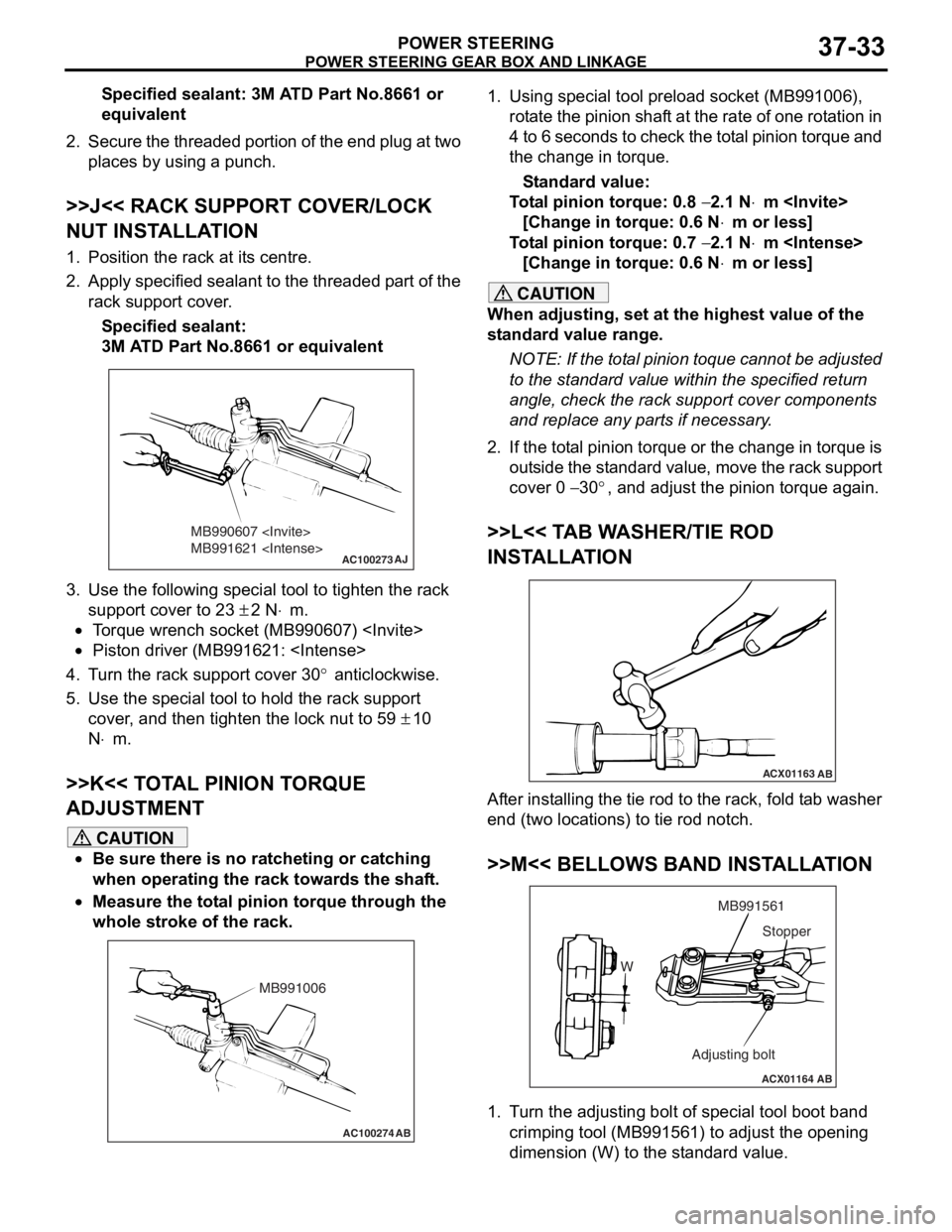
1. Position the rack at its centre.
2. Apply specified sealant to the threaded part of the
rack support cover.
Specified sealant:
3M ATD Part No.8661 or equivalent
AC100273
MB990607
MB991621
AJ
3.Use the fo llo wing special to ol to tigh ten the rack
suppor t cover to 2 3
± 2 N⋅m.
•To rque wren ch socket (MB990607 )
•Piston driver (MB9916 21:
4.T u rn the rack suppo rt cover 30° anticlockwise .
5.Use the special tool to hold the r a ck sup port
cove r , and t hen tighten the lock nut to 59
± 10
N
⋅m.
>>K<< T O T A L PINION T O RQUE
ADJUSTMENT
CAUTION
•Be sure there is no ratcheting or catching
when operating the rack towards the shaft.
•
AC100274 AB
MB991006
Measure the total pinion torque through the
whole stroke of the rack.
1. Using special tool preload socket (MB991006),
rotate the pinion shaft at the rate of one rotation in
4 to 6 seconds to check the total pinion torque and
the change in torque.
Standard value:
Total pinion torque: 0.8 − 2.1 N⋅m
[Change in torque: 0.6 N
⋅m or less]
Total pinion torque: 0.7 − 2.1 N⋅m
[Change in torque: 0.6 N
⋅m or less]
CAUTION
When adjusting, set at the highest value of the
standard value range.
NOTE: If the total pinion toque cannot be adjusted
to the standard value within the specified return
angle, check the rack support cover components
and replace any parts if necessary.
2. If the total pinion torque or the change in torque is outside the standard value, move the rack support
cover 0
− 30°, and adjust the pinion torque again.
>>L<< TAB WASHER/TIE ROD
INSTALLATION
ACX01163 AB
After installing the tie rod to the rack, fold tab washer
end (two locations) to tie rod notch.
>>M<< BELLOWS BAND INSTALLATION
ACX01164 AB
W MB991561
Adjusting bolt Stopper
1. Turn the adjusting bolt of special tool boot band
crimping tool (MB991561) to adjust the opening
dimension (W) to the standard value.
Page 392 of 800
ECU
COMPONENT LOCATIONS70-2
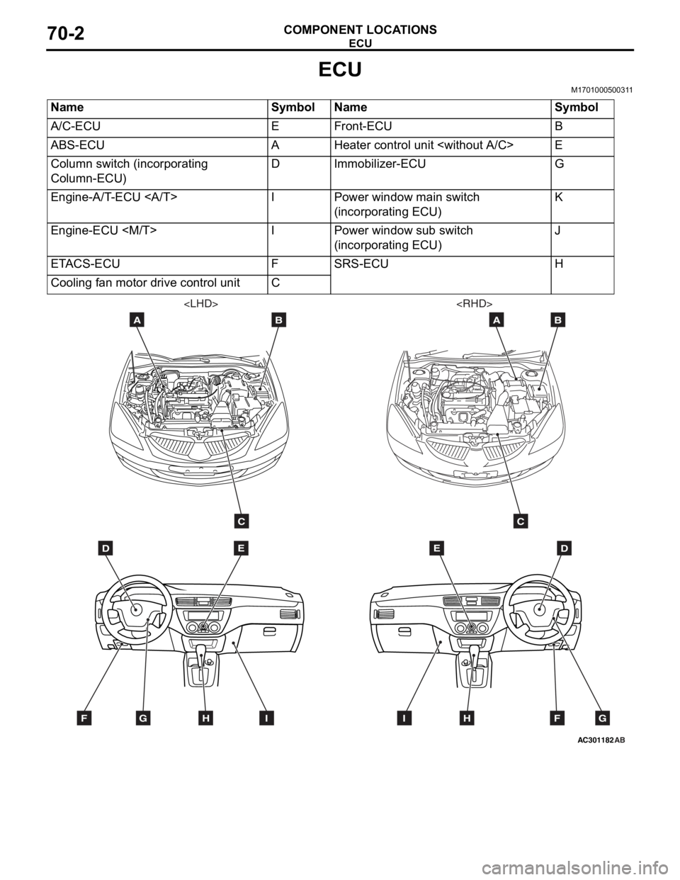
ECU
M1701000500311
NameSymbolNameSymbol
A/C-ECUEFront-ECUB
ABS-ECUAHeater control unit
Column switch (incorporating
Column-ECU)DImmobilizer-ECUG
Engine-A/T-ECU IPower window main switch
(incorporating ECU)K
Engine-ECU
(incorporating ECU)J
ETACS-ECUFSRS-ECUH
Cooling fan motor drive control unitC
AC301182
DE
AB
C
FGHI
AB
DE
AB
C
FGHI
Page 395 of 800
RELAY
COMPONENT LOCATIONS70-5
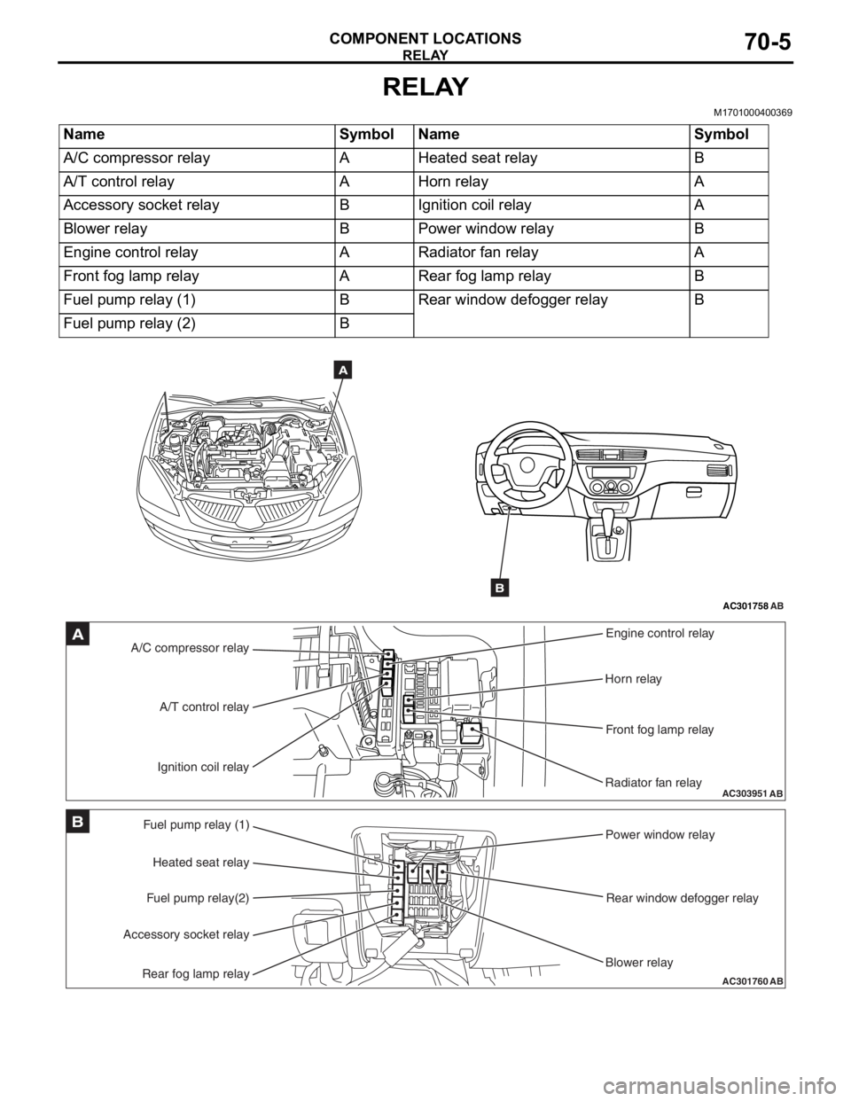
RELAY
M1701000400369
NameSymbolNameSymbol
A/C compressor relayAHeated seat relayB
A/T control relayAHorn relayA
Accessory socket relayBIgnition coil relayA
Blower relayBPower window relayB
Engine control relayARadiator fan relayA
Front fog lamp relayARear fog lamp relayB
Fuel pump relay (1)BRear window defogger relayB
Fuel pump relay (2)B
AC301758AB
A
B
AC303951AB
A/C compressor relayEngine control relay
Horn relay
Front fog lamp relay
Radiator fan relay
A/T control relay
Ignition coil relayA
AC301760
Fuel pump relay (1) Power window relay
Rear window defogger relay
Blower relay
Heated seat relay
Fuel pump relay(2)
Accessory socket relay
Rear fog lamp relayAB
B
Page 396 of 800
SENSOR
COMPONENT LOCATIONS70-6
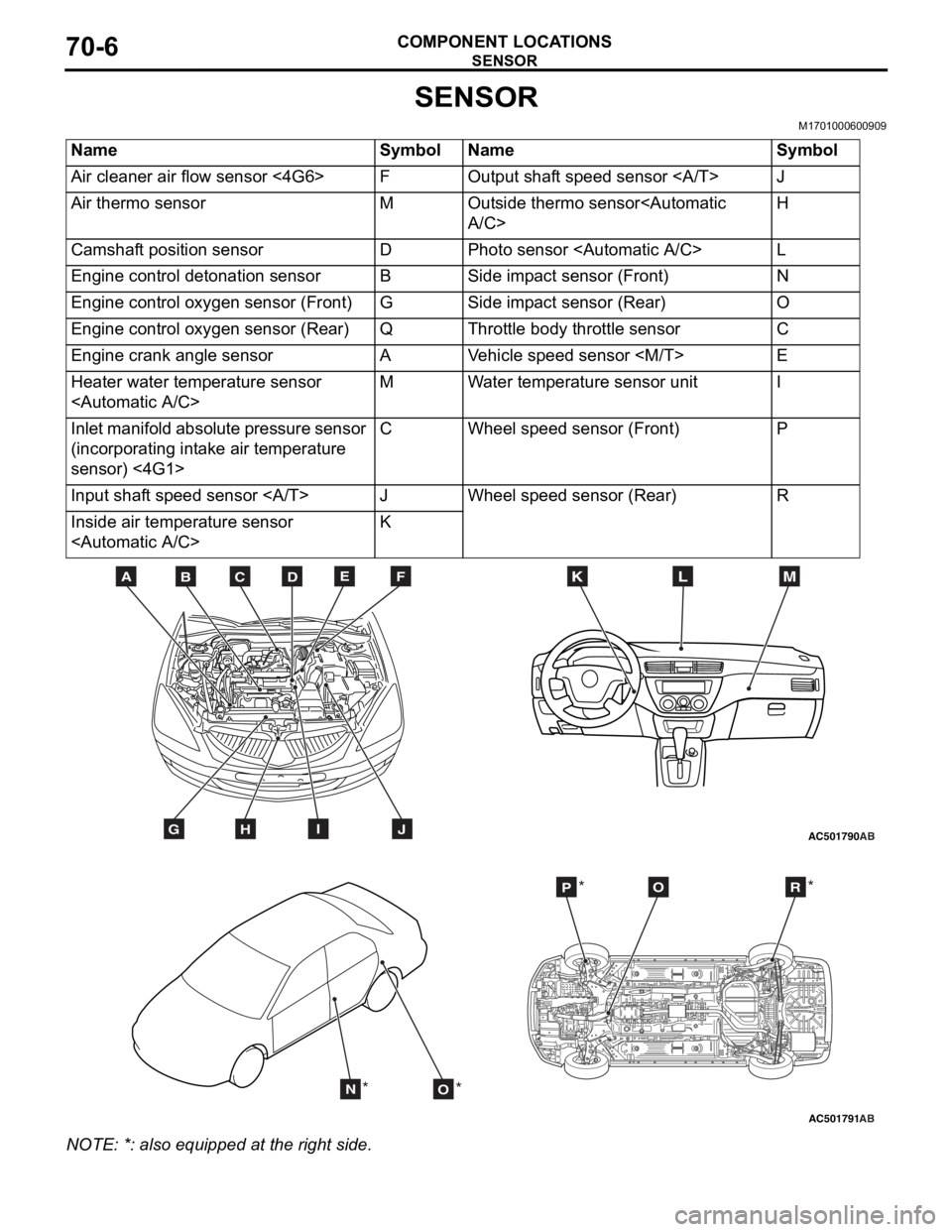
SENSOR
M1701000600909
NameSymbolNameSymbol
Air cleaner air flow sensor <4G6>FOutput shaft speed sensor J
Air thermo sensorMOutside thermo sensor
Camshaft position sensorDPhoto sensor
Engine control detonation sensorBSide impact sensor (Front)N
Engine control oxygen sensor (Front)GSide impact sensor (Rear)O
Engine control oxygen sensor (Rear)QThrottle body throttle sensorC
Engine crank angle sensorAVehicle speed sensor
Heater water temperature sensor
Inlet manifold absolute pressure sensor
(incorporating intake air temperature
sensor) <4G1>CWheel speed sensor (Front)P
Input shaft speed sensor JWheel speed sensor (Rear)R
Inside air temperature sensor
AC501790
BDCFEA
GHIJ
MKL
AB
AC501791AB
NO
POR
** *
*
NO
TE: *: also eq uipp ed at t he rig h t side.
Page 401 of 800
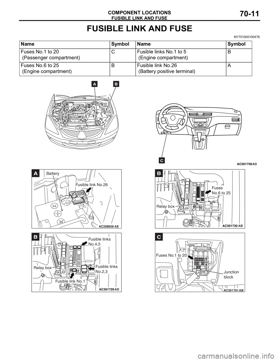
FUSIBLE LINK AND FUSE
COMPONENT LOCATIONS70-11
FUSIBLE LINK AND FUSE
M1701000100476
NameSymbolNameSymbol
Fuses No.1 to 20
(Passenger compartment)
CFusible links No.1 to 5
(Engine compartment)
B
Fuses No.6 to 25
(Engine compartment)
BFusible link No.26
(Battery positive terminal)
A
AC301758AD
AB
C
AC208658AE
A
Fusible link No.26
Battery
AC301729AD
B
Fusible link No.1
Relay box
Fusible links
No.4,5
Fusible links
No.2,3
AC301730
B
AB
Fuses
No.6 to 25
Relay box
AC301761
C
AB
Fuses No.1 to 20Junction
block
Page 402 of 800
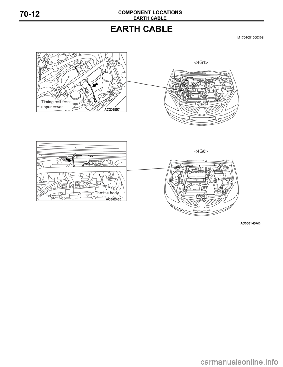
EARTH CABLE
COMPONENT LOCATIONS70-12
EARTH CABLE
M1701001000308
AC303148
AC206557
AC302485
AB
Timing belt front
upper cover
Throttle body
<4G1><4G6>
Page 403 of 800
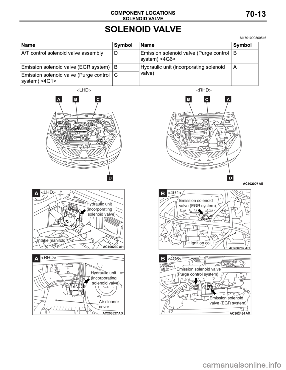
SOLENOID VALVE
COMPONENT LOCATIONS70-13
SOLENOID VALVE
M1701000800516
NameSymbolNameSymbol
A/T control solenoid valve assemblyDEmission solenoid valve (Purge control
system) <4G6>B
Emission solenoid valve (EGR system)BHydraulic unit (incorporating solenoid
valve)A
Emission solenoid valve (Purge control
system) <4G1>C
AC302007
AB
AB
ABC
D
C
D
AC100230
A
AH
Hydraulic unit
(incorporating
solenoid valve)
Intake manifold
AC208527
A
AD
Hydraulic unit
(incorporating
solenoid valve)
Air cleaner
cover
AC206782
<4G1>B
AC
Ignition coil 1
Emission solenoid
valve (EGR system)
AC302484
B
AB
<4G6>
Emission solenoid
valve (EGR system)
Emission solenoid valve
(Purge control system)
Page 405 of 800
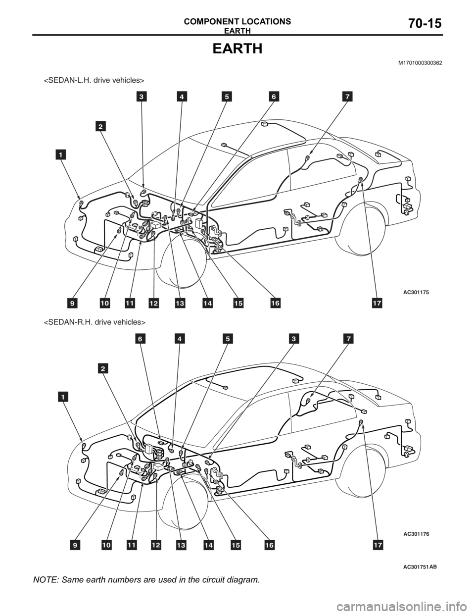
EARTH
COMPONENT LOCATIONS70-15
EARTH
M1701000300362
AC301751
AC301175AC301176
3
2
1
4567
91011121314151617
2
1
4567
91011121314151617
3
AB
NO TE: Same earth numb e rs a r e used in the circu i t diagram.
Page 409 of 800
AC300436AC
15
SRS-ECU
AC208871AC
Junction block16
AC301210
17
AC
Rear seatback
hook (LH)
AC300440
17
AC
Rear
speaker
(LH)
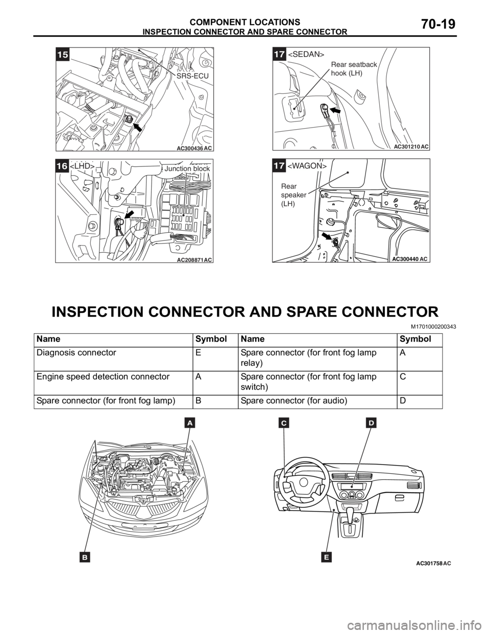
INSPECTION CONN ECT O R AND SP ARE CONNEC T OR
COMPONENT LOCATIONS70-19
IN SPECTION CONNECT OR AND SP ARE CONNECT OR
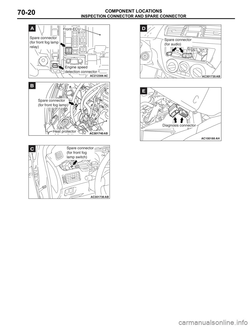
M17010002 0034 3
NameSymbolNameSymbol
Diagnosis connectorESpare connector (for front fog lamp
relay)A
Engine speed detection connectorASpare connector (for front fog lamp
switch)C
Spare connector (for front fog lamp)BSpare connector (for audio)D
AC301758ACB
ADC
E
Page 410 of 800
AC212306
A
AC
Spare connector
(for front fog lamp
relay)
Engine speed
detection connector
Front-ECU
AC301740AB
B
Spare connector
(for front fog lamp)
Heat protector
AC301736AB
Spare connector
(for front fog
lamp switch)C
AC301735AB
D
Spare connector
(for audio)
AC100188AH
Diagnosis connector
E
INSPECTION CONN ECT O R AND SP AR E CONNEC T OR
COMPONENT LOCATIONS70-20