display MITSUBISHI LANCER 2006 Workshop Manual
[x] Cancel search | Manufacturer: MITSUBISHI, Model Year: 2006, Model line: LANCER, Model: MITSUBISHI LANCER 2006Pages: 800, PDF Size: 45.03 MB
Page 66 of 800

CHARGING SYSTEM
ENGINE ELECTRICAL16-4
2. Turn the ignition switch to the "LOCK" (OFF)
position.
3. Disconnect the negative battery cable.
4. Connect a clamp-type DC test ammeter with a
range of 0
− 120 A to the alternator "B" terminal
output wire.
NOTE: The way of disconnecting the alternator
output wire and of connecting the ammeter is pos
-
sibly not found the problem that the output current
is dropping due to the insufficient connection
between terminal "B" and the output wire.
5. Connect a digital-type voltmeter between the
alternator "B" terminal and the battery (+)
terminal. [Connect the (+) lead of the voltmeter to
the "B" terminal and the connect the (-) lead of the
voltmeter to the battery (+) cable].
6. Reconnect the negative battery cable.
7. Connect a tachometer or the M.U.T.-II/III (Refer to
GROUP 11A
− On-vehicle Service − Idle speed
check <4G1>
P.11A-11 or GROUP 11C −
On-vehicle Service − Idle speed check <4G6>
P.11C-11).
8. Leave the hood open.
9. Start the engine.
10.With the engine running at 2,500 r/min, turn the
headlamps and other lamps on and off to adjust
the alternator load so that the value displayed on
the ammeter is slightly above 30 A.
Adjust the engine speed by gradually decreasing
it until the value displayed on the ammeter is 30
A. Take a reading of the value displayed on the
voltmeter at this time.
Limit: maximum 0.3 V
NOTE: When the alternator output is high and the
value displayed on the ammeter does not
decrease until 30 A, set the value to 40 A. Read
the value displayed on the voltmeter at this time.
When the value range is 40 A, the limit is maxi
-
mum 0.4 V.
11.If the value displayed on the voltmeter is above
the limit value, there is probably a malfunction in
the alternator output wire, so check the wiring
between the alternator "B" terminal and the
battery (+) terminal (including fusible link).
If a terminal is not sufficiently tight or if the
harness has become discolored due to
overheating, repair and then test again.
12.After the test, run the engine at idle.
13.Turn off all lamps and the ignition switch.
14.Remove the tachometer or the M.U.T.-II/III.
15.Disconnect the negative battery cable.
16.Disconnect the ammeter and voltmeter.
17.Connect the negative battery cable.
Page 68 of 800

CHARGING SYSTEM
ENGINE ELECTRICAL16-6
9. Check that the reading on the voltmeter is equal
to the battery voltage.
NOTE: If the voltage is 0 V, the cause is probably
an open circuit in the wire or fusible link between
the alternator "B" terminal and the battery (+) ter
-
minal.
10.Turn the light switch on to turn on headlamps and
then start the engine.
11.Immediately after setting the headlamps to high
beam and turning the heater blower switch to the
high revolution position, increase the engine
speed to 2,500 r/min and read the maximum
current output value displayed on the ammeter.
Limit: 70 % of normal current output
NOTE: .
•For the nominal current output, refer to the
Alternator Specifications.
•Because the current from the battery will soon
drop after the engine is started, the above step
should be carried out as quickly as possible in
order to obtain the maximum current output
value.
•The current output value will depend on the
electrical load and the temperature of the
alternator body.
•If the electrical load is small while testing, the
specified level of current may not be output
even though the alternator is normal. In such
cases, increase the electrical load by leaving
the headlamps turned on for some time to dis
-
charge the battery or by using the lighting sys-
tem in another vehicle, and then test again.
•The specified level of current also may not be
output if the temperature of the alternator body
or the ambient temperature is too high. In such
cases, cool the alternator and then test again.
12.The reading on the ammeter should be above the
limit value. If the reading is below the limit value
and the alternator output wire is normal, remove
the alternator from the engine and check the
alternator.
13.Run the engine at idle after the test.
14.Turn the ignition switch to the "LOCK" (OFF)
position.
15.Remove the tachometer or the M.U.T.-II/III.
16.Disconnect the negative battery cable.
17.Disconnect the ammeter and voltmeter.
18.Connect the negative battery cable.
Page 95 of 800

IGNITION SYSTEM
ENGINE ELECTRICAL16-33
SPARK PLUG CHECK AND CLEANING
<4G6>
M1163004300353
CAUTION
When pulling off the spark plug cable from the
plug always hold the cable cap, not the cable.
1. Remove the spark plug cables.
2. Remove the spark plugs.
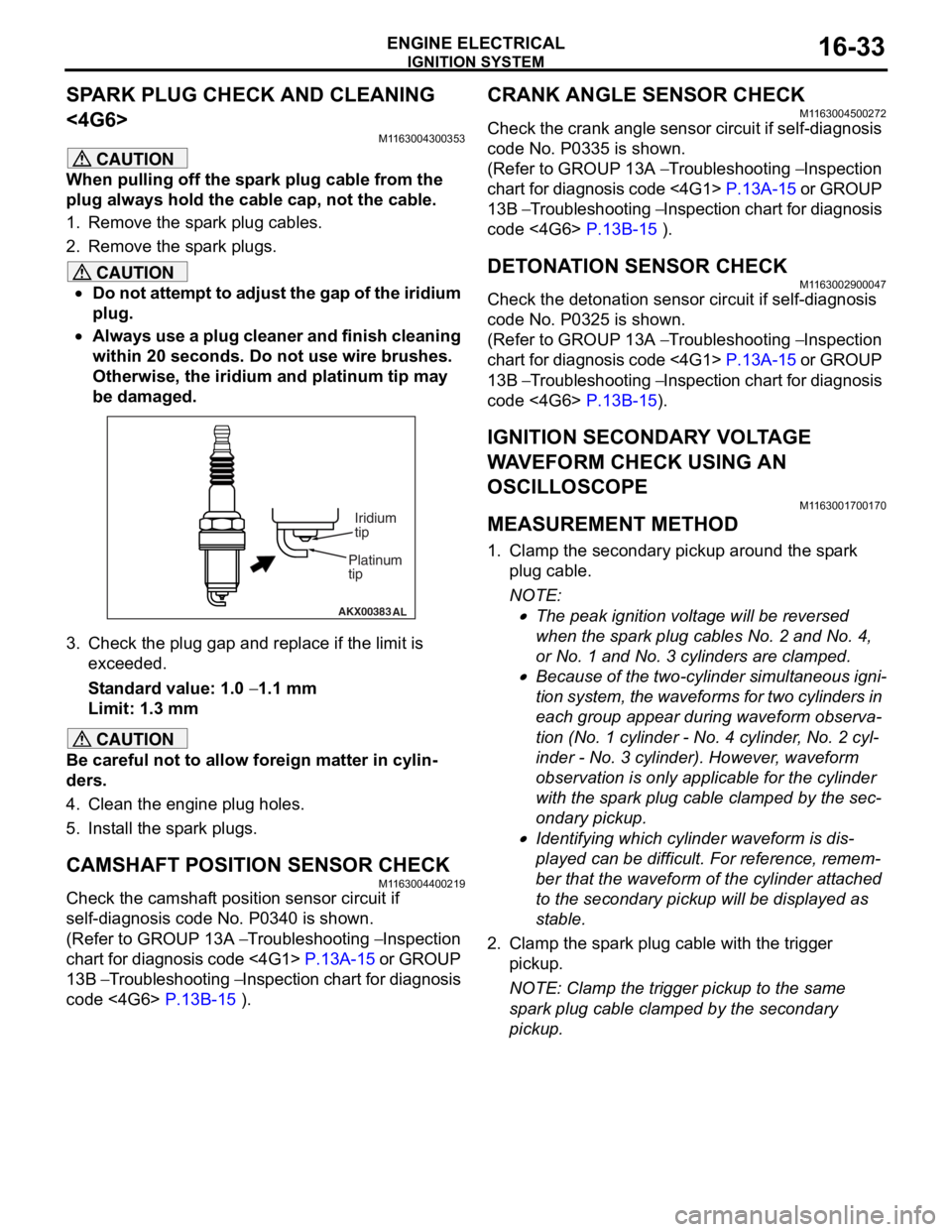
CAUTION
•Do not attempt to adjust the gap of the iridium
plug.
•
AKX00383 AL
Platinum
tipIridium
tip
Always use a plug cleaner and finish cleaning
within 20 seconds. Do not use wire brushes.
Otherwise, the iridium and platinum tip may
be damaged.
3. Check the plug gap and re
place if the limit is
exceeded.
Standard value: 1.0 − 1.1 mm
Limit: 1.3 mm
CAUTION
Be careful not to allow foreign matter in cylin-
ders.
4. Clean the engine plug holes.
5. Install the spark plugs.
CAMSHAFT POSITION SENSOR CHECK
M1163004400219
Check the camshaft position sensor circuit if
self-diagnosis code No. P0340 is shown.
(Refer to GROUP 13A − Troubleshooting − Inspection
chart for diagnosis code <4G1>
P.13A-15 or GROUP
13B − Troubleshooting − Inspection chart for diagnosis
code <4G6>
P.13B-15 ).
CRANK ANGLE SENSOR CHECK
M1163004500272
Check the crank angle sensor circuit if self-diagnosis
code No. P0335 is shown.
(Refer to GROUP 13A − Troubleshooting − Inspection
chart for diagnosis code <4G1>
P.13A-15 or GROUP
13B − Troubleshooting − Inspection chart for diagnosis
code <4G6>
P.13B-15 ).
DETONATION SENSOR CHECKM1163002900047
Check the detonation sensor circuit if self-diagnosis
code No. P0325 is shown.
(Refer to GROUP 13A − Troubleshooting − Inspection
chart for diagnosis code <4G1>
P.13A-15 or GROUP
13B − Troubleshooting − Inspection chart for diagnosis
code <4G6>
P.13B-15).
IGNITION SECONDARY VOLTAGE
WAVEFORM CHECK USING AN
OSCILLOSCOPE
M1163001700170
MEASUREMENT METHOD
1. Clamp the secondary pickup around the spark
plug cable.
NOTE: .
•The peak ignition voltage will be reversed
when the spark plug cables No. 2 and No. 4,
or No. 1 and No. 3 cylinders are clamped.
•Because of the two-cylinder simultaneous igni-
tion system, the waveforms for two cylinders in
each group appear during waveform observa
-
tion (No. 1 cylinder - No. 4 cylinder, No. 2 cyl-
inder - No. 3 cylinder). However, waveform
observation is only applicable for the cylinder
with the spark plug cable clamped by the sec
-
ondary pickup.
•Identifying which cylinder waveform is dis-
played can be difficult. For reference, remem-
ber that the waveform of the cylinder attached
to the secondary pickup will be displayed as
stable.
2. Clamp the spark plug cable with the trigger pickup.
NOTE: Clamp the trigger pickup to the same
spark plug cable clamped by the secondary
pickup.
Page 97 of 800

IGNITION SYSTEM
ENGINE ELECTRICAL16-35
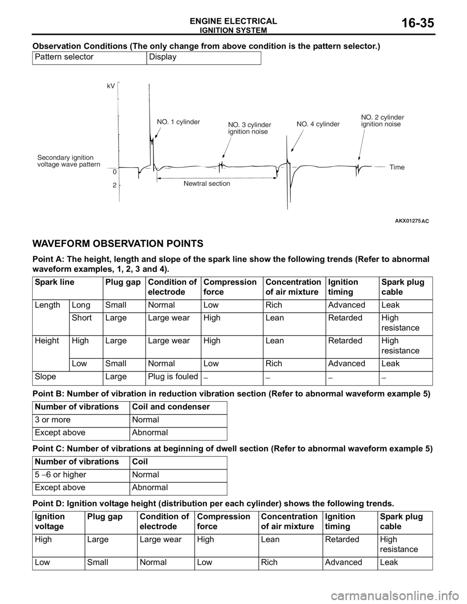
Observation Conditions (The only change from above condition is the pattern selector.)
Pattern selectorDisplay
AKX01275
kV
Secondary ignition
voltage wave pattern 0
2NO. 1 cylinder
NO. 3 cylinder
ignition noise
Newtral section NO. 4 cylinder
NO. 2 cylinder
ignition noise
Time
AC
WA VEFORM OBSER V A T ION POINTS
Point A: The he ight, len g th and s l ope of th e sp a r k line sho w the following trends (Re f er to abnorma l
wave
form exam ples, 1 , 2, 3 a nd 4).
Spark linePlug gapCondition of
electrodeCompression
force Concentration
of air mixtureIgnition
timingSpark plug
cable
LengthLongSmallNormalLowRichAdvancedLeak
ShortLargeLarge wearHigh LeanRetardedHigh
resistance
HeightHighLargeLarge wearHighLeanRetardedHigh
resistance
LowSmallNormalLow RichAdvancedLeak
SlopeLargePlug is fouled−−−−
Point B: Number of v i bra t ion in red uction vi bra t ion sec tion (Refer to a bnormal wavefo r m examp l e 5)
Number of vibrationsCoil and condenser
3 or moreNormal
Except aboveAbnormal
Point C: Number of v i bra t ions a t beginnin g of dwell se ction (Refer to a bnormal wave form exam ple 5)
Number of vibrationsCoil
5 − 6 or higherNormal
Except aboveAbnormal
Point D: Ignition volt a g e height (distribution per each cylinder) s hows the follo wing tren ds.
Ignition
voltagePlug gapCondition of
electrodeCompression
forceConcentration
of air mixtureIgnition
timingSpark plug
cable
HighLargeLarge wearHighLeanRetardedHigh
resistance
LowSmallNormalLowRichAdvancedLeak