gas MITSUBISHI LANCER 2006 Workshop Manual
[x] Cancel search | Manufacturer: MITSUBISHI, Model Year: 2006, Model line: LANCER, Model: MITSUBISHI LANCER 2006Pages: 800, PDF Size: 45.03 MB
Page 8 of 800

GENERAL INFORMATION
ENGINE LUBRICATION12-2
GENERAL INFORMATION
M1121000100357
The lubrication method is a fully force-fed, full-flow fil-
tration type. The engine oil pump is a trochoid type
which is driven by the crankshaft <4G1>.The engine
oil pump is a gear type which is driven by the crank
-
shaft via the balancer timing belt <4G6>.
ENGINE OILS
Health Warning
Prolonged and repeated contact with mineral oil will
result in the removal of natural fats from the skin,
leading to dryness, irritation and dermatitis. In addi
-
tion, used engine oil contains potentially harmful con-
taminants which may cause skin cancer. Adequate
means of skin protection and washing facilities must
be provided.
Recommended Precautions
The most effective precaution is to adapt working
practices which prevent, as far as practicable, the
risk of skin contact with mineral oils, for example by
using enclosed systems for handling used engine oil
and by degreasing components, where practicable,
before handling them. Other precautions:
•Avoid prolonged and repeated contact with oils,
particularly used engine oils.
•Wear protective clothing, including impervious
gloves where practicable.
•Avoid contaminating clothes, particularly under-
pants, with oil.
•Do not put oily rags in pockets, the use of overalls
without pockets will avoid this.
•Do not wear heavily soiled clothing and
oil-impregnated foot-wear. Overalls must be
cleaned regularly and kept separate from per
-
sonal clothing.
•Where there is a risk of eye contact, eye protec-
tion should be worn, for example, chemical gog-
gles or face shields; in addition an eye wash
facility should be provided.
•Obtain first aid treatment immediately for open
cuts and wounds.
•Wash regularly with soap and water to ensure all
oil is removed, especially before meals (skin
cleansers and nail brushes will help). After clean
-
ing, the application of preparations containing
lanolin to replace the natur al skin oils is advised.
•Do not use petrol, kerosine, diesel fuel, gas oil,
thinners or solvents for cleaning skin.
•Use barrier creams, applying them before each
work period, to help the removal of oil from the
skin after work.
•If skin disorders develop, obtain medical advice
without delay.
SERVICE SPECIFICATION
M1121000300232
ItemStandard value
Oil pressure kPaat idle29 or more
at 3,500 r/min294 − 686
LUBRICANT
M1121000400433
ItemSpecification
Engine oil ACEA classificationA1, A2 or A3
Engine oil API classificationSG or higher
Engine oil quantity L4G1Oil filter0.3
To t a l3.3
4G6Oil filter0.3
To t a l4.3
Page 10 of 800
ON-VEHICLE SERVICE
ENGINE LUBRICATION12-4
ON-VEHICLE SERVICE
ENGINE OIL CHECKM1121000900342
ACX00892 AC
Good
Maximum Minimum
<4G1>
AC205268
Maximum MinimumGood
AC
<4G6>
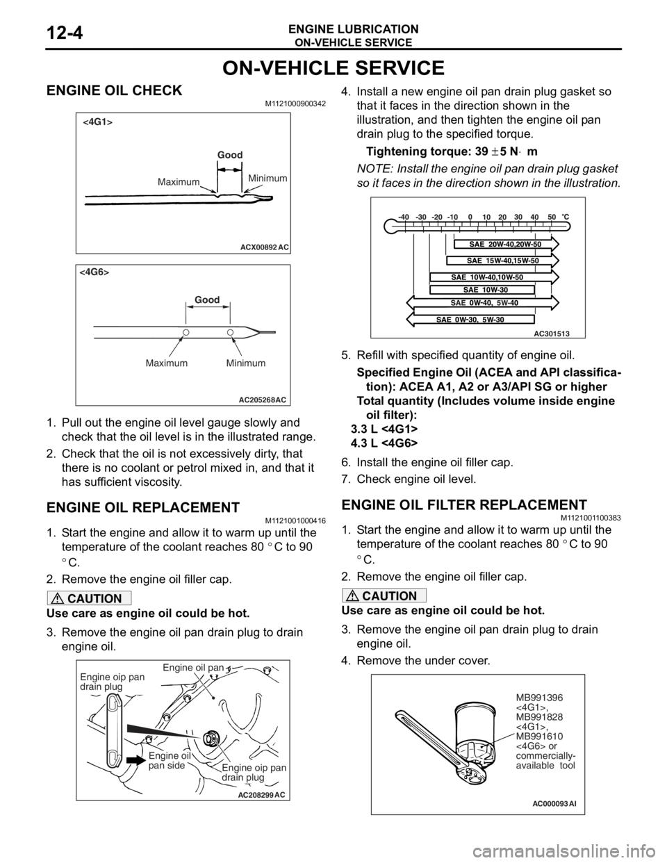
1.
Pull ou t the en gine oil level ga uge slowly and
check tha t the o il level is in t he illustrated range.
2.Check t hat the oil is not excessively dirty , that
th ere is no coolant or p e trol mixed in, and that it
ha s s u f f i c ie nt vi sc osi t y .
ENGINE OIL REPLACEMENT
M1121 0010 0041 6
1.S t art the engin e and allow it to war m up until the
te mpera t ure of the coola n t reaches 80
°C to 90
°C.
2.Remove the en gine oil filler ca p.
CAUTION
Use care as engine oil could be hot.
3. Remove the engine oil pan drain plug to drain
engine oil.
AC208299
Engine oil pan
AC
Engine oip pan
drain plug
Engine oip pan
drain plug
Engine oil
pan side
4. Install a new engine oil pan drain plug gasket so
that it faces in the direction shown in the
illustration, and then tighten the engine oil pan
drain plug to the specified torque.
Tightening torque: 39 ± 5 N⋅m
NOTE: Install the engine oil pan drain plug gasket
so it faces in the direction shown in the illustration.
AC301513
5. Refill with specifi ed quantity of engine oil.
Specified Engine Oil (ACEA and API classifica-
tion): ACEA A1, A2 or A3/API SG or higher
Total quantity (Includes volume inside engine
oil filter):
3.3 L <4G1>
4.3 L <4G6>
6. Install the engine oil filler cap.
7. Check engine oil level.
ENGINE OIL FILTER REPLACEMENTM1121001100383
1. Start the engine and allow it to warm up until the temperature of the coolant reaches 80
°C to 90
°C.
2. Remove the engine oil filler cap.
CAUTION
Use care as engine oil could be hot.
3. Remove the engine oil pan drain plug to drain engine oil.
4. Remove the under cover.
AC000093
MB991396
<4G1>,
MB991828
<4G1>,
MB991610
<4G6> or
commercially-
available tool
AI
Page 41 of 800
WATE R P U M P
ENGINE COOLING14-27
WAT E R P U M P
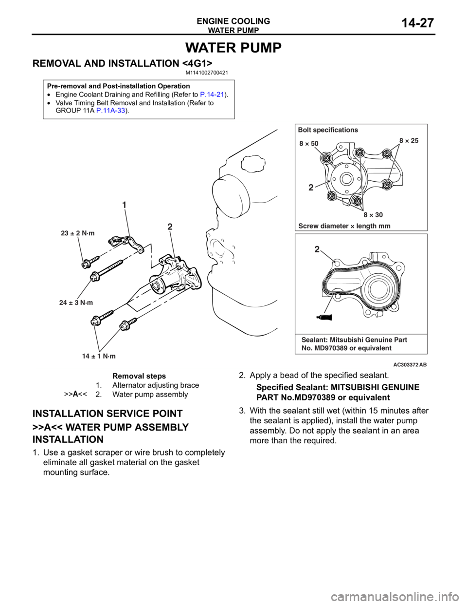
REMOVAL AND INSTALLATION <4G1>M1141002700421
Pre-removal and Post-installation Operation
•Engine Coolant Draining and Refilling (Refer to P.14-21).
•Valve Timing Belt Removal and Installation (Refer to
GROUP 11A P.11A-33).
AC303372
24 ± 3 N·m23 ± 2 N·m
14 ± 1 N·m
1 2
Bolt specifications
Screw diameter × length mm 8 × 50
8 × 308 × 25
AB
2
2
Sealant: Mitsubishi Genuine Part
No. MD970389 or equivalent
Removal steps
1.Alternator adjusting brace
>>A<<2.Water pump assembly
INST ALLA T ION SER VICE POINT
>>A<< WA TER PUMP ASSEMBL Y
INST
ALLA TION
1.Use a gaske t scraper o r wire brush to complet e ly
eliminate all gasket material o n the g a sket
mounting surface.
2. App l y a bead of the specified sealan t.
Specified Sealant: MITSUBISHI GENUINE
P
ART No.MD970 389 or eq uivalen t
3.With the sea l ant still wet (within 1 5 minutes af ter
th e se alant is applied), inst all the wa ter pump
a sse mbly . Do not a pply the sealant in an are a
more th an the required.
Page 42 of 800
WATE R P U M P
ENGINE COOLING14-28
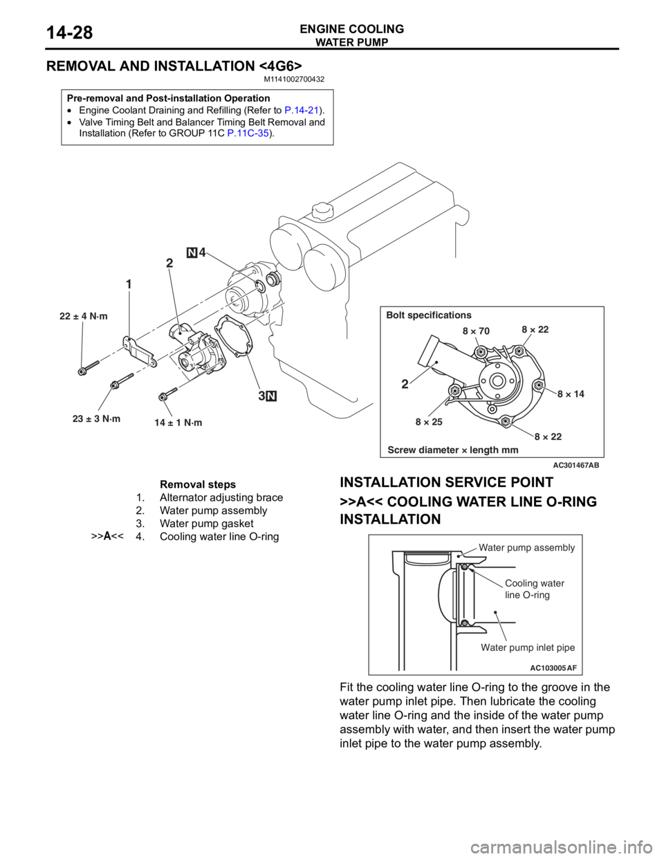
REMOVAL AND INSTALLATION <4G6>
M1141002700432
Pre-removal and Post-installation Operation
•Engine Coolant Draining and Refilling (Refer to P.14-21).
•Valve Timing Belt and Balancer Timing Belt Removal and
Installation (Refer to GROUP 11C
P.11C-35).
AC301467
22 ± 4 N·m23 ± 3 N·m 14 ± 1 N·m
12
3
4
N
N
Bolt specifications
Screw diameter × length mm
8 × 70 8 × 22
8 × 14
8 × 22
8 × 25
2
AB
Removal steps
1.Alternator adjusting brace
2.Water pump assembly
3.Water pump gasket
>>A<<4.Cooling water line O-ring
INST
ALLA T ION SER VICE POINT
>>A<< COOLING WA TER LINE O-RING
INST
ALLA TION
AC103005
Water pump assembly
Cooling water
line O-ring
Water pump inlet pipe
AF
Fit the coo ling water line O-ring to the groove in the
wa
ter pump in let p i pe. T hen lubricate th e co olin g
wa
ter line O-ring and the inside of the wat e r pump
assembly with wa
ter , and then insert the wa ter pu mp
inle
t pip e to the water pu mp asse mbly .
Page 43 of 800
WATER HOSE AND WATER PIPE
ENGINE COOLING14-29
WATER HOSE AND WATER PIPE
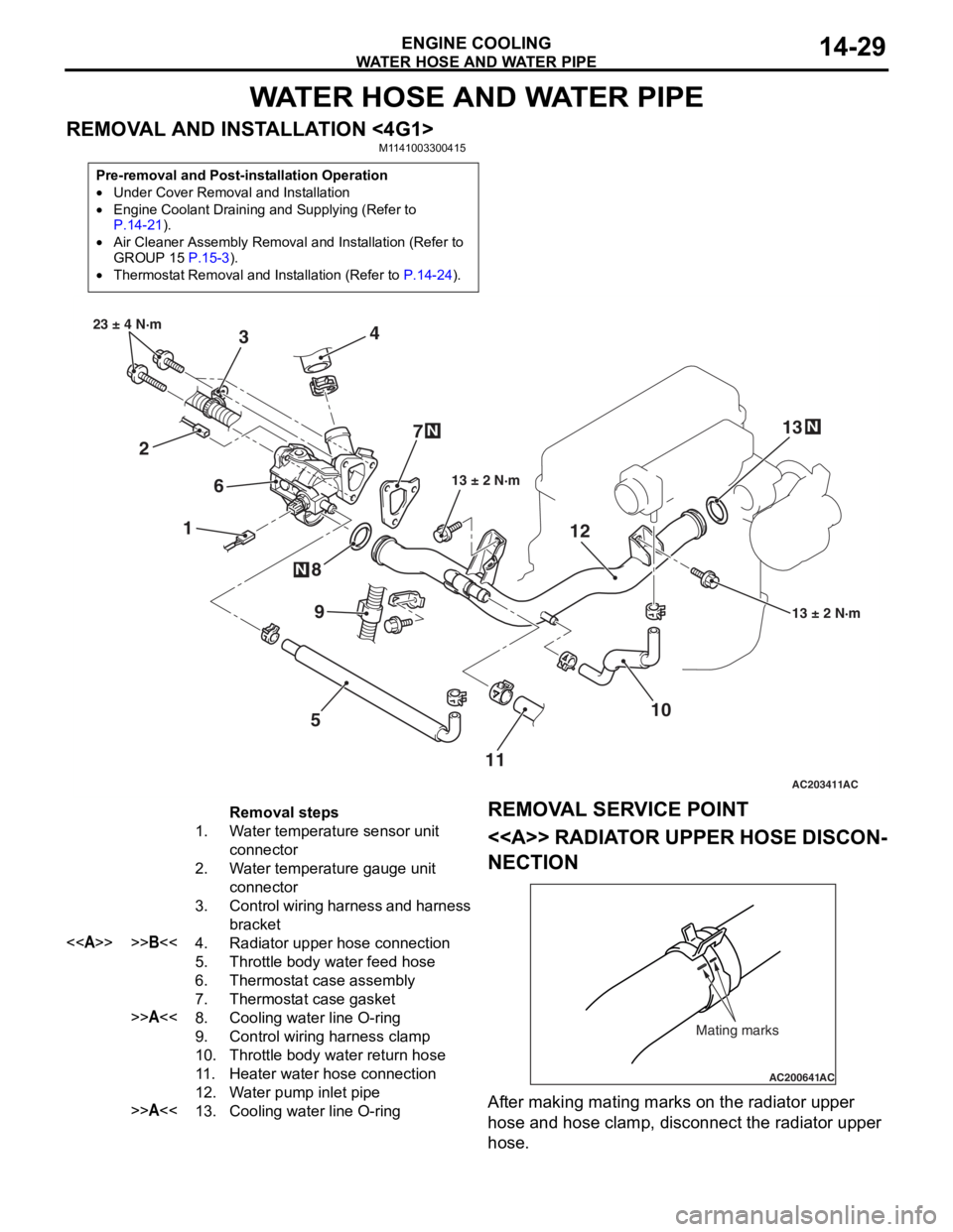
REMOVAL AND INSTALLATION <4G1>M1141003300415
Pre-removal and Post-installation Operation
•Under Cover Removal and Installation
•Engine Coolant Draining and Supplying (Refer to P.14-21).
•Air Cleaner Assembly Removal and Installation (Refer to
GROUP 15 P.15-3).
•Thermostat Removal and Installation (Refer to P.14-24).
AC203411
1
2 3
4
5
6
7
8
10
9
13 ± 2 N·m
23 ± 4 N·m
13 ± 2 N·m
N
N
AC
1112
13
N
Removal steps
1.Water temperature sensor unit
connector
2.Water temperature gauge unit
connector
3.Control wiring harness and harness
bracket
<>>>B<<4.Radiator upper hose connection
5.Throttle body water feed hose
6.Thermostat case assembly
7.Thermostat case gasket
>>A<<8.Cooling water line O-ring
9.Control wiring harness clamp
10.Throttle body water return hose
11 .Heater water hose connection
12.Water pump inlet pipe
>>A<<13.Cooling water line O-ring
REMOV
A L SER VICE POINT
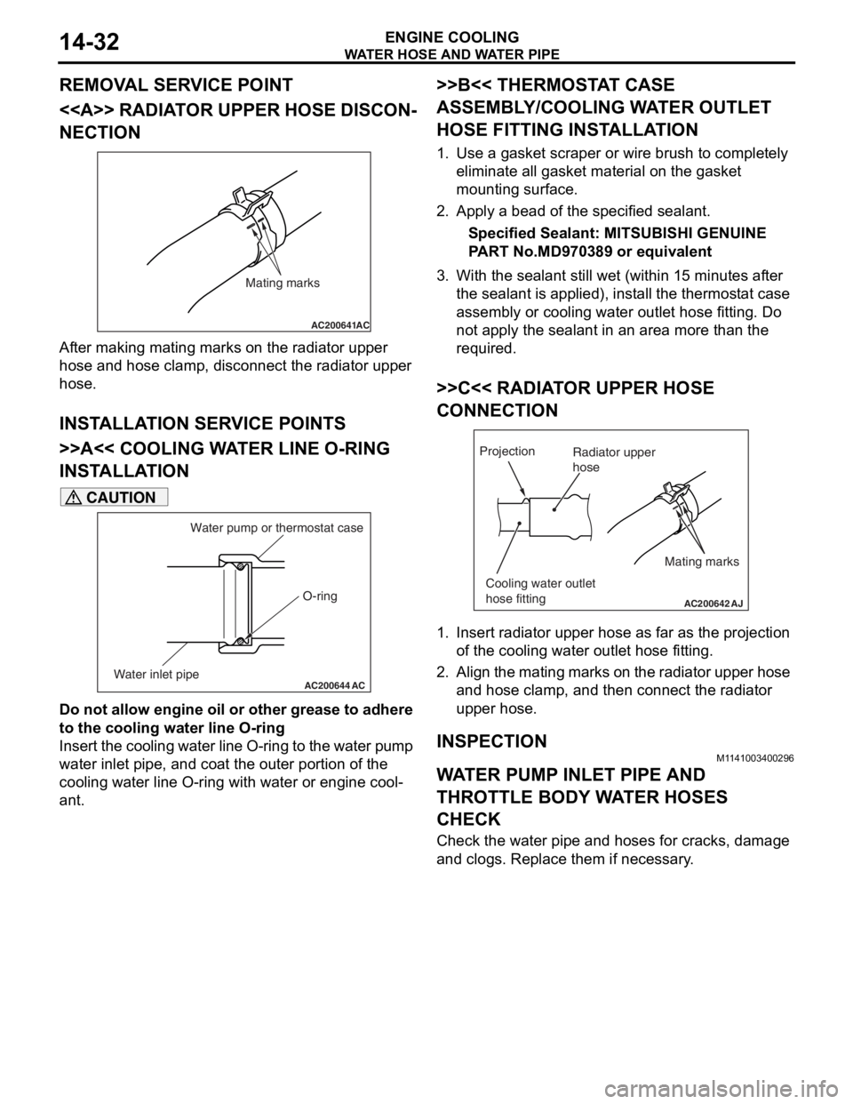
<> RADIAT OR UPPER HOSE DISCON-
NECTION
AC200641AC
Mating marks
After making matin g ma rks on the radia t or upp er
hose
and h o se clamp, disconnect the radia t or upp er
hose
.
Page 46 of 800
Page 54 of 800
AC303619
4.0 ± 1.0 N·m
4.0 ± 1.0 N·m10*
9* 4
1* 5
11
12 ± 1 N·m 9.0 ± 1.0 N·m
9.0 ± 1.0 N·m
AB
12 ± 1 N·m
Clamp
8*
3*
<4G6>
6
7
N
2
8.8 ± 1.0 N·m
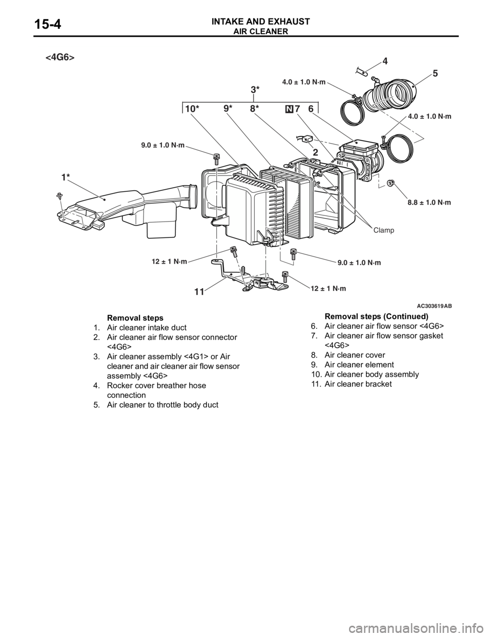
Removal steps
1.Air cleaner intake duct
2.Air cleaner air flow sensor connector
<4G6>
3.Air cleaner assembly <4G1> or Air
cleaner and air cleaner air flow sensor
assembly <4G6>
4.Rocker cover breather hose
connection
5.Air cleaner to throttle body duct
6.Air cleaner air flow sensor <4G6>
7.Air cleaner air flow sensor gasket
<4G6>
8.Air cleaner cover
9.Air cleaner element
10.Air cleaner body assembly
11 .Air cleaner bracket
AIR CLEA NER
INTAKE AN D EXHAU ST15-4
Removal steps (Continued)
Page 55 of 800
INLET MANIFOLD
INTAKE AND EXHAUST15-5
INLET MANIFOLD
REMOVAL AND INSTALLATION <4G1>M1151003000749
Pre-removal Operation
•Fuel Line Pressure Reduction (Refer to GROUP 13A -
On-vehicle Service
P.13A-372).
•Engine Coolant Draining (Refer to GROUP 14 - On-vehi-
cle Service P.14-21).
•Strut Tower Bar Removal (Refer to GROUP 42 P.42-9).
•Throttle Body Assembly Re moval (Refer to GROUP 13A
P.13A-383).
•Fuel Delivery Pipe and Fuel Injector Assembly Removal
(Refer to GROUP 13A
P.13A-381).
Post-installation Operation
•Fuel Delivery Pipe and Fuel Injector Assembly Installation
(Refer to GROUP 13A
P.13A-381).
•Throttle Body Assembly Inst allation (Refer to GROUP
13A
P.13A-383).
•Strut Tower Bar Installati on (Refer to GROUP 42 P.42-9).
•Engine Coolant Supplying (Refer to GROUP 14 - On-vehi-
cle Service P.14-21).
•Accelerator Cable Adjustment (Refer to GROUP 17 -
On-vehicle Service
P.17-2).
•Fuel Leak Check
AC303642AB
15
36
5
4 12
10
7
1
2
11
9 13
14
21 ± 4 N·m
9.0 ± 1.0 N·m
9.0 ± 1.0 N·m
18 ± 2 N·m
18 ± 2 N·m 18 ± 2 N·m
5.0 ± 1.0 N·m
31 ± 3 N·m
49 ± 9 N·m
N
N
N
8
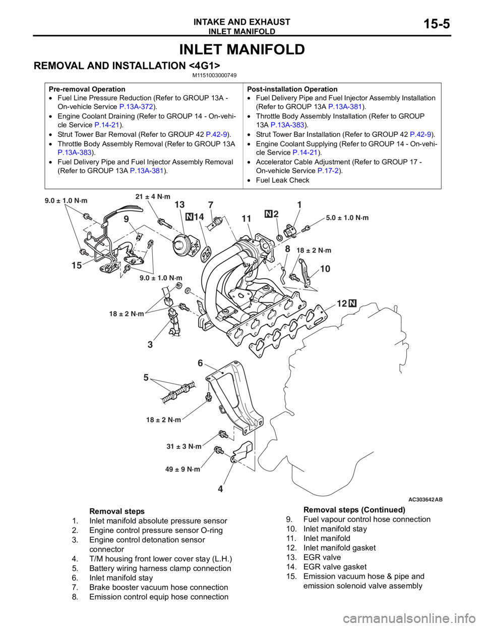
Removal steps
1.Inlet manifold absolute pressure sensor
2.Engine control pressure sensor O-ring
3.Engine control detonation sensor
connector
4.T/M housing front lower cover stay (L.H.)
5.Battery wiring harness clamp connection
6.Inlet manifold stay
7.Brake booster vacuum hose connection
8.Emission control equip hose connection
9.Fuel vapour control hose connection
10.Inlet manifold stay
11 .Inlet manifold
12.Inlet manifold gasket
13.EGR valve
14.EGR valve gasket
15.Emission vacuum hose & pipe and
emission solenoid valve assembly
Removal steps (Continued)
Page 57 of 800
EXHAUST MANIFOLD
INTAKE AND EXHAUST15-7
INSPECTION
M1151003100616
Check the following points; replace the part if a prob-
lem is found.
Inlet Manifold Check
1. Check for damage or cracking of any part.
2. Clogging of the negative pressure (vacuum) outlet port, or clogging of the exhaust gas recirculation
passages.
3. Using a straight edge and feeler gauge, check for distortion of the cylinder head installation surface.
Standard value: 0.15 mm or less
Limit: 0.20 mm
EXHAUST MANIFOLD
REMOVAL AND INSTALLATION <4G1>
M1151003300568
AC30366250 ± 10 N·m
24 ± 4 N·m
35 ± 6 N·m 17 ± 2 N·m
30 ± 2 N·m
N
3
7 12
4
N
6
8
44 ± 5 N·m
AB
9
5N
30 ± 2 N·m
30 ± 2 N·m
30 ± 2 N·m
(Engine oil)
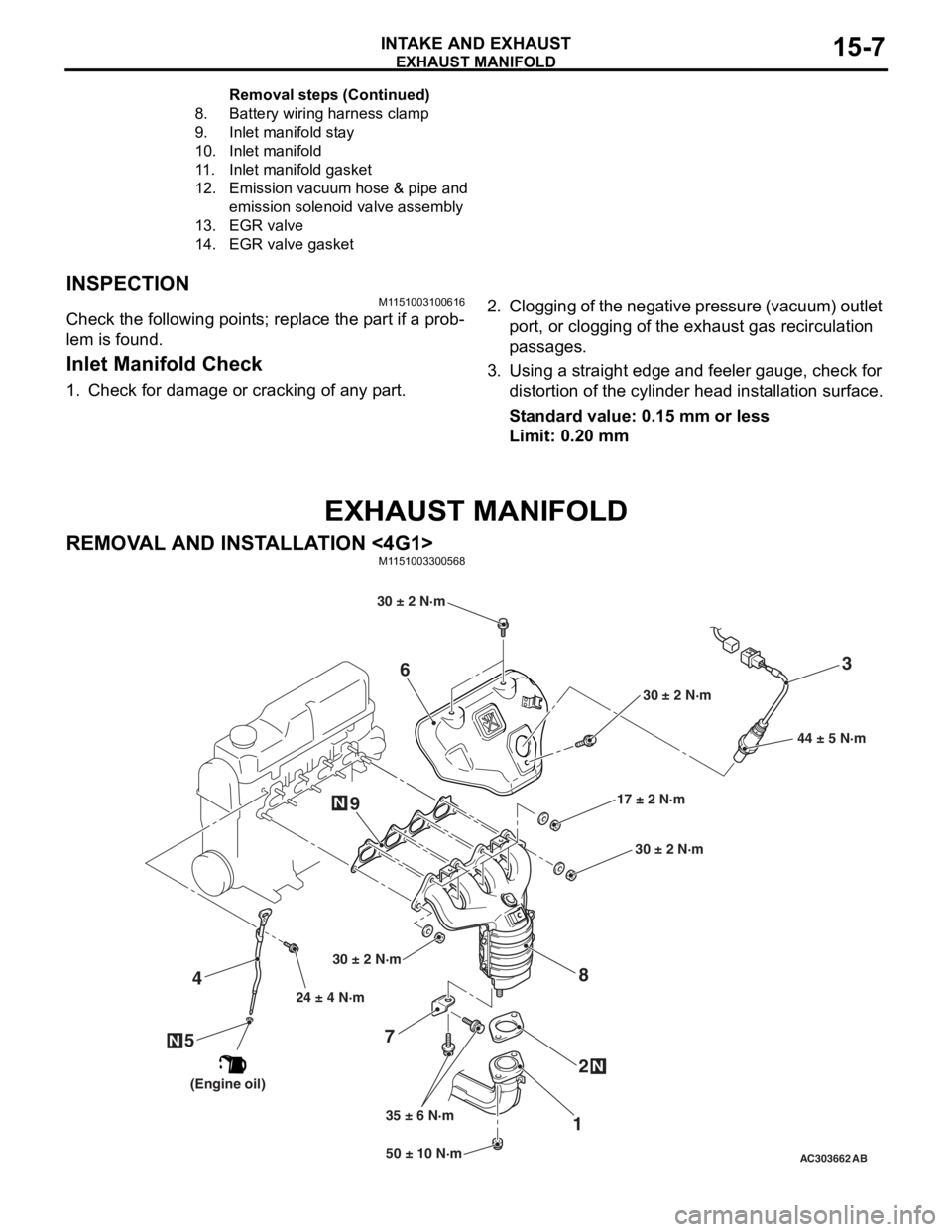
8.Battery wirin g ha rne s s clamp
9.Inlet manifold st ay
10.Inlet manifold
11.Inlet manifold gask et
12.Emission vacuu m hose & pipe and
emis
sion s o lenoid valve assembly
13.EGR v a lve
14.EGR v a lve gasket
Remo va l st ep s ( C o n t in u e d)
Page 58 of 800
Removal steps
1.Front exhaust pipe connection
2.Exhaust pipe gasket
<>>>A<<3.Engine control oxygen sensor (front)
4.Engine oil level gauge and guide
assembly
5.Engine oil filler O-ring
6.Exhaust manifold cover
7.Exhaust manifold bracket
8.Exhaust manifold
9.Exhaust manifold gasket
EXHAUST MANIFOLD
INTAKE AND EXHAUST15-8
REMOVAL SERVICE POINT
<> ENGINE CONTROL OXYGEN SEN-
SOR (FRONT) REMOVAL
AC212566AC
MD998770
Engine control
oxygen sensor
(front)
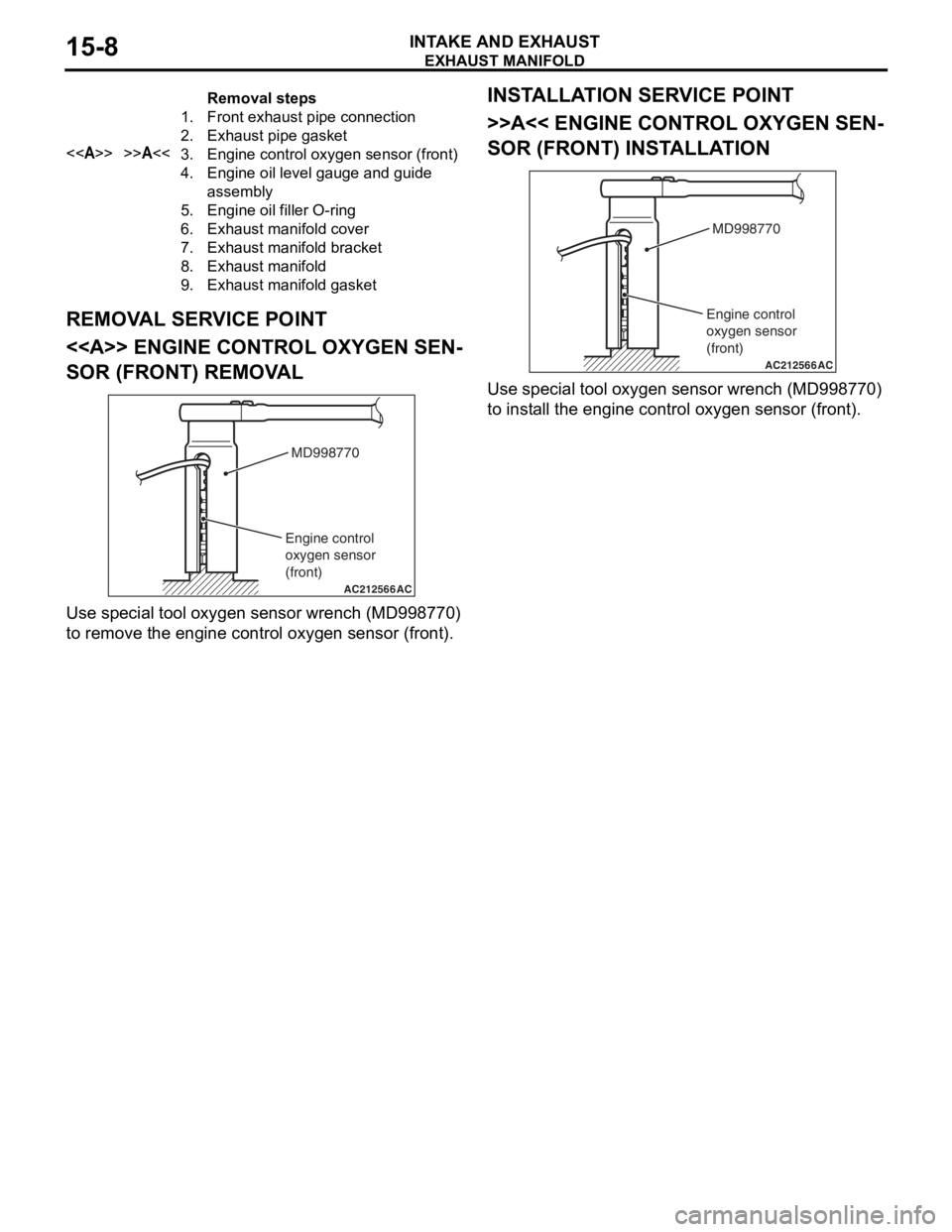
Use spe c ia l tool oxyg en sen s or wrench (MD9987 70)
to remove t
he eng ine contro l oxygen sen s or (fro nt).
INSTALLA T ION SER VICE POINT
>>A<< ENGINE CONT ROL OXYGEN SEN-
SOR (FRONT) INSTALLA TION
AC212566AC
MD998770
Engine control
oxygen sensor
(front)
Use spe c ia l tool oxyg en sen s or wrench (MD9987 70)
to inst
all the eng ine contro l oxyge n sen s or (f ront).