instrument panel MITSUBISHI LANCER 2006 Workshop Manual
[x] Cancel search | Manufacturer: MITSUBISHI, Model Year: 2006, Model line: LANCER, Model: MITSUBISHI LANCER 2006Pages: 800, PDF Size: 45.03 MB
Page 250 of 800
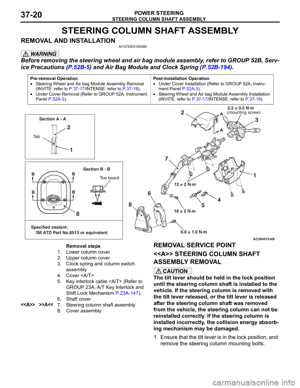
STEERING COLUMN SHAFT ASSEMBLY
POWER STEERING37-20
STEERING COLUMN SHAFT ASSEMBLY
REMOVAL AND INSTALLATIONM1372003100080
WARNING
Before removing the steering wheel and air bag module assembly, refer to GROUP 52B, Serv-
ice Precautions (P.52B-5) and Air Bag Module and Clock Spring (P.52B-194).
Pre-removal Operation
•Steering Wheel and Air bag Module Assembly Removal
(INVITE: refer to
P.37-17/INTENSE: refer to P.37-18).
•Under Cover Removal (Refer to GROUP 52A, Instrument
Panel
P.52A-3).
Post-installation Operation
•Under Cover Installation (Refer to GROUP 52A, Instru-
ment Panel P.52A-3).
•Steering Wheel and Air bag Module Assembly Installation
(INVITE: refer to
P.37-17/INTENSE: refer to P.37-18).
AC304919AB
12 ± 2 N·m
18 ± 2 N·m 5.0 ± 1.0 N·m
1
2
73
2
1
8
8 6
A
A
Ta b Section A - A
Section B - B
BB
Toe board
Specified sealant:
3M ATD Part No.8513 or equivalent
BB
4
5
(mounting screw)2.5 ± 0.5 N·m
Removal steps
1.Lower column cover
2.Upper column cover
3.Clock spring and column switch
assembly
4.Cover
5.Key interlock cable (Refer to
GROUP 23A, A/T Key Interlock and
Shift Lock Mechanism
P.23A-147).
6.Shaft cover
<>>>A<<7.Steering column shaft assembly
8.Cover assembly
REMOVAL SERVICE POINT
<> STEERING
COLUMN SHAFT
ASSEMBLY REMOVAL
CAUTION
The tilt lever should be held in the lock position
until the steering column shaft is installed to the
vehicle. If the steering column is removed with
the tilt lever released, or the tilt lever is released
after the steering column shaft was removed
from the vehicle, the steering column can not be
reinstalled correctly. If the steering column is
installed incorrectly, the collision energy absorb
-
ing mechanism may be damaged.
1. Ensure that the tilt lever is in the lock position, and remove the steering column mounting bolts.
Page 382 of 800
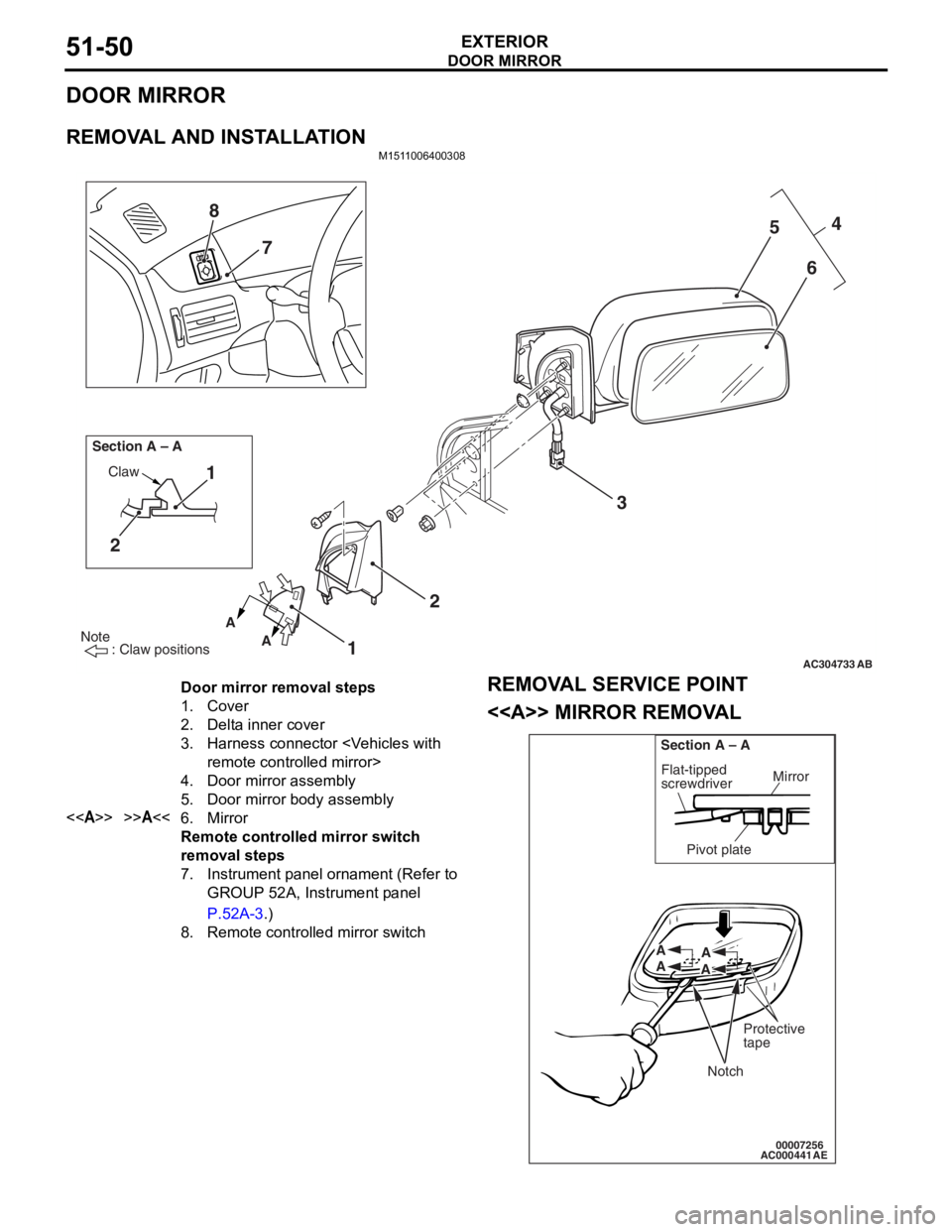
DOOR MIRROR
EXTERIOR51-50
DOOR MIRROR
REMOVAL AND INSTALLATION
M1511006400308
AC304733
Note
: Claw positions
AB
AA
Section A – A
Claw1
2
12 3 4
5
6
7
8
Door mirror removal steps
1.Cover
2.Delta inner cover
3.Harness connector
4.Door mirror assembly
5.Door mirror body assembly
<>>>A<<6.Mirror
Remote controlled mirror switch
removal steps
7.Instrument panel ornament (Refer to
GROUP 52A, Instrument panel
P.52A-3.)
8.Remote controlled mirror switch
REMOV
A L SER VICE POINT
<> MIRROR REMOV A L
AC00044100007256
Mirror
Flat-tipped
screwdriver
Section A – A
Pivot plate
Notch
Protective
tape
A
A A
A
AE
Page 412 of 800

OVERALL CONFIGURATION DIAGRAM
CONFIGURATION DIAGRAMS80-2
OVERALL CONFIGURATION DIAGRAM
OVERALL WIRING DIAGRAM
AC301175AB
Front wiring
harness (RH) Control wiring
harness Instrument panel
wiring harness Roof wiring
harnessFloor wiring
harness (RH)
Battery wiring
harness Front wiring
harness (LH) Front door
wiring harness
Floor wiring
harness (LH) Fuel wiring
harnessRear door
wiring harness
Front bumper
wiring harness
Rear bumper
wiring harness
*
*
NO
TE: .
1.This illu stration shows o n ly major wirin g harne sses.
2.*: also eq uipp ed at t he rig h t side.
Page 413 of 800
OVERALL CONFIGURATION DIAGRAM
CONFIGURATION DIAGRAMS80-3
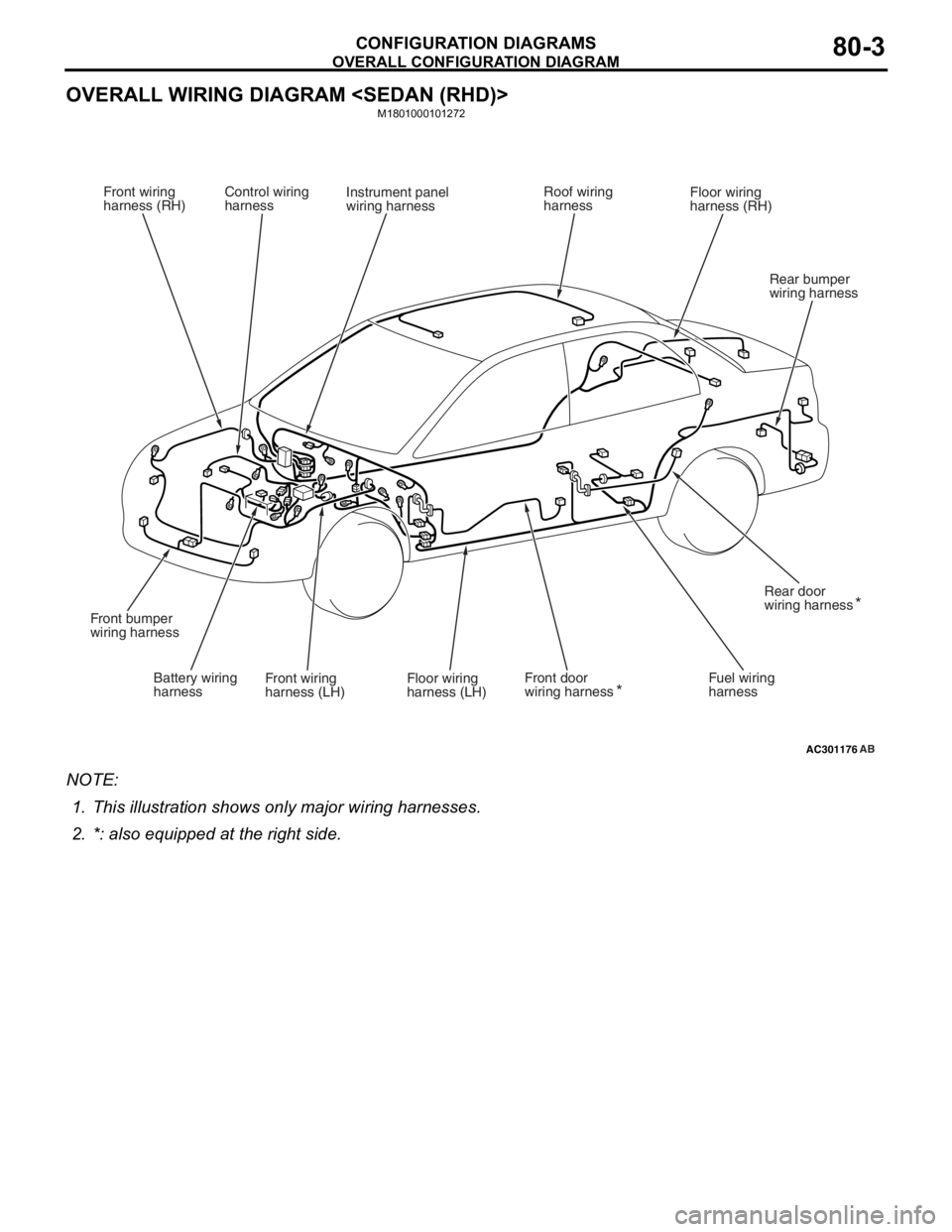
OVERALL WIRING DIAGRAM
M1801000101272
AC301176AB
Front wiring
harness (RH) Control wiring
harness Instrument panel
wiring harness Roof wiring
harnessFloor wiring
harness (RH)
Battery wiring
harness Front wiring
harness (LH) Front door
wiring harness
Floor wiring
harness (LH) Fuel wiring
harnessRear door
wiring harness
Front bumper
wiring harness
Rear bumper
wiring harness
*
*
NO
TE: .
1.This illu stration shows o n ly major wirin g harne sses.
2.*: also eq uipp ed at t he rig h t side.
Page 414 of 800
OVERALL CONFIGURATION DIAGRAM
CONFIGURATION DIAGRAMS80-4
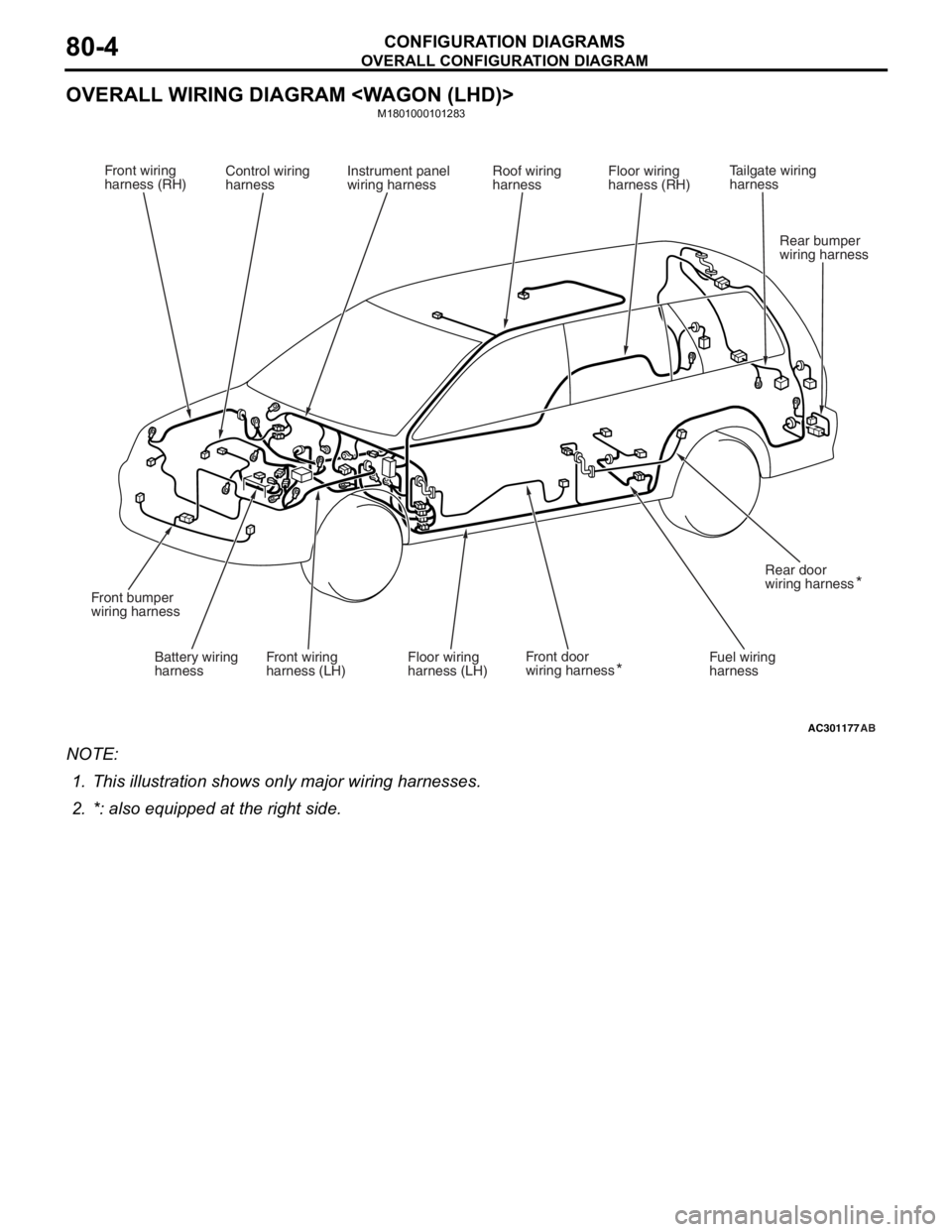
OVERALL WIRING DIAGRAM
M1801000101283
AC301177AB
Front wiring
harness (RH)Control wiring
harness Instrument panel
wiring harness Roof wiring
harnessFloor wiring
harness (RH)
Battery wiring
harness Front wiring
harness (LH) Front door
wiring harness
Floor wiring
harness (LH) Fuel wiring
harnessRear door
wiring harness
Front bumper
wiring harness
Rear bumper
wiring harness
*
*
Tailgate wiring
harness
NO
TE: .
1.This illu stration shows o n ly major wirin g harne sses.
2.*: also eq uipp ed at t he rig h t side.
Page 415 of 800
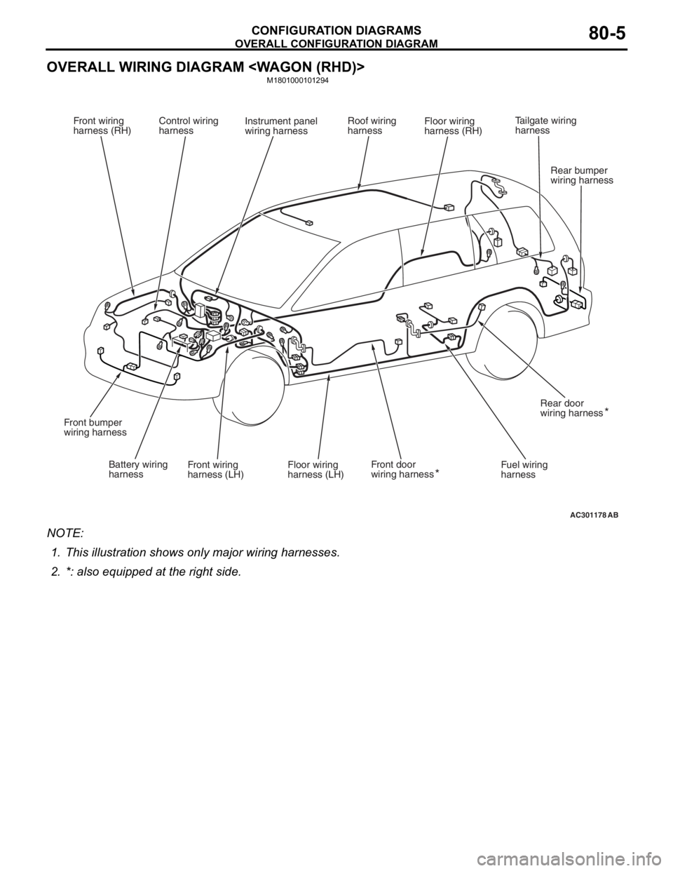
OVERALL CONFIGURATION DIAGRAM
CONFIGURATION DIAGRAMS80-5
OVERALL WIRING DIAGRAM
M1801000101294
AC301178AB
Front wiring
harness (RH)Control wiring
harness Instrument panel
wiring harness Roof wiring
harnessFloor wiring
harness (RH)
Battery wiring
harness Front wiring
harness (LH) Front door
wiring harness
Floor wiring
harness (LH) Fuel wiring
harnessRear door
wiring harness
Front bumper
wiring harness
Rear bumper
wiring harness
*
*
Tailgate wiring
harness
NO
TE: .
1.This illu stration shows o n ly major wirin g harne sses.
2.*: also eq uipp ed at t he rig h t side.
Page 436 of 800
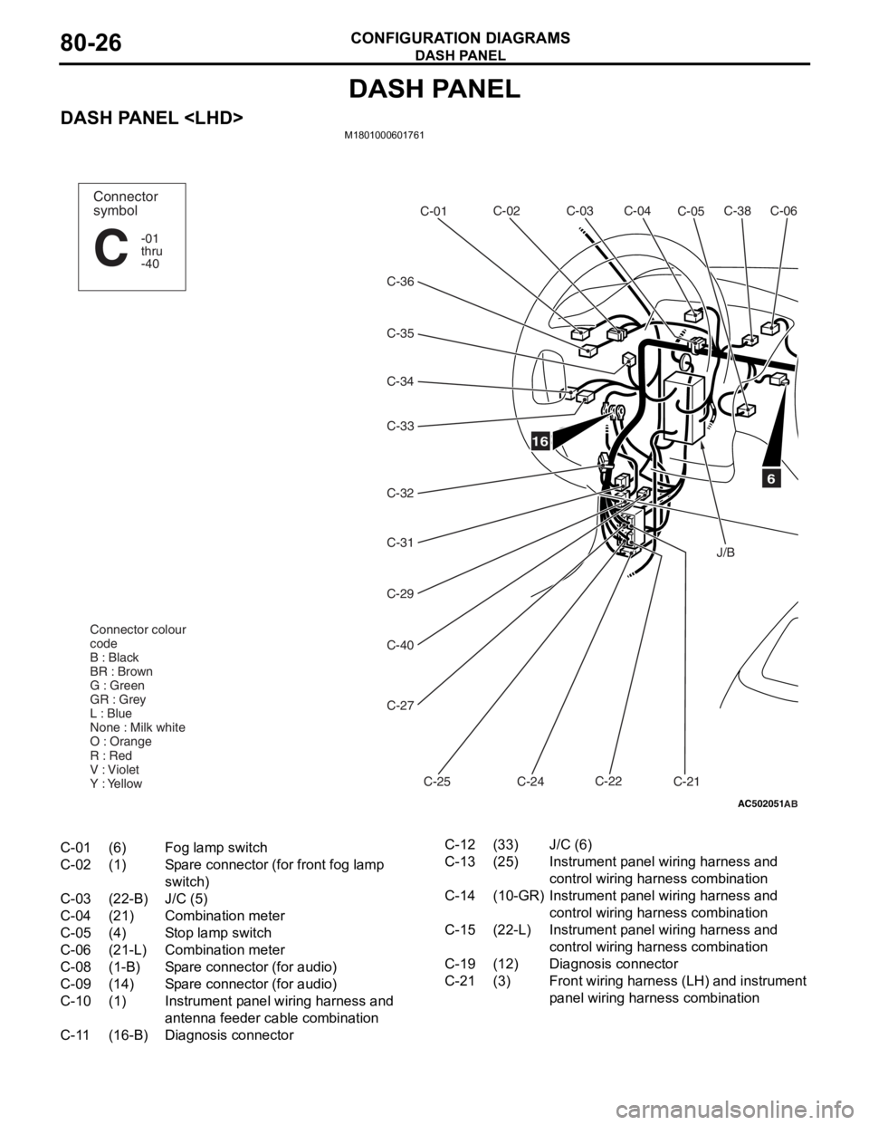
DASH PANEL
CONFIGURATION DIAGRAMS80-26
DASH PANEL
DASH PANEL
AC502051
16
C-38C-06
C-05
C-02
C-01
C-34
C-32 C-31
C-29
C-40
C-27
C-25 C-24C-22
C-21
Connector colour
code
B : Black
BR : Brown
G : Green
GR : Grey
L : Blue
None : Milk white
O : Orange
R : Red
V : Violet
Y : Yellow
Connector
symbol
-01
thru
-40
C
C-04
C-03
C-36
C-33
C-35
6
J/B
AB
C-01(6)Fog lamp switch
C-02(1)Spare connector (for front fog lamp
switch)
C-03(22-B)J/C (5)
C-04(21)Combination meter
C-05(4)Stop lamp switch
C-06(21-L)Combination meter
C-08(1-B)Spare connector (for audio)
C-09(14)Spare connector (for audio)
C-10(1)Instrument panel wiring harness and
antenna feeder cable combination
C-11(16-B)Diagnosis connector
C-12(33)J/C (6)
C-13(25)Instrument panel wiring harness and
control wiring harness combination
C-14(10-GR)Instrument panel wiring harness and
control wiring harness combination
C-15(22-L)Instrument panel wiring harness and
control wiring harness combination
C-19(12)Diagnosis connector
C-21(3)Front wiring harness (LH) and instrument
panel wiring har ness combination
Page 437 of 800
AC502052AB
5
14
15
C-08C-39C-09
C-11C-12
C-10
C-14
C-15
C-13
Instrument panel
wiring harness
Control wiring
harness
C-19
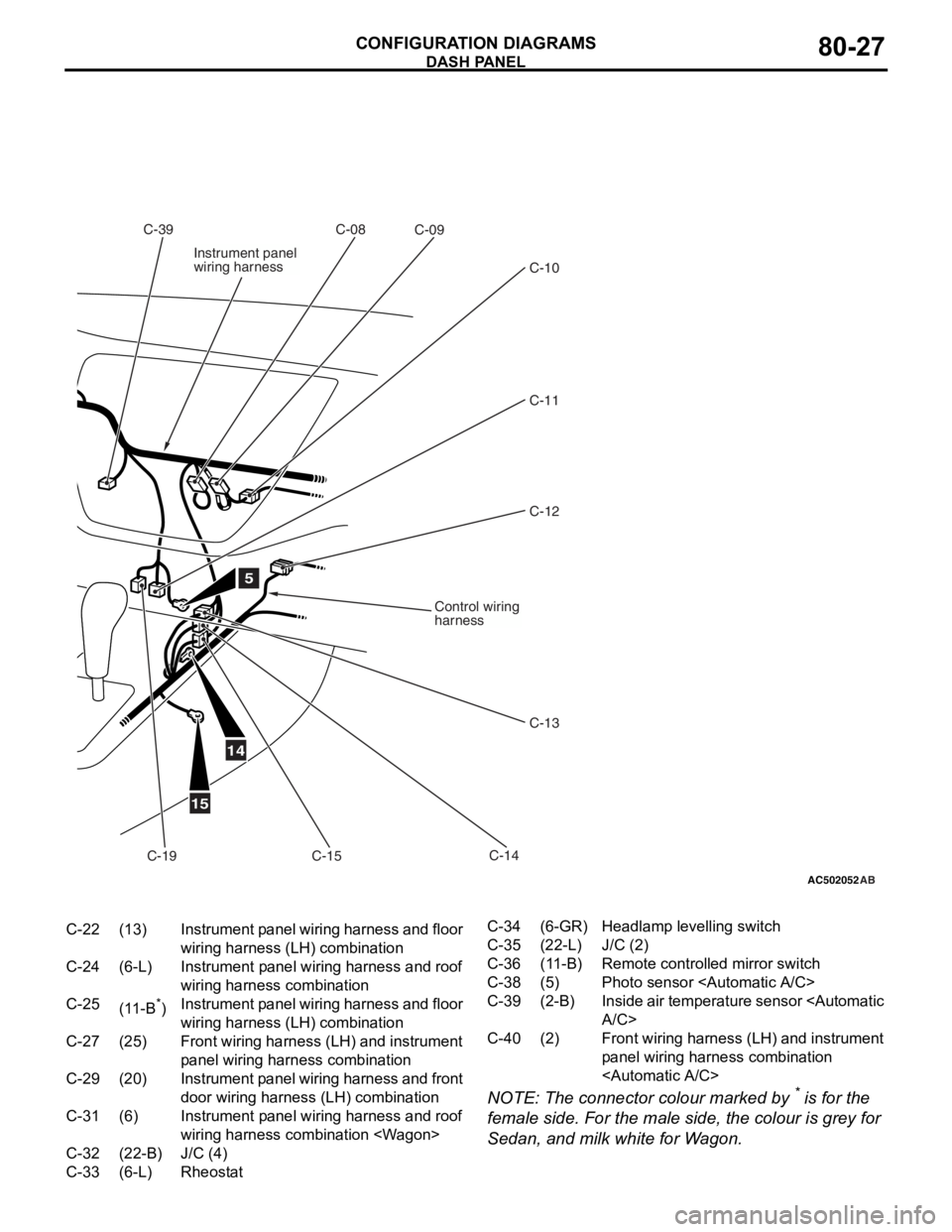
C-22(13)Instrument panel wiring harness and floor
wiring harness (LH) combination
C-24(6-L)Instrument panel wiring harness and roof
wiring harness combination
C-25(11-B*)Instrument panel wiring harness and floor
wiring harness (LH) combination
C-27(25)Front wiring harness (LH) and instrument
panel wiring harn ess combination
C-29(20)Instrument panel wiring harness and front
door wiring harness (LH) combination
C-31(6)Instrument panel wiring harness and roof
wiring harness combination
C-32(22-B)J/C (4)
C-33(6-L)Rheostat
C-34(6-GR)Headlamp levelling switch
C-35(22-L)J/C (2)
C-36(11-B)Remote controlled mirror switch
C-38(5)Photo sensor
C-39(2-B)Inside air temperature sensor
C-40(2)Front wiring harness (LH) and instrument
panel wiring harness combination
DASH P ANEL
CONF IGURA TION D I A G RA MS80-27
NOTE: The conn ecto r colour marked by * is fo r the
female side. F
o
r the male
side, the
colour is grey for
Se
dan, a
nd milk white f
o
r W
a
g
on.
Page 438 of 800
DASH PANEL
CONFIGURATION DIAGRAMS80-28
DASH PANEL
AC502053
C-140C-102
C-103
C-141
C-101
C-132
C-139
C-148
C-130
C-146C-145
Y
4
Connector
symbol
-101
thru
-149
C
Connector colour
code
B : Black
BR : Brown
G : Green
GR : Grey
L : Blue
None : Milk white
O : Orange
R : Red
V : Violet
Y : Yellow
Instrument panel
wiring harness
C-131
C-133
C-147
AB
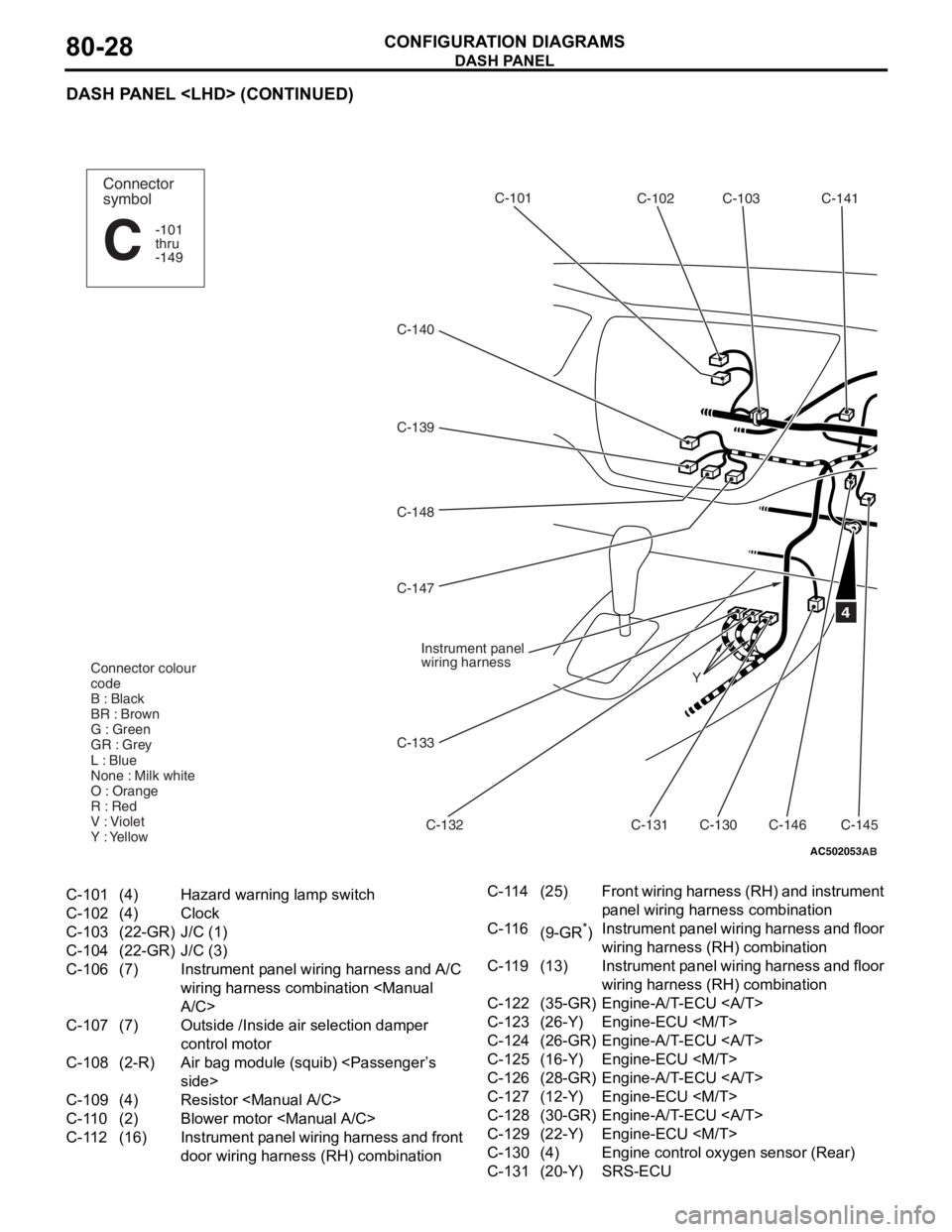
C-101(4)Hazard warning lamp switch
C-102(4)Clock
C-103(22-GR)J/C (1)
C-104(22-GR)J/C (3)
C-106(7)Instrument panel wiring harness and A/C
wiring harness combination
C-107(7)Outside /Inside air selection damper
control motor
C-108(2-R)Air bag module (squib)
C-109(4)Resistor
C-110(2)Blower motor
C-112(16)Instrument panel wiring harness and front
door wiring harness (RH) combination
C-114(25)Front wiring harness (RH) and instrument
panel wiring har
ness combination
C-116(9-GR*)Instrument panel wiring harness and floor
wiring harness (RH) combination
C-119(13)Instrument panel wiring harness and floor
wiring harness (RH) combination
C-122(35-GR)Engine-A/T-ECU
C-123(26-Y)Engine-ECU
C-124(26-GR)Engine-A/T-ECU
C-125(16-Y)Engine-ECU
C-126(28-GR)Engine-A/T-ECU
C-127(12-Y)Engine-ECU
C-128(30-GR)Engine-A/T-ECU
C-129(22-Y)Engine-ECU
C-130(4)Engine control oxygen sensor (Rear)
C-131(20-Y)SRS-ECU
Page 439 of 800
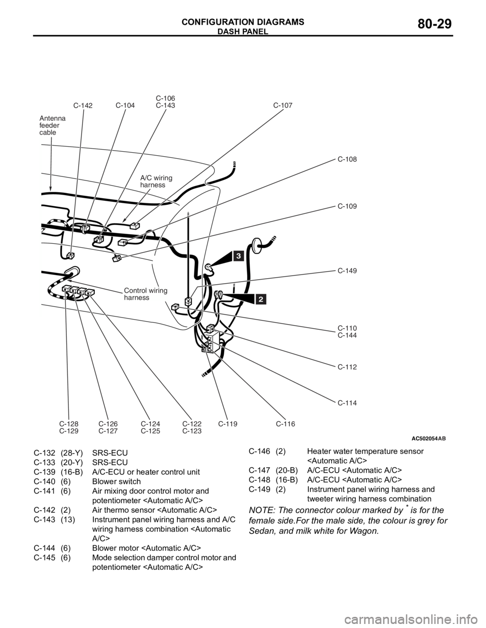
AC502054
C-142
AB
C-104C-106
C-143
C-107
C-109
C-149
C-110
C-144
C-112
C-114
C-116
C-119
C-126
C-127
C-128
C-129
2
C-108
C-124
C-125C-122
C-123
3
Control wiring
harness
A/C wiring
harness
Antenna
feeder
cable
C-132(28-Y)SRS-ECU
C-133(20-Y)SRS-ECU
C-139(16-B)A/C-ECU or heater control unit
C-140(6)Blower switch
C-141(6)Air mixing door control motor and
potentiometer
C-142(2)Air thermo sensor
C-143(13)Instrument panel wiring harness and A/C
wiring harness combination
C-144(6)Blower motor
C-145(6)Mode selection damper control motor and
potentiometer
C-146(2)Heater water temperature sensor
C-147(20-B)A/C-ECU
C-148(16-B)A/C-ECU
C-149(2)Instrument panel wiring harness and
tweeter wiring harn
ess combination
DASH P ANEL
CONF IGURA TION D I A G RA MS80-29
NOTE: The conn ecto r colour marked by * is fo r the
female side.F
o
r the male
sid
e
, the
colour is grey for
Se
dan, a
nd milk white f
o
r W
a
g
on.