power steering pressure sensor switch MITSUBISHI LANCER 2006 Workshop Manual
[x] Cancel search | Manufacturer: MITSUBISHI, Model Year: 2006, Model line: LANCER, Model: MITSUBISHI LANCER 2006Pages: 800, PDF Size: 45.03 MB
Page 104 of 800
IGNITION SYSTEM
ENGINE ELECTRICAL16-42
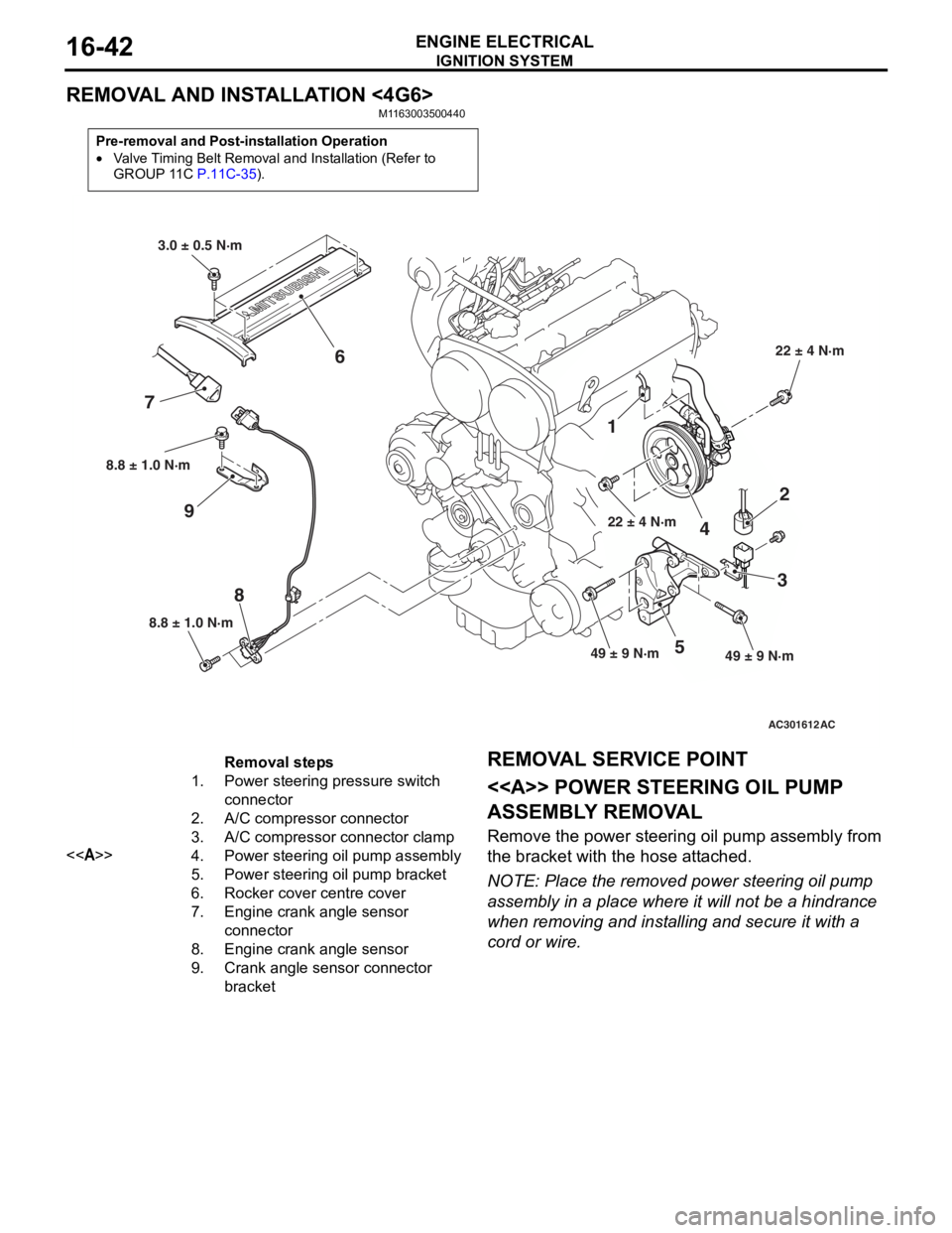
REMOVAL AND INSTALLATION <4G6>
M1163003500440
Pre-removal and Post-installation Operation
•Valve Timing Belt Removal and Installation (Refer to
GROUP 11C P.11C-35).
AC301612
8.8 ± 1.0 N·m
8
8.8 ± 1.0 N·m
9
1
22 ± 4 N·m
4
2
3
49 ± 9 N·m49 ± 9 N·m5
22 ± 4 N·m
3.0 ± 0.5 N·m
6
7
AC
Removal steps
1.Power steering pressure switch
connector
2.A/C compressor connector
3.A/C compressor connector clamp
<>4.Power steering oil pump assembly
5.Power steering oil pump bracket
6.Rocker cover centre cover
7.Engine crank angle sensor
connector
8.Engine crank angle sensor
9.Crank angle sensor connector
bracket
REMOV A L SER VICE POINT
<> POWE R STEERING OIL PUMP
ASSEMBL
Y REMOV A L
Remove the p o wer st eering oil pump assembly from
the bra
cke t with th e hose att a ched.
NOTE: Place the remo ved power st eering oil pump
assembly in a place where it will not be a hindrance
wh
en removing an d inst a lling an d secure it with a
cord or wire.
Page 231 of 800
37-1
GROUP 37
POWER STEERING
CONTENTS
GENERAL INFORMATION . . . . . . . .37-3
SERVICE SPECIFICATIONS . . . . . . .37-6
LUBRICANTS . . . . . . . . . . . . . . . . . .37-7
SEALANTS . . . . . . . . . . . . . . . . . . . .37-7
SPECIAL TOOLS . . . . . . . . . . . . . . . .37-8
ON-VEHICLE SERVICE . . . . . . . . . . .37-11
STEERING WHEEL FREE PLAY CHECK . 37-11
STEERING ANGLE CHECK . . . . . . . . . . . . 37-11
TIE ROD END BALL JOINT TURNING
TORQUE CHECK . . . . . . . . . . . . . . . . . . . . 37-12
STATIONARY STEERING EFFORT
CHECK . . . . . . . . . . . . . . . . . . . . . . . . . . . . 37-12
STEERING WHEEL RETURN TO
CENTRE CHECK . . . . . . . . . . . . . . . . . . . . 37-13
DRIVE BELT TENSION CHECK. . . . . . . . . 37-13
FLUID LEVEL CHECK . . . . . . . . . . . . . . . . 37-13
FLUID REPLACEMENT . . . . . . . . . . . . . . . 37-13
POWER STEERING SYSTEM AIR
BLEEDING . . . . . . . . . . . . . . . . . . . . . . . . . 37-14
OIL PUMP PRESSURE TEST . . . . . . . . . . 37-14
POWER STEERING PRESSURE
SWITCH CHECK . . . . . . . . . . . . . . . . . . . . . 37-15
TIE ROD END BALL JOINT DUST
COVER CHECK . . . . . . . . . . . . . . . . . . . . . 37-15
STEERING COLUMN SHAFT ASSEMBLY
SHOCK ABSORBING MECHANISM
CHECK . . . . . . . . . . . . . . . . . . . . . . . . . . . . 37-15
STEERING WHEEL . . . . . . . . . . . . . .37-17
REMOVAL AND INSTALLATION
REMOVAL AND INSTALLATION
Continued on next page
WARNINGS REGARDING SERVICING OF SUPPLEMENTAL RESTRAINT SYSTEM (SRS) EQUIPPED VEHICLES
WARNING
•Improper service or maintenance of any component of the SRS, or any SRS-related component, can lead to
personal injury or death to service personnel (from inad vertent firing of the air bag) or to the driver and
paassenger (from renderin g the SRS inoperative).
•Service or maintenance of any SRS component or SRS-related component must be performed only at an
authorized MITSUBISHI dealer.
•MITSUBISHI dealer personnel must thoroughly review th is manual, and especially its GROUP 52B - Supplemental
Restraint System (SRS) before begi nning any service or maintenance of any component of the SRS or any
SRS-related component.
NOTE
The SRS includes the following components: SRS air bag control unit, SRS warning light, front impact sensors, air bag module,
clock spring, and interconnecting wiring. Other SRS-related components (that may have to be removed/installed in connection
with SRS service or maintenance) are indicated in the table of contents by an asterisk (*).
Page 423 of 800
AC301130AC
9
10
11
13
B-103B-104 B-105
B-107
B-108
Battery wiring
harness
B-109
B-110
B-111
*
B-112
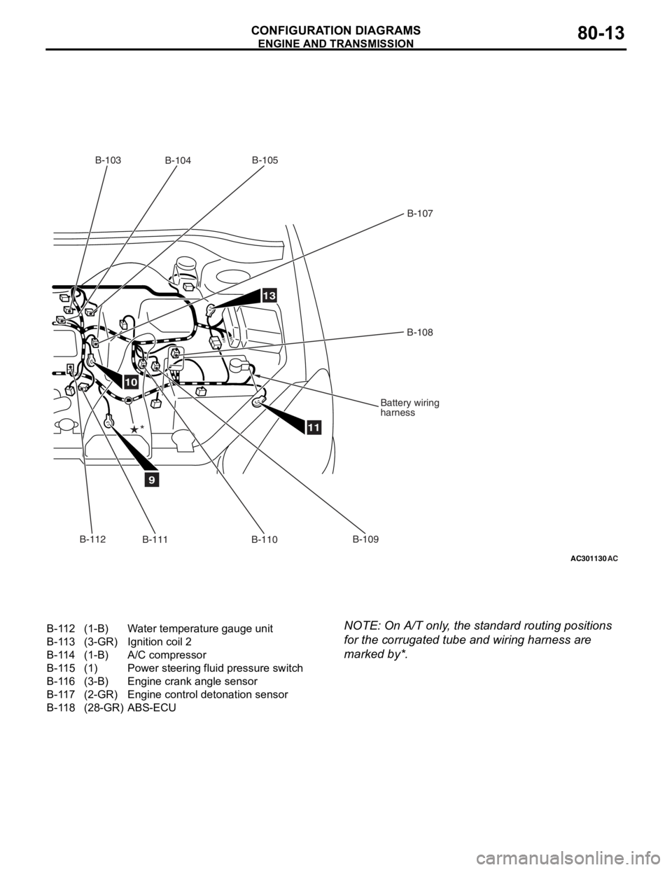
B-112(1-B)Water temperature gauge unit
B-113(3-GR)Ignition coil 2
B-114(1-B)A/C compressor
B-115(1)Power steering fluid pressure switch
B-116(3-B)Engine crank angle sensor
B-117(2-GR)Engine control detonation sensor
B-118(28-GR)ABS-ECU
ENGINE AND TRA
N SMISSION
CONF IGURA TION D I A G RA MS80-13
NOTE: On A/T only , the st andard routing positions
for the
corrug a ted tu be and wiring harne ss are
marked by*.
Page 427 of 800
AC301133AC
9
10
11
13
B-103B-104 B-105
B-107
B-108
Battery wiring
harness
B-109
B-110
B-111
*
B-112
B-118
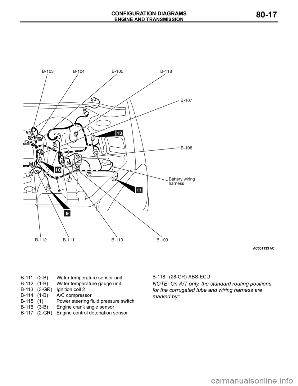
B-111(2-B)Water temperature sensor unit
B-112(1-B)Water temperature gauge unit
B-113(3-GR)Ignition coil 2
B-114(1-B)A/C compressor
B-115(1)Power steering fluid pressure switch
B-116(3-B)Engine crank angle sensor
B-117(2-GR)Engine control detonation sensor
B-118(28-GR)ABS-ECU
ENGINE AND TRA
N SMISSION
CONF IGURA TION D I A G RA MS80-17
NOTE: On A/T only , the st andard routing positions
for the
corrug a ted tu be and wiring harne ss are
marked by*.
Page 431 of 800
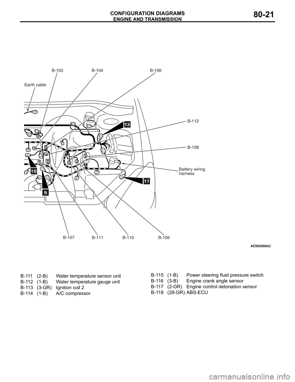
AC502050AC
9
10
11
13
B-103B-104
B-106
B-112B-108
Battery wiring
harness
B-111
B-110B-107
Earth cable
B-109
B-111(2-B)Water temperature sensor unit
B-112(1-B)Water temperature gauge unit
B-113(3-GR)Ignition coil 2
B-114(1-B)A/C compressor
B-115(1-B)Power steering fluid pressure switch
B-116(3-B)Engine crank angle sensor
B-117(2-GR)Engine control detonation sensor
B-118(28-GR)ABS-ECU
ENGINE AND TRA N SMISSION
CONF IGURA TION D I A G RA MS80-21
Page 435 of 800
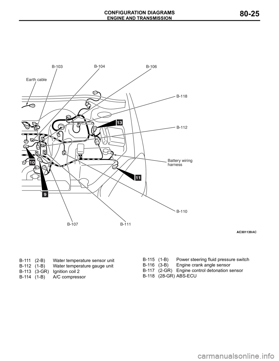
AC301139AC
9
11
13
B-103B-106
B-118
B-112
Battery wiring
harness
B-110
B-111
B-107
B-104
10
Earth cable
B-111(2-B)Water temperature sensor unit
B-112(1-B)Water temperature gauge unit
B-113(3-GR)Ignition coil 2
B-114(1-B)A/C compressor
B-115(1-B)Power steering fluid pressure switch
B-116(3-B)Engine crank angle sensor
B-117(2-GR)Engine control detonation sensor
B-118(28-GR)ABS-ECU
ENGINE AND TRA N SMISSION
CONF IGURA TION D I A G RA MS80-25
Page 517 of 800
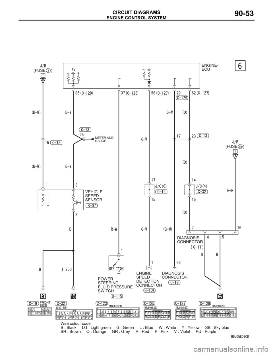
ENGINE CONTROL SYSTEM
CIRCUIT DIAGRAMS90-53
ENGINE-
ECU
(FUSE )
2
(FUSE )15
DIAGNOSIS
CONNECTOR
DIAGNOSIS
CONNECTOR
POWER
STEERING
FLUID PRESSURE
SWITCHENGINE
SPEED
DETECTION
CONNECTOR VEHICLE
SPEED
SENSOR
METER AND
GAUGE
FRONT
SIDE
Wire colour code
B : Black LG : Light green G : Green L : Blue W : White Y : Yellow SB : Sky blue
BR : Brown O : Orange GR : Grey R : Red P : Pink V : Violet PU : Purple
Page 523 of 800
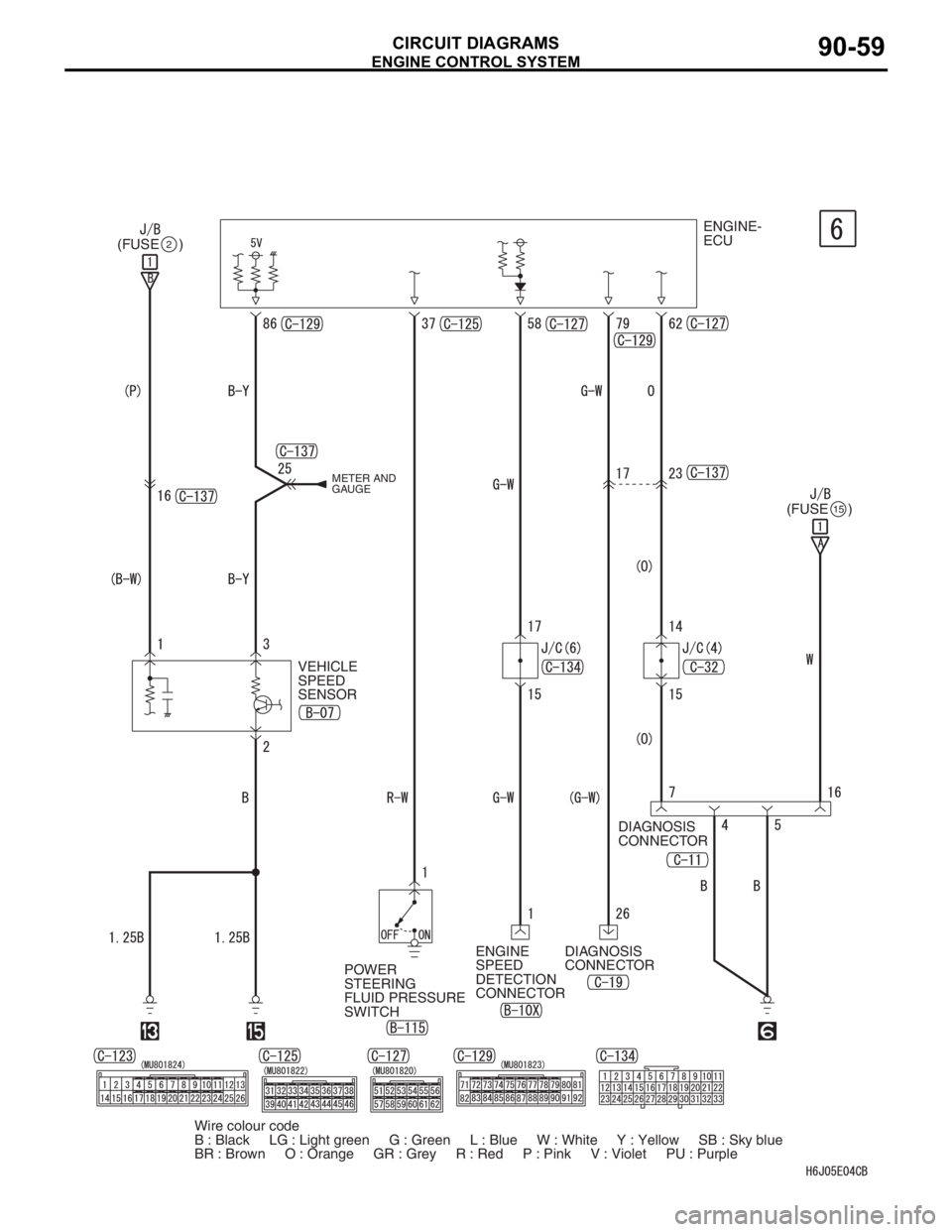
ENGINE CONTROL SYSTEM
CIRCUIT DIAGRAMS90-59
ENGINE-
ECU
(FUSE )
2
(FUSE )15
DIAGNOSIS
CONNECTOR
DIAGNOSIS
CONNECTOR
POWER
STEERING
FLUID PRESSURE
SWITCHENGINE
SPEED
DETECTION
CONNECTOR VEHICLE
SPEED
SENSOR
METER AND
GAUGE
Wire colour code
B : Black LG : Light green G : Green L : Blue W : White Y : Yellow SB : Sky blue
BR : Brown O : Orange GR : Grey R : Red P : Pink V : Violet PU : Purple
Page 529 of 800
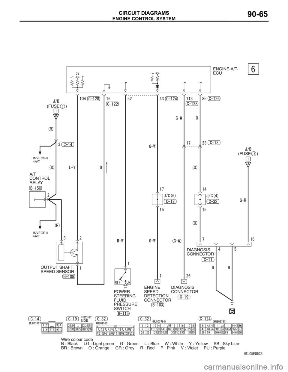
ENGINE CONTROL SYSTEM
CIRCUIT DIAGRAMS90-65
FRONT
SIDE
ENGINE-A/T-
ECU
(FUSE )
3
(FUSE )15
DIAGNOSIS
CONNECTOR
DIAGNOSIS
CONNECTOR ENGINE
SPEED
DETECTION
CONNECTOR OUTPUT SHAFT
SPEED SENSOR A/T
CONTROL
RELAY
INVECS-II
4A/T INVECS-II
4A/T
POWER
STEERING
FLUID
PRESSURE
SWITCH
Wire colour code
B : Black LG : Light green G : Green L : Blue W : White Y : Yellow SB : Sky blue
BR : Brown O : Orange GR : Grey R : Red P : Pink V : Violet PU : Purple
Page 535 of 800
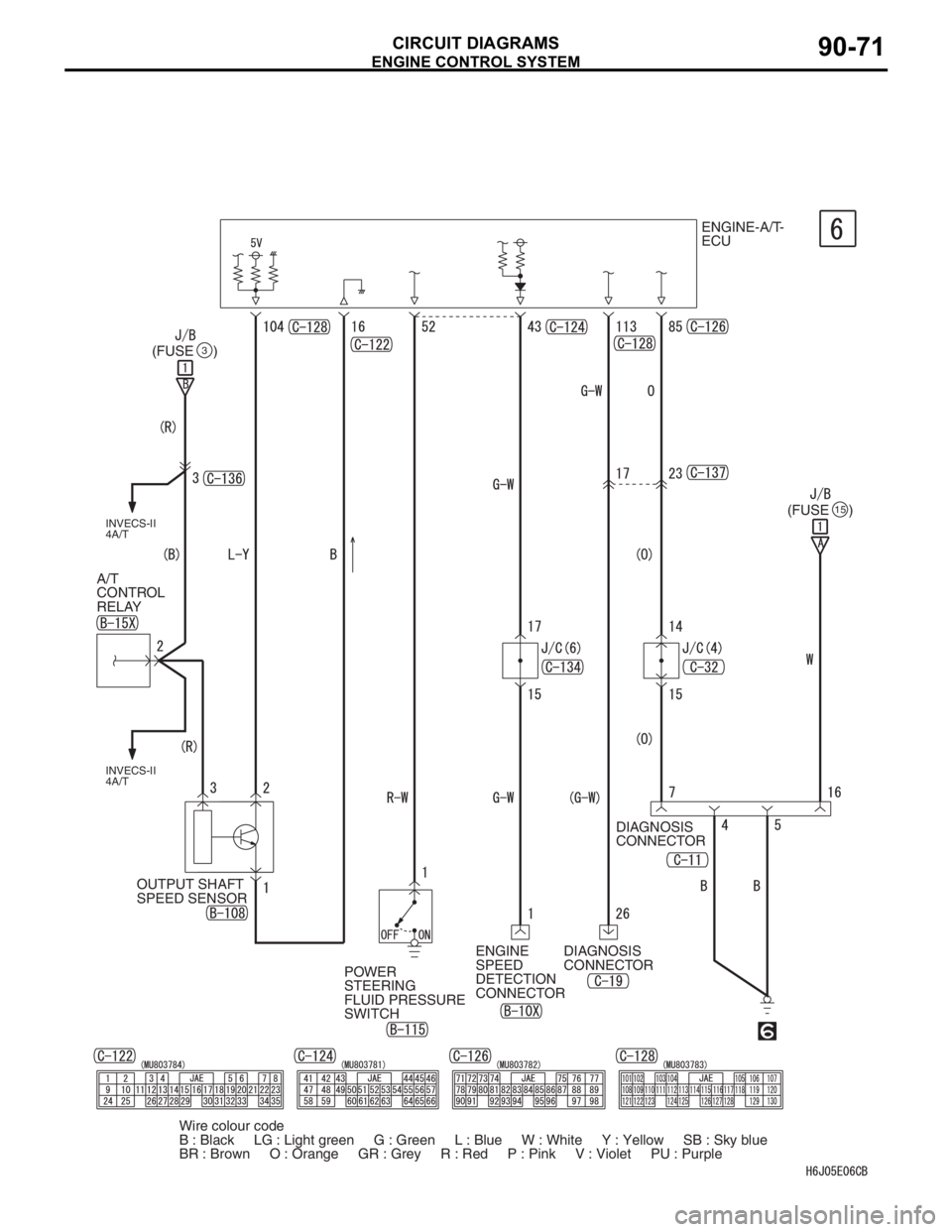
ENGINE CONTROL SYSTEM
CIRCUIT DIAGRAMS90-71
ENGINE-A/T-
ECU
(FUSE )
(FUSE )
DIAGNOSIS
CONNECTOR
DIAGNOSIS
CONNECTOR
POWER
STEERING
FLUID PRESSURE
SWITCHENGINE
SPEED
DETECTION
CONNECTOR OUTPUT SHAFT
SPEED SENSOR A/T
CONTROL
RELAY
INVECS-II
4A/T INVECS-II
4A/T
3
15
Wire colour code
B : Black LG : Light green G : Green L : Blue W : White Y : Yellow SB : Sky blue
BR : Brown O : Orange GR : Grey R : Red P : Pink V : Violet PU : Purple