turn signal MITSUBISHI LANCER 2006 Workshop Manual
[x] Cancel search | Manufacturer: MITSUBISHI, Model Year: 2006, Model line: LANCER, Model: MITSUBISHI LANCER 2006Pages: 800, PDF Size: 45.03 MB
Page 92 of 800
IGNITION SYSTEM
ENGINE ELECTRICAL16-30
IGNITION SYSTEM
GENERAL INFORMATIONM1163000100294
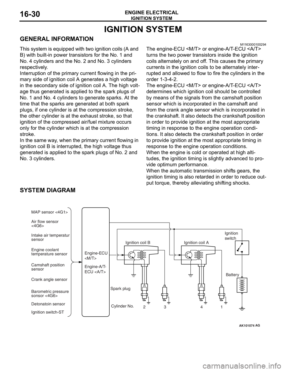
This system is equipped with two ignition coils (A and
B) with built-in power transistors for the No. 1 and
No. 4 cylinders and the No. 2 and No. 3 cylinders
respectively.
Interruption of the primary current flowing in the pri-
mary side of ignition coil A generates a high voltage
in the secondary side of ignition coil A. The high volt
-
age thus generated is applied to the spark plugs of
No. 1 and No. 4 cylinders to generate sparks. At the
time that the sparks are generated at both spark
plugs, if one cylinder is at the compression stroke,
the other cylinder is at the exhaust stroke, so that
ignition of the compressed air/fuel mixture occurs
only for the cylinder which is at the compression
stroke.
In the same way, when the primary current flowing in
ignition coil B is interrupted, the high voltage thus
generated is applied to the spark plugs of No. 2 and
No. 3 cylinders.
The engine-ECU
turns the two power transistors inside the ignition
coils alternately on and off. This causes the primary
currents in the ignition coils to be alternately inter
-
rupted and allowed to flow to fire the cylinders in the
order 1-3-4-2.
The engine-ECU
determines which ignition coil should be controlled
by means of the signals from the camshaft position
sensor which is incorporated in the camshaft and
from the crank angle sensor which is incorporated in
the crankshaft. It also detects the crankshaft position
in order to provide ignition at the most appropriate
timing in response to the engine operation condi
-
tions. It also detects the crankshaft position in order
to provide ignition at the most appropriate timing in
response to the engine operation conditions.
When the engine is cold or operated at high alti-
tudes, the ignition timing is slightly advanced to pro-
vide optimum performance.
When the automatic transmission shifts gears, the
ignition timing is also retarded in order to reduce out
-
put torque, thereby alleviating shifting shocks.
SYSTEM DIAGRAM
AK101074
Air flow sensor
<4G6> MAP sensor <4G1>
Intake air temperatur
sensor
Engine coolant
temperature sensor
Camshaft position
sensor
Crank angle sensor
Barometric pressure
sonsor <4G6>
Detonatoin sensor
Ignition switch-ST Engine-A/T-
ECU Engine-ECU
Ignition coil B
Cylinder No. 23 4
AG
1
Spark plug Ignition coil A
Ignition
switch
Battery
Page 277 of 800
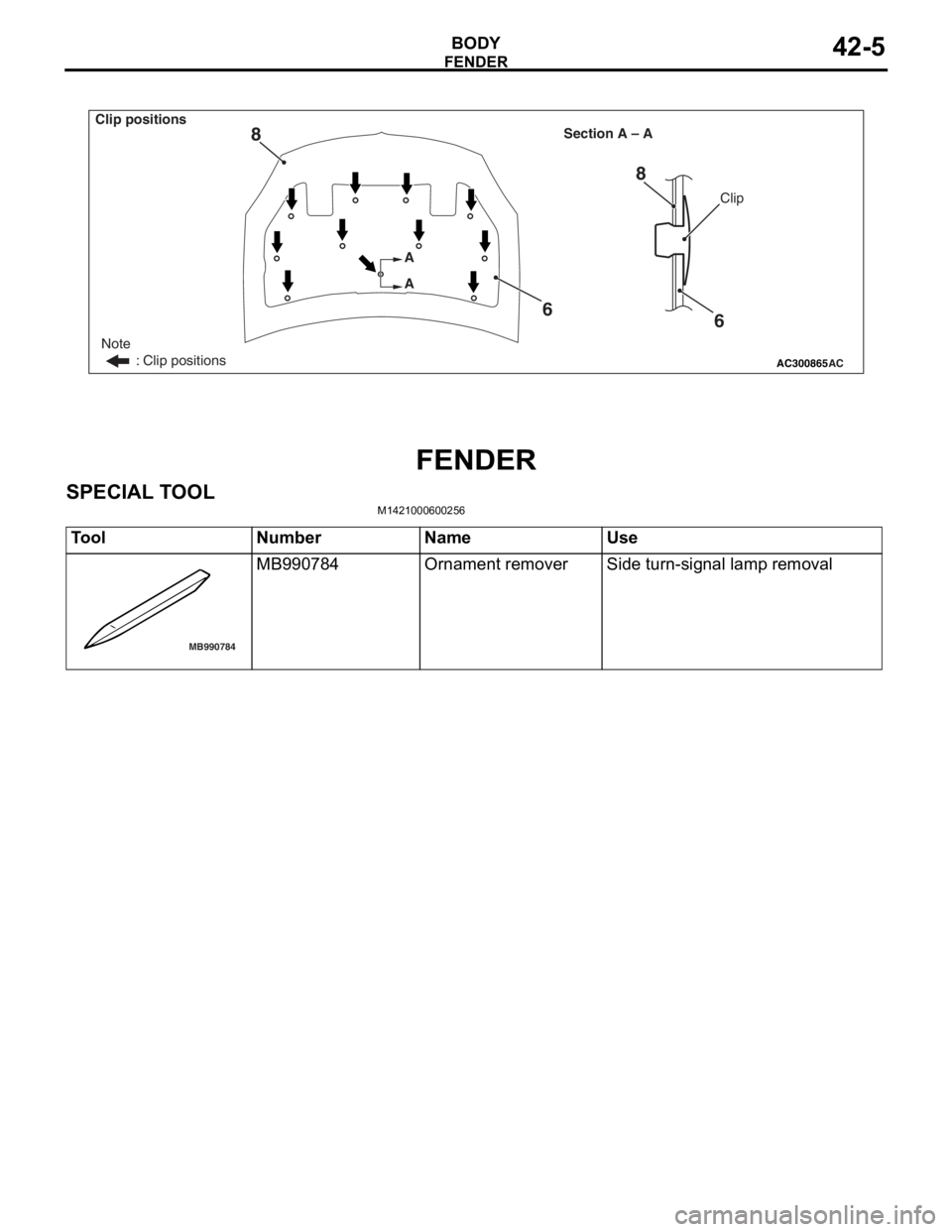
AC300865
Note
: Clip positions
Section A – A
AC
Clip
A
A
6
8
6
8
Clip positions
FEN
D ER
BOD Y42-5
FENDER
SPECIAL T O OL
M14210006 0025 6
ToolNumberNameUse
MB990784
MB990784Ornament removerSide turn-signal lamp removal
Page 278 of 800
FENDER
BODY42-6
FENDER
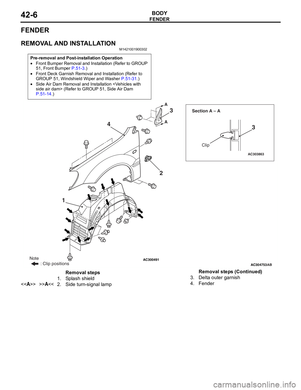
REMOVAL AND INSTALLATION
M1421001900302
Pre-removal and Post-installation Operation
•Front Bumper Removal and Installation (Refer to GROUP
51, Front Bumper P.51-3.)
•Front Deck Garnish Removal and Installation (Refer to
GROUP 51, Windshield Wiper and Washer P.51-31.)
•Side Air Dam Removal and Installation
P.51-14.)
AC300491AC304753
AC303863
Clip
Section A – A
AB
A A
1
23
3
4
Note
: Clip positions
Removal steps
1.Splash shield
<>>>A<<2.Side turn-signal lamp
3.Delta outer garnish
4.Fender
Removal steps (Continued)
Page 279 of 800
Page 360 of 800

WINDSHIELD WIPER AND WASHER
EXTERIOR51-28
WINDSHIELD WIPER AND WASHER
GENERAL INFORMATIONM1511000100514
WINDSHIELD WIPER AND WASHER
OPERATION
Windshield Low-speed (and High-speed)
Wiper Operation
•If the windshield low-speed wiper switch is turned
to the ON position with the ignition switch at the
"ACC" or "ON" position, the column switch sends
a low-speed wiper ON and high-speed wiper OFF
signals to the front-ECU. This turns the wiper sig
-
nal on and the wiper speed control relay off
(low-speed), causing the wipers to operate at
low-speed.
•If the windshield high-speed wiper switch is
turned to the ON position, the column switch
sends a low-speed wiper OFF and high-speed
wiper ON signals to the front-ECU. This turns
both the wiper signal and the wiper speed control
relay on (high-speed), causing the wipers to
operate at high-speed.
NOTE: The windshield wiper speed is switchable
with the built-in wiper speed control relay.
High-speed operations take place when the wiper
speed control relay is set to "ON" and low-speed
operations take place when the wiper speed control
relay is set to "OFF".
Windshield Intermittent Wiper Operation
The ETACS-ECU calculates the wiper operation
interval according to the voltage signal sent from the
column switch. Then the ETACS-ECU sends a signal
to the front-ECU. The front-ECU determines the
wiper operation interval and turns on the wiper relay
signal relay. This causes the wiper auto stop relay to
turn on. Then the wiper auto stop relay will turn off
after the wipers reach the park position. This causes
the wiper signal relay and then the wipers to turn off.
If the wiper signal relay remains off for the wiper
operation interval, the relay turns on again, causing
the wipers to operate in intermittent mode.
Windshield Mist Wiper Operation
•If the windshield mist wipe r switch is turned to the
ON position with the ignition switch at the "ACC"
or "ON" position, the mist wiper high-speed oper
-
ation signal is sent to the front-ECU. This signal
turns on the wiper speed control relay, causing
the wipers to work at high-speed while the mist
switch is on.
•While the windshield mist wiper switch remains
turned on when the intermittent mode is still work
-
ing, the wipers work as the mist wiper. However,
the wipers return to the intermittent mode again
when the switch is changed back to "INT" posi
-
tion.
•To prevent the windshield mist wiper from operat-
ing when the windshield wiper switch is turned
OFF, the windshield mist wiper does not work for
0.5 second after the windshi eld intermittent wiper
switch, the windshield low-speed wiper switch
and the windshield high-speed wiper switch are
turned OFF.
Windshield Washer Operation
•If the windshield washer switch is turned to ON
position with the ignition sw itch at "ACC" or "ON"
position, the windshield wa sher ON signal is sent
to the front-ECU. After 0.3 second, the windshield
wiper signal turns on. After the windshield washer
switch signal turns off, the windshield wiper signal
turns off in three seconds.
•If the windshield washer switch is turned on while
the windshield wiper is at intermittent mode,
when the windshield washer switch is turned OFF
within 0.2 second, the wiper works only once to
perform mist operation by the windshield washer
switch. When the ON condi tion of the windshield
washer switch continues more than 0.2 second,
the wiper performs the same movement as nor
-
mal condition from the time when 0.2 second has
elapsed and then returns to the intermittent
motion.
SERVICE SPECIFICATION
M1511000300325
ItemStandard value
Windshield wiper blade park position mm34 ± 5
Page 367 of 800
REAR WIPER AND WASHER
EXTERIOR51-35
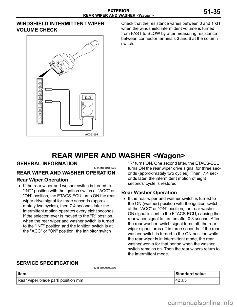
WINDSHIELD INTERMITTENT WIPER
VOLUME CHECK
1
6
8
11 10 9 7 5 4 3
2
AC201004
Ch
eck tha t the resist ance varie s between 0 a nd 1 kΩ
wh
en the
windshield int
e
rmittent volume is turn
ed
from F
A
ST
to SLOW by a
f
te
r mea
s
uring resist
an
ce
between conne
ctor
terminals 3 an
d 6 at
the column
switc
h
.
REAR WIPER AND W A SHER
GENERAL INFORMAT IONM151 1 0001 0052 5
REAR WIPER AND W A SHER OPERA T ION
Rear W i p e r O p eration
•If the rear wiper and washe r switch is turne d to
"INT" position
wit h th e ignition switch at "ACC" or
"ON" po
siti on, t he ET ACS-ECU t u rn s ON t he re ar
wipe
r drive signal for thre e se cond s (ap p roxi
-
mately two cycles), then 7 . 4 se cond s la ter the
int
e rmit tent mot i on o perates every eigh t seco nds.
If th
e se lector lever is moved to the "R" p o sition
when t
he rear wiper an d washe r switch is turn ed
to t
he "INT" position an d the ignit i on switch is at
the
"ACC" or "ON" positio n, the inhibito r switch "R" tu rns ON. One second late r , the ET ACS-ECU
turn s ON th e rear wip e r drive signal for thre e sec
-
ond
s (ap p roximat e ly two cycle s ). Th en, 7.4 sec-
onds later , th e inte rmittent motio n of eight
sec
o nds ' cy cle is restored.
Rear W a sher Operatio n
•If the rear wiper and washe r switch is turne d to
the
ON (washer) position wi th the ignition switch
at t
he "ACC" or "ON" po sit i on, t he rear wa sher
ON signal is sent to the ET
ACS-ECU, causing the
re
ar wipe r sign al to tu rn on a f ter 0 . 3 seco nd . Af te r
the
rear washer switch sign al tu rns o f f, the rear
wipe
r signa l t u rns of f in thre e seco nds. If the rear
washer switch is tu
rned to the ON position while
the
rear wipe r is in intermitten t mod e , the rear
washer works for th
at period when the washer
switch
rema ins on. Then the rea r wipe rs ret u rn to
the
intermitte nt mode.
SERV ICE SPECIFICA T ION
M151 1 0003 0033 6
ItemStandard value
Rear wiper blade park position mm42 ± 5
Page 416 of 800
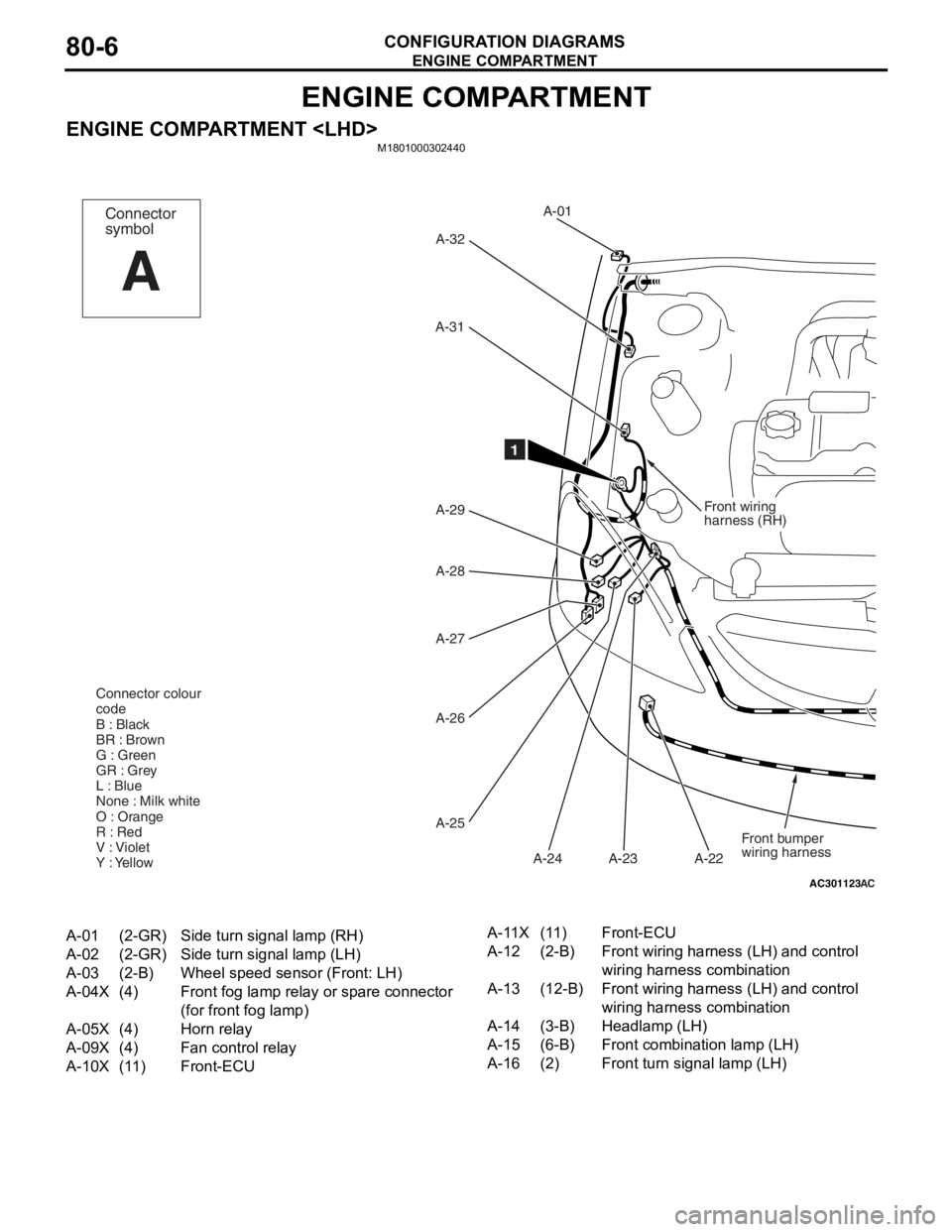
ENGINE COMPARTMENT
CONFIGURATION DIAGRAMS80-6
ENGINE COMPARTMENT
ENGINE COMPARTMENT
AC301123
Front wiring
harness (RH)
A-01
A-32
A-31
A-29
A-28
A-27
A-26
A-25 A-23
A-24 A-22
AC
1
Front bumper
wiring harness
Connector colour
code
B : Black
BR : Brown
G : Green
GR : Grey
L : Blue
None : Milk white
O : Orange
R : Red
V : Violet
Y : Yellow
Connector
symbol
A
A-01(2-GR)Side turn signal lamp (RH)
A-02(2-GR)Side turn signal lamp (LH)
A-03(2-B)Wheel speed sensor (Front: LH)
A-04X(4)Front fog lamp relay or spare connector
(for front fog lamp)
A-05X(4)Horn relay
A-09X(4)Fan control relay
A-10X(11)Front-ECU
A-11X(11)Front-ECU
A-12(2-B)Front wiring harness (LH) and control
wiring harness combination
A-13(12-B)Front wiring harness (LH) and control
wiring harness combination
A-14(3-B)Headlamp (LH)
A-15(6-B)Front combination lamp (LH)
A-16(2)Front turn signal lamp (LH)
Page 417 of 800
AC502048AB
A-02A-03
A-04X
A-05X
A-09X
A-10X
A-11X
A-12
A-13
A-14
A-15
A-16
A-17
A-18
A-19
A-20
A-21 Front wiring
harness
(LH)
12
A-33
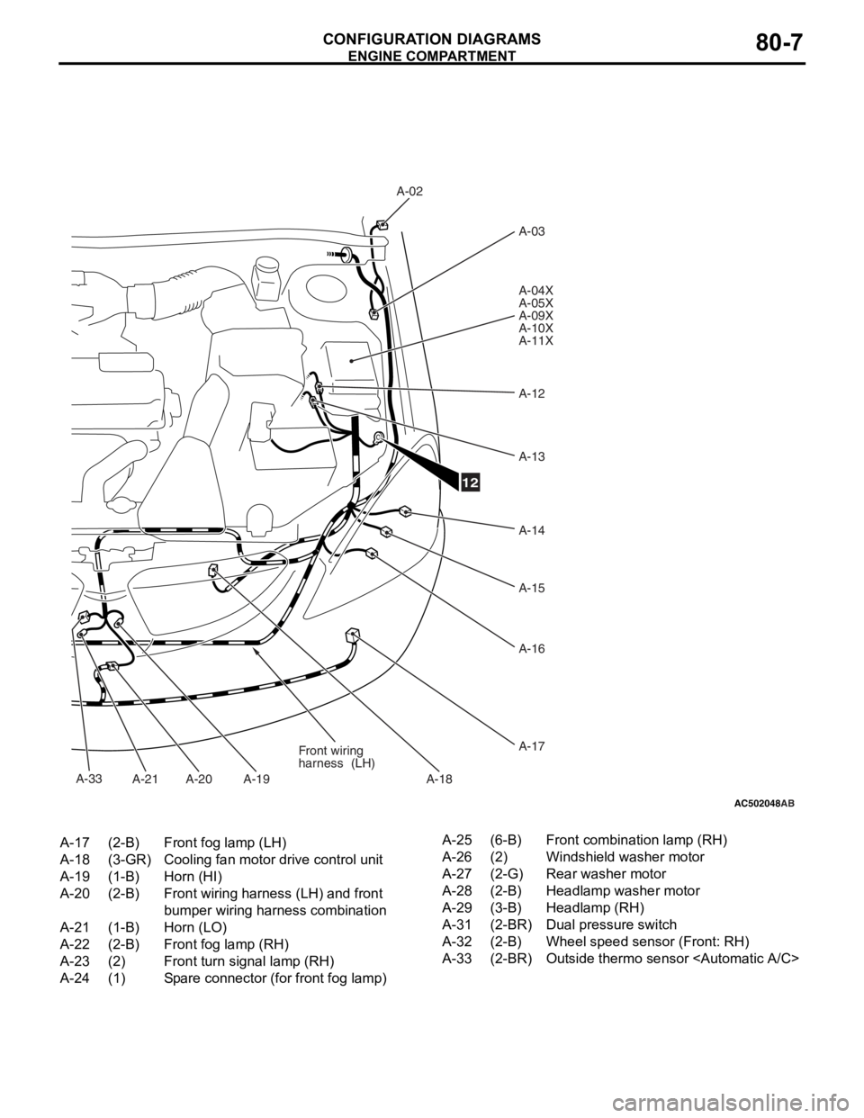
A-17(2-B)Front fog lamp (LH)
A-18(3-GR)Cooling fan motor drive control unit
A-19(1-B)Horn (HI)
A-20(2-B)Front wiring harness (LH) and front
bumper wiring harness combination
A-21(1-B)Horn (LO)
A-22(2-B)Front fog lamp (RH)
A-23(2)Front turn signal lamp (RH)
A-24(1)Spare connector (for front fog lamp)
A-25(6-B)Front combination lamp (RH)
A-26(2)Windshield washer motor
A-27(2-G)Rear washer motor
A-28(2-B)Headlamp washer motor
A-29(3-B)Headlamp (RH)
A-31(2-BR)Dual pressure switch
A-32(2-B)Wheel speed sensor (Front: RH)
A-33(2-BR)Outside thermo sensor
ENGINE COMP AR TMEN T
CONF IGURA TION D I A G RA MS80-7
Page 418 of 800
ENGINE COMPARTMENT
CONFIGURATION DIAGRAMS80-8
ENGINE COMPARTMENT
M1801000302451
AC301126
Front wiring
harness (RH)
A-01
A-32
A-31
A-29 A-30
A-27
A-26
A-25 A-23
A-24 A-22
AC
1
Front bumper
wiring harness
Connector colour
code
B : Black
BR : Brown
G : Green
GR : Grey
L : Blue
None : Milk white
O : Orange
R : Red
V : Violet
Y : Yellow
Connector
symbol
A
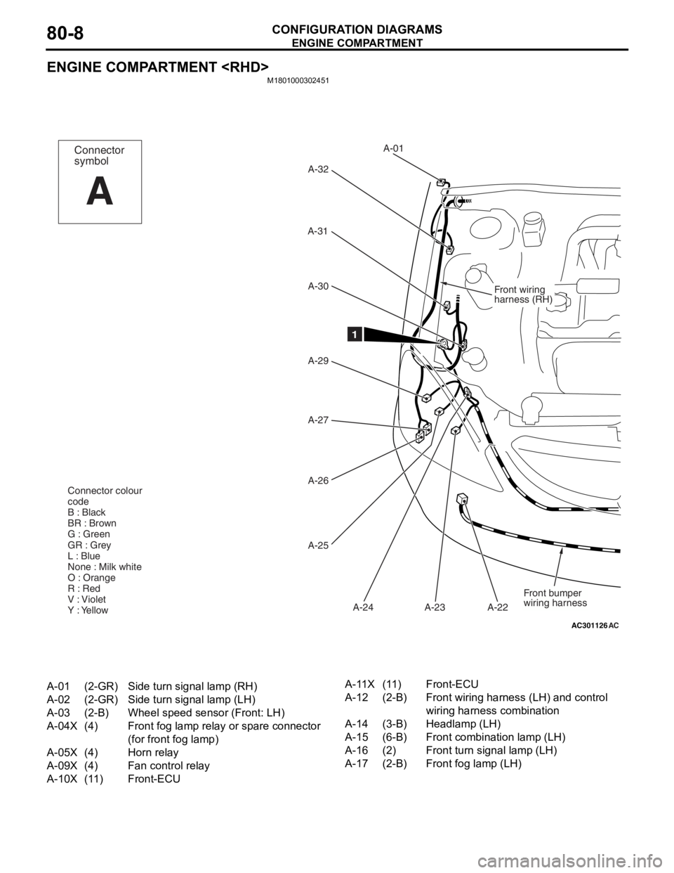
A-01(2-GR)Side turn signal lamp (RH)
A-02(2-GR)Side turn signal lamp (LH)
A-03(2-B)Wheel speed sensor (Front: LH)
A-04X(4)Front fog lamp relay or spare connector
(for front fog lamp)
A-05X(4)Horn relay
A-09X(4)Fan control relay
A-10X(11)Front-ECU
A-11X(11)Front-ECU
A-12(2-B)Front wiring harness (LH) and control
wiring harness combination
A-14(3-B)Headlamp (LH)
A-15(6-B)Front combination lamp (LH)
A-16(2)Front turn signal lamp (LH)
A-17(2-B)Front fog lamp (LH)
Page 419 of 800
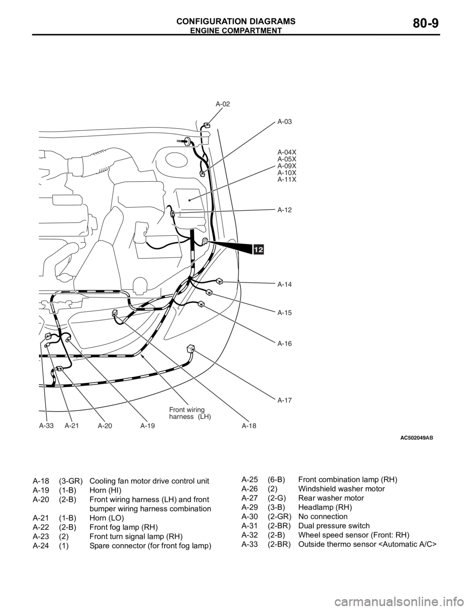
AC502049
A-33
AB
A-02A-03
A-04X
A-05X
A-09X
A-10X
A-11X
A-12
A-14
A-15
A-16
A-17
A-18
A-19
A-20
A-21 Front wiring
harness
(LH)
12
A-18(3-GR)Cooling fan motor drive control unit
A-19(1-B)Horn (HI)
A-20(2-B)Front wiring harness (LH) and front
bumper wiring harness combination
A-21(1-B)Horn (LO)
A-22(2-B)Front fog lamp (RH)
A-23(2)Front turn signal lamp (RH)
A-24(1)Spare connector (for front fog lamp)
A-25(6-B)Front combination lamp (RH)
A-26(2)Windshield washer motor
A-27(2-G)Rear washer motor
A-29(3-B)Headlamp (RH)
A-30(2-GR)No connection
A-31(2-BR)Dual pressure switch
A-32(2-B)Wheel speed sensor (Front: RH)
A-33(2-BR)Outside thermo sensor
ENGINE COMP AR TMEN T
CONF IGURA TION D I A G RA MS80-9