shocks MITSUBISHI LANCER 2006 Workshop Manual
[x] Cancel search | Manufacturer: MITSUBISHI, Model Year: 2006, Model line: LANCER, Model: MITSUBISHI LANCER 2006Pages: 800, PDF Size: 45.03 MB
Page 92 of 800

IGNITION SYSTEM
ENGINE ELECTRICAL16-30
IGNITION SYSTEM
GENERAL INFORMATIONM1163000100294
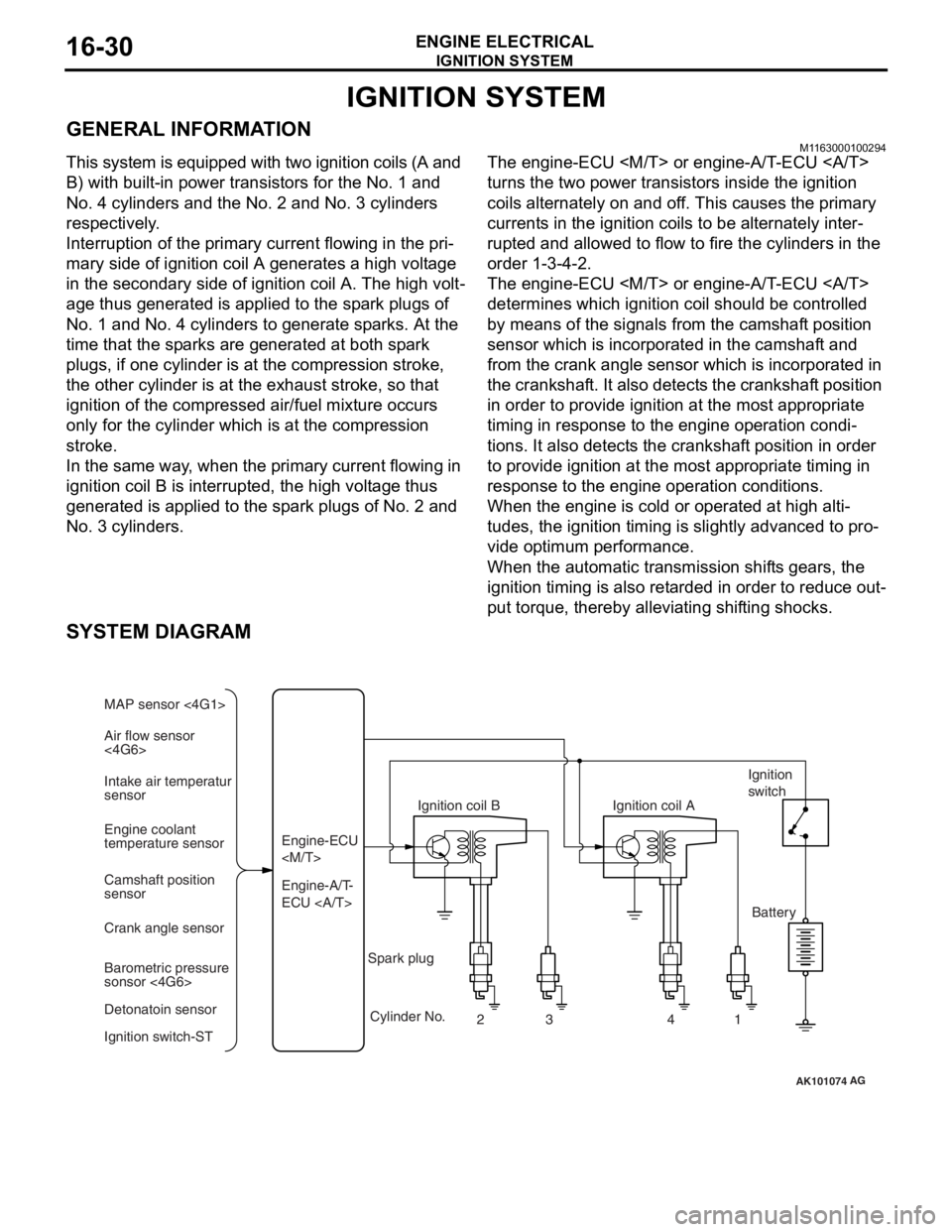
This system is equipped with two ignition coils (A and
B) with built-in power transistors for the No. 1 and
No. 4 cylinders and the No. 2 and No. 3 cylinders
respectively.
Interruption of the primary current flowing in the pri-
mary side of ignition coil A generates a high voltage
in the secondary side of ignition coil A. The high volt
-
age thus generated is applied to the spark plugs of
No. 1 and No. 4 cylinders to generate sparks. At the
time that the sparks are generated at both spark
plugs, if one cylinder is at the compression stroke,
the other cylinder is at the exhaust stroke, so that
ignition of the compressed air/fuel mixture occurs
only for the cylinder which is at the compression
stroke.
In the same way, when the primary current flowing in
ignition coil B is interrupted, the high voltage thus
generated is applied to the spark plugs of No. 2 and
No. 3 cylinders.
The engine-ECU
turns the two power transistors inside the ignition
coils alternately on and off. This causes the primary
currents in the ignition coils to be alternately inter
-
rupted and allowed to flow to fire the cylinders in the
order 1-3-4-2.
The engine-ECU
determines which ignition coil should be controlled
by means of the signals from the camshaft position
sensor which is incorporated in the camshaft and
from the crank angle sensor which is incorporated in
the crankshaft. It also detects the crankshaft position
in order to provide ignition at the most appropriate
timing in response to the engine operation condi
-
tions. It also detects the crankshaft position in order
to provide ignition at the most appropriate timing in
response to the engine operation conditions.
When the engine is cold or operated at high alti-
tudes, the ignition timing is slightly advanced to pro-
vide optimum performance.
When the automatic transmission shifts gears, the
ignition timing is also retarded in order to reduce out
-
put torque, thereby alleviating shifting shocks.
SYSTEM DIAGRAM
AK101074
Air flow sensor
<4G6> MAP sensor <4G1>
Intake air temperatur
sensor
Engine coolant
temperature sensor
Camshaft position
sensor
Crank angle sensor
Barometric pressure
sonsor <4G6>
Detonatoin sensor
Ignition switch-ST Engine-A/T-
ECU Engine-ECU
Ignition coil B
Cylinder No. 23 4
AG
1
Spark plug Ignition coil A
Ignition
switch
Battery
Page 166 of 800

TROUBLESHOOTING
WHEEL AND TYRE31-4
WHEEL BALANCE ACCURACY
M1311001700247
PURPOSE
This section contains tips and procedures for achiev-
ing accurate wheel balance. Steering wheel vibration
and/or body shake can result if any of these proce
-
dures are not carefully observed.
1. Wheels and tyres must be properly mounted on a balancer in order to achieve correct balance.
Centring the wheel on the shaft of the balancer is
essential for proper mounting.
2. Off-the-car wheel balancers must be calibrated periodically to ensure good balancing results. An
inaccurately calibrated balancer could cause
unnecessary replacement of tyres, shocks,
suspension components, or steering components.
Check your balancer's calibration approximately
every 100 balances. Your wheel balancer's instruc
-
tion manual should include calibration procedures. If
the calibration procedures specifically for your bal
-
ancer are missing, use the generic steps in this sec-
tion for zero calibration, static balance, and dynamic
balance checks. The wheel balancer calibration
checks are also described in the flowchart. (Refer to
P.31-6).
PROCEDURE
1. Confirm that the balancer's cone and the wheel
mounting cone are undamaged and free of dirt
and rust.
2. On this vehicle, the wheel's centre hole on the hub side has a chamfered edge. Use a
back-mounting cone on your wheel balancer to
centre the wheel on the balancer shaft.
3. Install a wheel mounting cone. The appropriate size cone for this vehicle is 67.0 mm.
4. Before balancing the wheel, remove any wheel weights from both sides. Also check both sides for
any damage.
5. When installing wheel weights, hammer them at a straight (not diagonal) angle.
Scalloped
wear
ACX00934
Lack of rot a tio n of tyres or worn
or out-of-a
lign m ent suspensionRota te th e tyre s, an d
check the f
r ont or
rea
r suspension
alignment
s.
Refer to GROUP
33
, On -vehicle
serv
ic e
− Front
whee
l alignment
check and
ad
justmen t
P.33-6.
Refer to GROUP
34
, On -vehicle
serv
ic e
− Rear
whee
l alignment
check and
ad
justmen t
P.34-6.
Sy mptom P robable cause Reme dy Referen ce p a g e