ignition MITSUBISHI LANCER 2014 8.G Owners Manual
[x] Cancel search | Manufacturer: MITSUBISHI, Model Year: 2014, Model line: LANCER, Model: MITSUBISHI LANCER 2014 8.GPages: 434, PDF Size: 57.5 MB
Page 348 of 434
How to change a tire
For emergencies 8-7
8
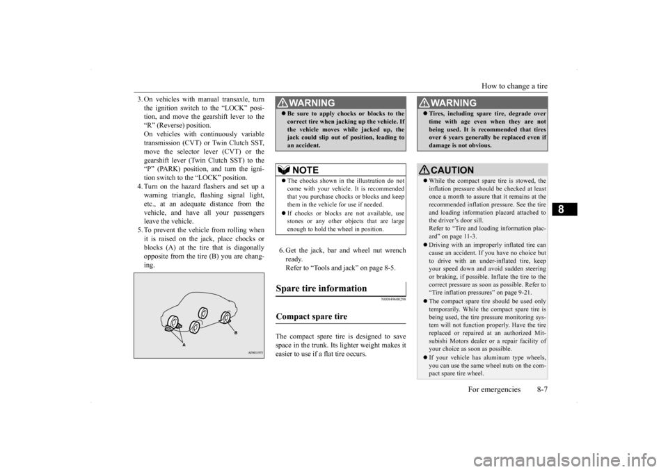
3. On vehicles with manual transaxle, turn the ignition switch to the “LOCK” posi- tion, and move the gearshift lever to the “R” (Reverse) position.On vehicles with continuously variable transmission (CVT) or Twin Clutch SST, move the selector lever (CVT) or thegearshift lever (Twin Clutch SST) to the “P” (PARK) position, and turn the igni- tion switch to the “LOCK” position.4. Turn on the hazard flashers and set up awarning triangle, flashing signal light, etc., at an adequate distance from the vehicle, and have all your passengersleave the vehicle. 5. To prevent the vehicle from rolling when it is raised on the jack, place chocks orblocks (A) at the tire that is diagonally opposite from the tire (B) you are chang- ing.
6. Get the jack, bar and wheel nut wrench ready.Refer to “Tools and jack” on page 8-5.
N00849600298
The compact spare tire is designed to savespace in the trunk. Its lighter weight makes it easier to use if a flat tire occurs.
WA R N I N G Be sure to apply chocks or blocks to the correct tire when jacking up the vehicle. If the vehicle moves while jacked up, the jack could slip out of position, leading to an accident.NOTE
The chocks shown in the illustration do not come with your vehicle. It is recommended that you purchase chocks or blocks and keepthem in the vehicle for use if needed. If chocks or blocks are not available, use stones or any other objects that are large enough to hold the wheel in position.
Spare tire information Compact spare tire
WA R N I N G Tires, including spare tire, degrade over time with age even when they are not being used. It is recommended that tires over 6 years generally be replaced even if damage is not obvious.CAUTION While the compact spare tire is stowed, the inflation pressure should be checked at least once a month to assure that it remains at therecommended inflation pressure. See the tire and loading information placard attached to the driver’s door sill.Refer to “Tire and loading information plac- ard” on page 11-3. Driving with an improperly inflated tire can cause an accident. If you have no choice but to drive with an under-inflated tire, keepyour speed down and avoid sudden steering or braking, if possible. Inflate the tire to the correct pressure as soon as possible. Refer to“Tire inflation pressures” on page 9-21. The compact spare tire should be used only temporarily. While the compact spare tire is being used, the tire pressure monitoring sys- tem will not function properly. Have the tire replaced or repaired at an authorized Mit- subishi Motors dealer or a repair facility ofyour choice as soon as possible. If your vehicle has aluminum type wheels, you can use the same wheel nuts on the com- pact spare tire wheel.
Page 356 of 434
Operation under adverse driving conditions
For emergencies 8-15
8
Place the gearshift lever in the “Neutral” position. Turn the ignition switch to the “ACC” posi-tion and secure the steering wheel in a straight-ahead position with a rope or tie- down strap. Never place the ignition switch inthe “LOCK” position when towing.
Release the parking brake. Place the gearshift lever in the “Neutral” position (manual transaxle) or the selectorlever in the “N” (NEUTRAL) position (CVT).
N00837200662
If your vehicle becomes stuck in snow, sand, or mud, it can often be moved by a rockingmotion. Rock your vehicle back and forth to free it. Do not rev the engine or spin the wheels.Constant efforts to free a stuck vehicle can cause overheating and transaxle failure. Let
Towing the vehicle by a tow truck
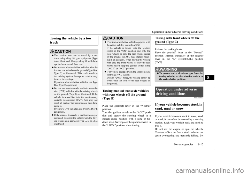
CAUTION This vehicle must not be towed by a tow truck using sling lift type equipment (TypeA) as illustrated. Using a sling lift will dam- age the bumper and front end. Do not tow all-wheel dr
ive vehicles with the
front or rear wheels on the ground (Type B or Type C) as illustrated. This could result inthe driving system damage or vehicle may jump at the carriage. If you tow all-wheel drive vehicles, use TypeD or Type E equipment. Do not tow continuously variable transmis- sion (CVT) vehicles with the driving wheels on the ground (Type B) as illustrated. If the vehicle is towed like this, the continuouslyvariable transmission (CVT) fluid may not reach all parts of the transmission, thus dam- aging it.If you tow CVT vehicles, use Type C, D or E equipment. If the manual transaxle is malfunctioning or damaged, transport the vehicle with the driv- ing wheels on a carriage (Type C, D or E) as illustrated.
[For front-wheel drive vehicle equipped with the active stability control (ASC)] If the vehicle is towed with the ignition switch in the “ON” position and only the front wheels or only the rear wheels raisedoff the ground, the ASC may operate, result- ing in an accident. When towing the vehicle with only the front wheels or only the rearwheels raised, keep the ignition switch in the “LOCK” or “ACC” position. [For vehicle equipped with the Electronically controlled 4WD system] Even in “2WD” mode, the vehicle cannot betowed with the front or the rear wheels on the ground.
Towing manual transaxle vehicles with rear wheels off the ground (Type B)
CAUTION
Towing with front wheels off the ground (Type C)
WA R N I N G To prevent entry of exhaust gas from the towing vehicle, set the selection switch to the recirculation position.
Operation under adverse driving conditions If your vehicle becomes stuck in sand, mud or snow
Page 362 of 434
Engine hood
Vehicle care and maintenance 9-3
9
To reduce the possibility of catalytic con- verter damage: Use UNLEADED GASOLINE ONLY of the type of recommended in “Fuel selec- tion”. Do not drive with an extremely low fuel level. Running out of gas could damage the catalytic converter. Do not try to start the engine by pushing or towing the vehicle. If the battery is weak or run down, use jumper cables to properly start the engine.
Do not idle the engine with any spark plug wires disconnected or removed, such as when performing diagnostic tests. Do not idle the engine for a long time if it is idling roughly or otherwise obviously malfunctioning. To prevent the catalytic converter from being damaged from unburned gas, do not race the engine when turning off the igni- tion switch. Stop driving the vehicle if you think the performance is less than normal, the engine is running oddly or there is any other engine trouble, such as with theignition, etc. If you
are not able to stop
driving immediately, slow down and drive for only a short time. Have an inspectionmade by an authorized Mitsubishi Motors dealer or a repair facility of your choice as soon as possible. In unusual situations involving major engine problems, a burning odor may indicate severe and abnormal catalyticconverter overheating. If this occurs, stop in a safe place, shut the engine off and let the vehicle cool. Once the engine is cool,immediately take your vehicle to a dealer or a repair facility of your choice for ser- vice.
N00937500464
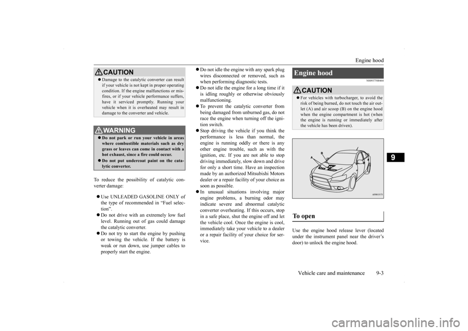
Use the engine hood release lever (locatedunder the instrument panel near the driver’s door) to unlock the engine hood.
CAUTION Damage to the catalytic converter can result if your vehicle is not kept in proper operating condition. If the engine malfunctions or mis- fires, or if your vehicle performance suffers, have it serviced promptly. Running yourvehicle when it is overheated may result in damage to the converter and vehicle.WA R N I N G Do not park or run your vehicle in areas where combustible materials such as dry grass or leaves can come in contact with a hot exhaust, since a fire could occur. Do not put undercoat paint on the cata- lytic converter.
Engine hood
CAUTION For vehicles with turbocharger, to avoid the risk of being burned, do not touch the air out- let (A) and air scoop (B) on the engine hood when the engine compartment is hot (whenthe engine is running or immediately after the vehicle has been driven).
To open
Page 371 of 434
Transfer oil (All-wheel drive models) 9-12 Vehicle care and maintenance
9
Mitsubishi Motors Corporation does not rec- ommend the addition of any fluid additives tothe transmission.
N00938400239
Whenever the transfer oil level is checked,add oil as necessary to maintain the properlevel. Fill or change the oil according to the table.
N00915200227
Whenever the oil level is checked, add oil as necessary to maintain the proper level. Fill or change oil according to the table.
N00915300026
Remove the lid on the trunk room right sidetrim. Check the fluid level in the reservoir 90 min-utes or more after turning the ignition switch to the “LOCK” position. Check to make certain that the AWC controlfluid level is always between the “MAX” and “MIN” level markings on the fluid reservoir and refill the fluid, if necessary.
N00938600273
The windshield washer fluid reservoir is inthe engine compartment.
Special additives
Transfer oil (All-wheel drive models) Oil type Lubri- cant
Mitsubishi Motors Genuine LSD
gear oil or equivalent
Rear axle oil (All-wheel drive models)
Oil type Lubri- cant
Mitsubishi Motors Genuine LSD
gear oil or equivalent
AWC control fluid
(if so
equipped)To check the fluid level
Fluid type
Lubricant DIAMOND ATF SP IIIWasher fluid
Page 373 of 434
Power steering fluid (if so equipped) 9-14 Vehicle care and maintenance
9
N00939000388
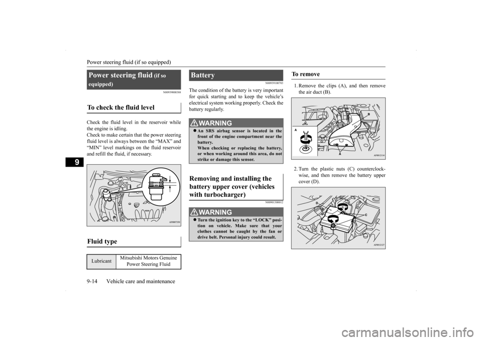
Check the fluid level in the reservoir while the engine is idling. Check to make certain that the power steering fluid level is always between the “MAX” and“MIN” level markings on the fluid reservoirand refill the fluid, if necessary.
N00939100783
The condition of the battery is very importantfor quick starting and to keep the vehicle’selectrical system working properly. Check the battery regularly.
N00901300012
1. Remove the clips (A), and then removethe air duct (B). 2. Turn the plastic nuts (C) counterclock- wise, and then remove the battery uppercover (D).
Power steering fluid
(if so
equipped)To check the fluid level
Fluid type
Lubricant
Mitsubishi Motors Genuine
Power Steering Fluid
Battery
WA R N I N G An SRS airbag sensor is located in the front of the engine compartment near the battery. When checking or replacing the battery,or when working around this area, do not strike or damage this sensor.
Removing and installing the battery upper cover (vehicles with turbocharger)
WA R N I N G Turn the ignition key to the “LOCK” posi- tion on vehicle. Make sure that your clothes cannot be caught by the fan or drive belt. Personal injury could result.
To remove
Page 385 of 434
General maintenance 9-26 Vehicle care and maintenance
9
N00940900215
Spark plugs must fire properly for good engine performance and emission-control.Do not reuse them by cleaning or regapping. Change them at the mileage listed in the “WARRANTY AND MAINTENANCEMANUAL”.
N00941000037
Check the hose surfaces for any heat andmechanical damage, hard and brittle rubber,cracking, tears, cuts and abrasions. Pay spe- cial attention to the hoses closest to high heat sources such as the exhaust manifold. Checkall the hose connections, such as clamps and couplings, to make sure they are secure and that there are no leaks. If you see any wear ordamage, replace the hoses immediately.
N00950100050
Have the valve clearance checked at anauthorized Mitsubishi Motors dealer at themileage specified in the “WARRANTY AND MAINTENANCE MANUAL”. If the engine sounds abnormally loud, haveadjustments made by an authorized Mitsubishi Motors dealer.
N00941300085
Check these regularly for damage or leaks in the fuel lines and connections. Check the fuel tank filler cap for damage or looseness. Pay special attention to the fuel lines closest to
high heat sources such as the exhaust mani- fold.
N00941400116
If the fuel-vapor vent line is clogged or dam- aged, the fuel-vapor mixture will escape, pol- luting the air.Have the system checked at an authorized Mitsubishi Motors dealer at the mileage spec- ified in the “WARRANTY AND MAINTE-NANCE MANUAL”.
N00941500159
The next pages list the maintenance servicerecommended by Mitsubishi Motors Corpo- ration. In addition to the general maintenance that needs to be performed at the times listed,
NOTE
To meet government regulations and pro- mote cleaner air, your vehicle is equipped with an onboard diagnostic system (OBD). The engine electronic control module that controls OBD functions stores various data(especially about the exhaust emissions). This data will be erased if the battery cable is disconnected, which could make a rapiddiagnosis difficult. Do not disconnect the battery cable when the engine malfunction indicator (“SERVICE ENGINE SOON” or“Check engine light”) is on.
Spark plugs
NOTE
Use the spark plugs listed under “Engine specifications” on page 11-5 or plugs that are exactly the same. Other plugs could causeengine damage, performance problems or radio noise.
Fuel hoses Intake valve clearance Fuel system (tank, pipe line and connection, and fuel tank filler cap)
WA R N I N G If you see a fuel leak or if you smell fuel, do not run the engine. Any spark (includ- ing from the ignition), flame or smokingmaterial could cause an explosion or fire. Call an authorized Mitsubishi Motors dealer or a repair facility of your choicefor assistance.
Evaporative emission control system (except evaporative emission canister) General maintenance
Page 389 of 434
Fuses 9-30 Vehicle care and maintenance
9
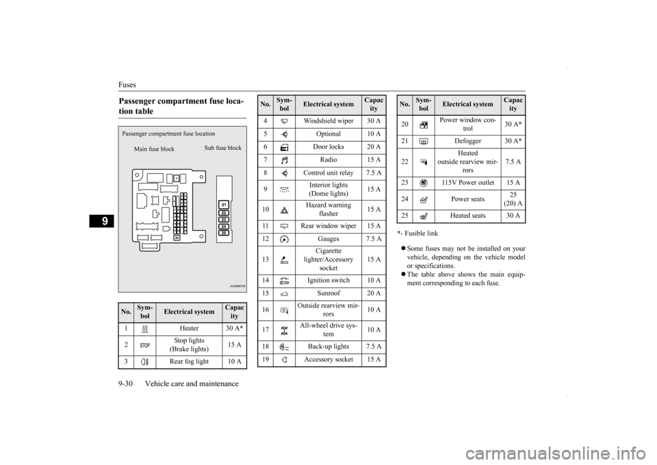
* - Fusible link Some fuses may not be installed on your vehicle, depending on the vehicle model or specifications. The table above shows the main equip- ment corresponding to each fuse.
Passenger compartment fuse loca- tion table No.
Sym- bol
Electrical system
Capacity
1 Heater 30 A
*
2
Stop lights (Brake lights)
15 A
3 Rear fog light 10 A
Main fuse block
Sub fuse block
Passenger compartme
nt fuse location
4 Windshield wiper 30 A 5 Optional 10 A 6 Door locks 20 A 7 Radio 15 A8 Control unit relay 7.5 A 9
Interior lights (Dome lights)
15 A
10
Hazard warning
flasher
15 A
11 Rear window wiper 15 A 12 Gauges 7.5 A 13
Cigarette
lighter/Accessory
socket
15 A
14 Ignition switch 10 A 15 Sunroof 20 A 16
Outside rearview mir-
rors
10 A
17
All-wheel drive sys-
tem
10 A
18 Back-up lights 7.5 A 19 Accessory socket 15 ANo.
Sym- bol
Electrical system
Capacity
20
Power window con-
trol
30 A
*
21 Defogger 30 A
*
22
Heated
outside rearview mir-
rors
7.5 A
23 115V Power outlet 15 A 24 Power seats
25 (20) A
25 Heated seats 30 ANo.
Sym- bol
Electrical system
Capacity
Page 390 of 434
Fuses
Vehicle care and maintenance 9-31
9
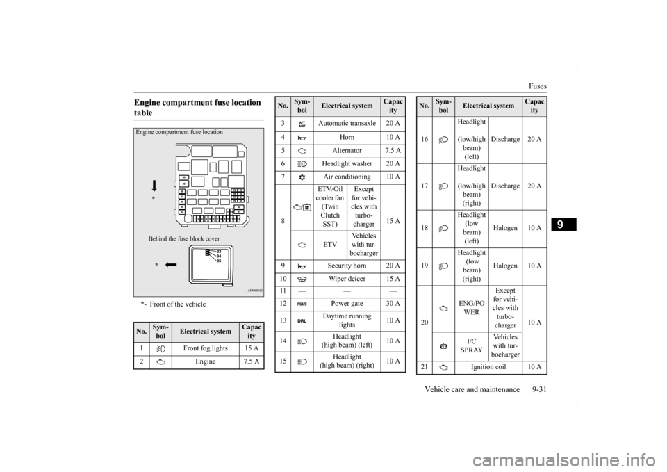
Engine compartment fuse location table * - Front of the vehicle
No.
Sym- bol
Electrical system
Capacity
1 Front fog lights 15 A 2 Engine 7.5 AEngine compartment fuse location
* Behind the fuse
block cover
*
3 Automatic transaxle 20 A 4 Horn 10 A 5 Alternator 7.5 A 6 Headlight washer 20 A 7 Air conditioning 10 A 8
/
ETV/Oil cooler fan (Twin Clutch SST)
Except for vehi- cles with turbo- charger
15 A
ETV
Vehicles with tur-bocharger
9 Security horn 20 A 10 Wiper deicer 15 A 11 — — — 12 Power gate 30 A 13
Daytime running
lights
10 A
14
Headlight
(high beam) (left)
10 A
15
Headlight
(high beam) (right)
10 A
No.
Sym- bol
Electrical system
Capacity
16
Headlight
(low/high beam) (left)
Discharge 20 A
17
Headlight
(low/high beam) (right)
Discharge 20 A
18
Headlight (low beam) (left)
Halogen 10 A
19
Headlight (low beam) (right)
Halogen 10 A
20
ENG/PO WER
Except for vehi- cles with turbo- charger
10 A
I/C SPRAY
Vehicles with tur-bocharger
21 Ignition coil 10 ANo.
Sym- bol
Electrical system
Capacity
Page 391 of 434
Fuses 9-32 Vehicle care and maintenance
9
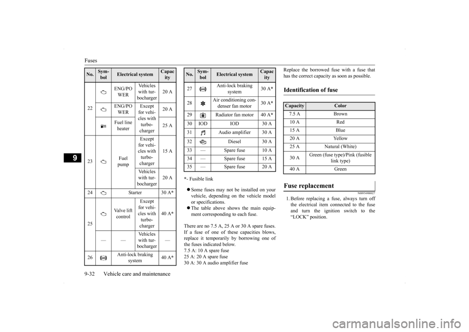
* - Fusible link Some fuses may not be installed on your vehicle, depending on the vehicle modelor specifications. The table above shows the main equip- ment corresponding to each fuse.
There are no 7.5 A, 25 A or 30 A spare fuses. If a fuse of one of these capacities blows,replace it temporarily by borrowing one of the fuses indicated below. 7.5 A: 10 A spare fuse25 A: 20 A spare fuse 30 A: 30 A audio amplifier fuse
Replace the borrowed fuse with a fuse that has the correct capacity as soon as possible.
N00954900027
1. Before replacing a fuse, always turn offthe electrical item connected to the fuseand turn the ignition switch to the“LOCK” position.
22
ENG/PO WER
Vehicles with tur-bocharger
20 A
ENG/PO WER
Except for vehi- cles with turbo- charger
20 A
Fuel line heater
25 A
23
Fuel pump
Except for vehi-cles with turbo- charger
15 A
Vehicles with tur- bocharger
20 A
24 Starter 30 A
*
25
Valve lift control
Except for vehi- cles with turbo- charger
40 A
*
——
Vehicles with tur-bocharger
—
26
Anti-lock braking
system
40 A
*
No.
Sym- bol
Electrical system
Capacity
27
Anti-lock braking
system
30 A
*
28
Air conditioning con- denser fan motor
30 A
*
29 Radiator fan motor 40 A
*
30 IOD IOD 30 A31 Audio amplifier 30 A 32 Diesel 30 A 33 — Spare fuse 10 A 34 — Spare fuse 15 A35 — Spare fuse 20 ANo.
Sym- bol
Electrical system
Capacity
Identification of fuse Capacity
Color
7.5 A Brown10 A Red15 A Blue20 A Yellow25 A Natural (White) 30 A
Green (fuse type)/Pink (fusible
link type)
40 A Green
Fuse replacement
Page 428 of 434
Alphabetical index
12-3
12
Front turn signal lights
Replacement
.................
.................
9-40
Front turn signal, parking and side-marker lightsBulb capacity
................
.................
9-34
Replacement
.................
.................
9-39
Fuel
Fuel economy
...................
................
6-2
Fuel hoses
.....................
.................
9-26
Modification/alterations to the electrical orfuel systems
...................
................
3-6
Tank capacity
..........................
3-4
, 11-6
Fuel selection
....................
...................
3-2
Fuses
.........................
........................
9-28
Fusible links
..................
.....................
9-28
G
General maintenance
...........................
9-26
General vehicle data
............................
11-4
Genuine parts
....................
...................
3-7
Glove compartment
...........................
5-190
H
Hazard warning flasher switch
...........
5-155
Hazard warning lights
.......................
5-145
Head restraints
...................
...................
4-6
Headlight leveling switch
..................
5-154
Headlights
Bulb capacity
..................
...............
9-34
Dimmer
...................
.....................
5-152
Headlight flasher
...........................
5-152
Leveling switch
.............................
5-154
Replacement
...................
...............
9-36
Switch
.....................
.....................
5-149
Heater without air conditioning function
.7-4
High beam indicator
..........................
5-145
Hill start assist (vehicles with Twin Clutch SST)
.........................
......................
5-91
Hood lock release mechanism and safety catch
.........................
......................
9-28
Horn switch
.....................
.................
5-161
I
If the vehicle breaks down
.....................
8-2
Ignition switch
...........................
5-16
, 5-54
Important facts to know in case of an accident 10-4 Indicators
....................
.....................
5-145
Information screen display
.................
5-147
Inside day/night rearview mirror
..........
5-51
Inside emergency trunk lid release
.......
5-42
Interior lights
...................
.................
5-188
J
Jack
...........................
..........................
8-6
Storage
.........................
...................
8-5
Jump-starting the engine
........................
8-2
K
Key reminder buzzer
...........................
5-37
Keyless entry system
.............................
5-7
Keys
..........................
..........................
5-3
L
Labeling
........................
.....................
11-2
License plate light
Bulb capacity
................
.................
9-34
Replacement
..................
.................
9-45
Limited-slip differential
.......................
5-90
Link System
..................
...................
5-161
Loading information
..............................
6-7
Lubricants
.....................
.....................
11-6
Luggage floor boxes
..........................
5-192
M
Malfunction indicator
........................
5-146
Manual air conditioning
.......................
7-12
Manual transaxle
................
.................
5-60
Oil
.....................
...................
9-11
, 11-6