steering MITSUBISHI LANCER 2014 8.G Workshop Manual
[x] Cancel search | Manufacturer: MITSUBISHI, Model Year: 2014, Model line: LANCER, Model: MITSUBISHI LANCER 2014 8.GPages: 434, PDF Size: 57.5 MB
Page 343 of 434
If the vehicle breaks down 8-2 For emergencies
8
N00836300161
If your vehicle breaks down on the road, move to the shoulder and turn on the hazardwarning flashers. If there is no shoulder, or the shoulder is not safe, drive in the right lane slowly, with the hazard lights flashing, untilyou come to a safe stopping place. Keep the flashers flashing. If the engine stops, there will be no power assist to the steering and brakes, making these difficult to use. The brake booster will not work, so the brakes will not grip well. The brake pedalwill be harder to press than usual. Since there is no power steering assist, the steering wheel will be hard to turn.
Get help from your passengers, bystanders, etc. to push the vehicl
e and move it to a safe
zone.
N00836400713
If the engine cannot be started because the battery is weak or dead, you can start it withthe battery from another vehicle using jumper cables. 1. Take off any metal jewelry such as watch bands or bracelets that might make an accidental electrical contact.
2. Position the vehicles close enough together so that the jumper cables can reach, but be sure the vehicles aren’t touching each other. 3. You could be injured if the vehicles move. Set the parking brake firmly on each vehi- cle. Put an automatic transaxle, CVT or Twin Clutch SST in “P” (PARK) or amanual transaxle in “N” (Neutral). Turn the ignition key to the “LOCK” position.
If the vehicle breaks down If the engine stops/fails When the engine fails at the intersection
Jump-starting the engine
WA R N I N G When using jumper cables to start a vehi- cle, follow the procedures and be very cau- tious. CAUTION Do not try to start your vehicle by pushing or towing. Vehicles with continuously variable transmission (CVT) or Twin Clutch SST cannot be started this way. Pushing or towinga vehicle that has a manual transaxle may overheat and damage the catalytic converter. Also, there is more ri
sk of an accident when
a vehicle is being pushed or towed.
CAUTION Check the other vehicle. It must have a 12- volt battery. If the other system isn’t 12-volt, both systems can be damaged.WA R N I N G Turn the ignition key to the “LOCK” posi- tion on both vehicles. Make sure that the cables or your clothes cannot be caught by the fan or drive belt. Personal injurycould result. NOTE
Turn off all lights, heater, and other electrical loads. This will avoid sparks and help save both batteries.
Page 348 of 434
How to change a tire
For emergencies 8-7
8
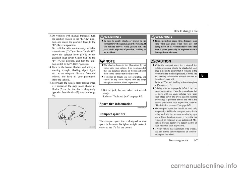
3. On vehicles with manual transaxle, turn the ignition switch to the “LOCK” posi- tion, and move the gearshift lever to the “R” (Reverse) position.On vehicles with continuously variable transmission (CVT) or Twin Clutch SST, move the selector lever (CVT) or thegearshift lever (Twin Clutch SST) to the “P” (PARK) position, and turn the igni- tion switch to the “LOCK” position.4. Turn on the hazard flashers and set up awarning triangle, flashing signal light, etc., at an adequate distance from the vehicle, and have all your passengersleave the vehicle. 5. To prevent the vehicle from rolling when it is raised on the jack, place chocks orblocks (A) at the tire that is diagonally opposite from the tire (B) you are chang- ing.
6. Get the jack, bar and wheel nut wrench ready.Refer to “Tools and jack” on page 8-5.
N00849600298
The compact spare tire is designed to savespace in the trunk. Its lighter weight makes it easier to use if a flat tire occurs.
WA R N I N G Be sure to apply chocks or blocks to the correct tire when jacking up the vehicle. If the vehicle moves while jacked up, the jack could slip out of position, leading to an accident.NOTE
The chocks shown in the illustration do not come with your vehicle. It is recommended that you purchase chocks or blocks and keepthem in the vehicle for use if needed. If chocks or blocks are not available, use stones or any other objects that are large enough to hold the wheel in position.
Spare tire information Compact spare tire
WA R N I N G Tires, including spare tire, degrade over time with age even when they are not being used. It is recommended that tires over 6 years generally be replaced even if damage is not obvious.CAUTION While the compact spare tire is stowed, the inflation pressure should be checked at least once a month to assure that it remains at therecommended inflation pressure. See the tire and loading information placard attached to the driver’s door sill.Refer to “Tire and loading information plac- ard” on page 11-3. Driving with an improperly inflated tire can cause an accident. If you have no choice but to drive with an under-inflated tire, keepyour speed down and avoid sudden steering or braking, if possible. Inflate the tire to the correct pressure as soon as possible. Refer to“Tire inflation pressures” on page 9-21. The compact spare tire should be used only temporarily. While the compact spare tire is being used, the tire pressure monitoring sys- tem will not function properly. Have the tire replaced or repaired at an authorized Mit- subishi Motors dealer or a repair facility ofyour choice as soon as possible. If your vehicle has aluminum type wheels, you can use the same wheel nuts on the com- pact spare tire wheel.
Page 353 of 434
How to change a tire 8-12 For emergencies
8
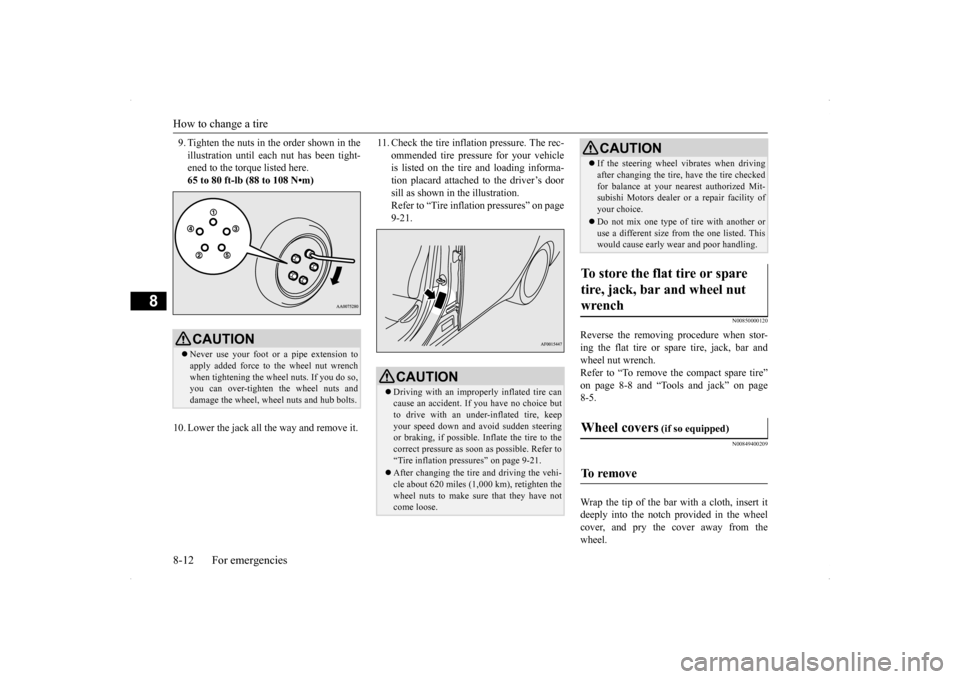
9. Tighten the nuts in the order shown in the illustration until each nut has been tight- ened to the torque listed here. 65 to 80 ft-lb (88 to 108 N•m)
10. Lower the jack all the way and remove it.
11. Check the tire inflation pressure. The rec-
ommended tire pressure for your vehicle is listed on the tire and loading informa- tion placard attached to the driver’s doorsill as shown in the illustration. Refer to “Tire inflation pressures” on page 9-21.
N00850000120
Reverse the removing procedure when stor-ing the flat tire or spare tire, jack, bar and wheel nut wrench. Refer to “To remove the compact spare tire”on page 8-8 and “Tools and jack” on page 8-5.
N00849400209
Wrap the tip of the bar with a cloth, insert it deeply into the notch provided in the wheelcover, and pry the cover away from the wheel.
CAUTION Never use your foot or a pipe extension to apply added force to the wheel nut wrench when tightening the wheel nuts. If you do so, you can over-tighten the wheel nuts anddamage the wheel, wheel nuts and hub bolts.
CAUTION Driving with an improperly inflated tire can cause an accident. If
you have no choice but
to drive with an under-inflated tire, keep your speed down and avoid sudden steering or braking, if possible. Inflate the tire to thecorrect pressure as soon as possible. Refer to “Tire inflation pressures” on page 9-21. After changing the tire and driving the vehi- cle about 620 miles (1,000 km), retighten the wheel nuts to make sure that they have notcome loose.
If the steering wheel vibrates when driving after changing the tire, have the tire checked for balance at your nearest authorized Mit- subishi Motors dealer or a repair facility of your choice. Do not mix one type of tire with another or use a different size from the one listed. Thiswould cause early wear and poor handling.
To store the flat tire or spare tire, jack, bar and wheel nut wrench Wheel covers
(if so equipped)
To remove
CAUTION
Page 356 of 434
Operation under adverse driving conditions
For emergencies 8-15
8
Place the gearshift lever in the “Neutral” position. Turn the ignition switch to the “ACC” posi-tion and secure the steering wheel in a straight-ahead position with a rope or tie- down strap. Never place the ignition switch inthe “LOCK” position when towing.
Release the parking brake. Place the gearshift lever in the “Neutral” position (manual transaxle) or the selectorlever in the “N” (NEUTRAL) position (CVT).
N00837200662
If your vehicle becomes stuck in snow, sand, or mud, it can often be moved by a rockingmotion. Rock your vehicle back and forth to free it. Do not rev the engine or spin the wheels.Constant efforts to free a stuck vehicle can cause overheating and transaxle failure. Let
Towing the vehicle by a tow truck
CAUTION This vehicle must not be towed by a tow truck using sling lift type equipment (TypeA) as illustrated. Using a sling lift will dam- age the bumper and front end. Do not tow all-wheel dr
ive vehicles with the
front or rear wheels on the ground (Type B or Type C) as illustrated. This could result inthe driving system damage or vehicle may jump at the carriage. If you tow all-wheel drive vehicles, use TypeD or Type E equipment. Do not tow continuously variable transmis- sion (CVT) vehicles with the driving wheels on the ground (Type B) as illustrated. If the vehicle is towed like this, the continuouslyvariable transmission (CVT) fluid may not reach all parts of the transmission, thus dam- aging it.If you tow CVT vehicles, use Type C, D or E equipment. If the manual transaxle is malfunctioning or damaged, transport the vehicle with the driv- ing wheels on a carriage (Type C, D or E) as illustrated.
[For front-wheel drive vehicle equipped with the active stability control (ASC)] If the vehicle is towed with the ignition switch in the “ON” position and only the front wheels or only the rear wheels raisedoff the ground, the ASC may operate, result- ing in an accident. When towing the vehicle with only the front wheels or only the rearwheels raised, keep the ignition switch in the “LOCK” or “ACC” position. [For vehicle equipped with the Electronically controlled 4WD system] Even in “2WD” mode, the vehicle cannot betowed with the front or the rear wheels on the ground.
Towing manual transaxle vehicles with rear wheels off the ground (Type B)
CAUTION
Towing with front wheels off the ground (Type C)
WA R N I N G To prevent entry of exhaust gas from the towing vehicle, set the selection switch to the recirculation position.
Operation under adverse driving conditions If your vehicle becomes stuck in sand, mud or snow
Page 360 of 434
9
Vehicle care and maintenanceService precautions ..........
.................................................................9-2
Catalytic converter .
.................................................
..........................9-2
Engine hood ...............................
.......................................................9-3
View of the engine co
mpartment ......................................................9-5
Engine oil and oil filt
er ...........................................
..........................9-6
Engine coolant .................
.................................................................9-8
Air cleaner filter.....
.................................................
..........................9-9
Manual transaxle oil (if so
equipped) ............................................. 9-11
Continuously variable transmission
(CVT) fluid (if so equipped) . 9-11
Twin Clutch Sportronic shift trans
mission (Twin Clutch SST) fluid (if
so equipped) ...........................
..................................................... 9-11
Transfer oil (All-wheel dr
ive models) ............................................9-12
Rear axle oil (All-wheel dr
ive models) .........................................9-12
AWC control fluid (if so
equipped) ................................................9-12
Washer fluid .....................
...............................................................9-12
Brake fluid/Clutch fluid (if
so equipped)........................................9-13
Power steering fluid (if so equipped)..............................................9-14 Battery........................................
.....................................................9-14
Tires ...........................................
.....................................................9-17
Clutch pedal free play (if so equipped)...........................................9-24 Brake pedal free play
..............................................
........................9-24
Parking brake lever stroke ..............................................................9-24Parking brake break-in
...........................................
........................9-25
Wiper blades ..............................
.....................................................9-25
Emission-control system maintenance ...........................................9-25 General maintenance
..............................................
........................9-26
For cold and snowy weat
her ..........................................................9-28
Fusible links .....................
...............................................................9-28
Fuses ...................................................
............................................ 9-28
Replacement of light bul
bs ....................................
......................... 9-33
Vehicle care precautions
........................................
......................... 9-48
Cleaning the inside of you
r vehicle ................................................ 9-48
Cleaning the outside of your
vehicle .............................................. 9-49
Page 364 of 434
View of the engine compartment
Vehicle care and maintenance 9-5
9
Unlatch the prop from the engine hood and put it back in its retainer. Slowly lower the engine hood about 8 inches (20 cm), then let it drop from its own weight.
N00937600667
To close
CAUTION Be careful not to trap your hands or fingers when closing the engine hood. Make sure the engine hood is firmly closed before driving. If you drive without the engine hood com-pletely closed, it could open up while driv- ing.NOTE
If this does not close the engine hood prop- erly, drop it again from a slightly higher position.
Do not push down strongly on the engine hood. Depending on how strongly or where you push down, you could create a dent in the vehicle body. For vehicles equipped with the theft-alarm system, if you drive with the engine hood left open, warning display is displayed on theinformation screen in the multi-information display.Type 1 Type 2
NOTE
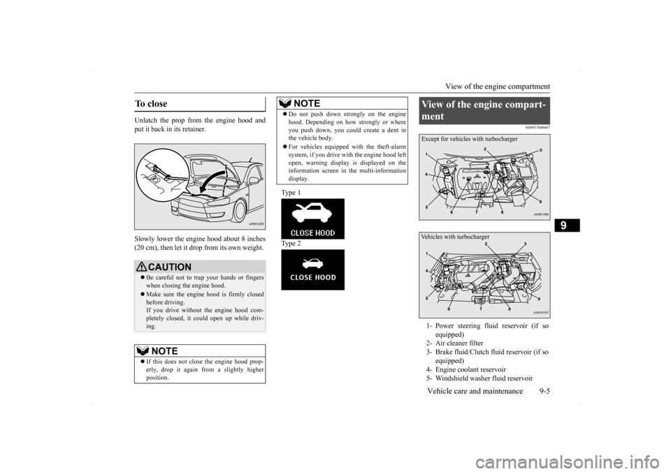
View of the engine compart- ment 1- Power steering fluid reservoir (if so
equipped)
2- Air cleaner filter 3- Brake fluid/Clutch fluid reservoir (if so
equipped)
4- Engine coolant reservoir 5- Windshield washer fluid reservoirExcept for vehicles with turbochargerVehicles with turbocharger
Page 373 of 434
Power steering fluid (if so equipped) 9-14 Vehicle care and maintenance
9
N00939000388
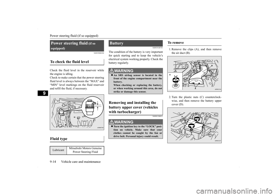
Check the fluid level in the reservoir while the engine is idling. Check to make certain that the power steering fluid level is always between the “MAX” and“MIN” level markings on the fluid reservoirand refill the fluid, if necessary.
N00939100783
The condition of the battery is very importantfor quick starting and to keep the vehicle’selectrical system working properly. Check the battery regularly.
N00901300012
1. Remove the clips (A), and then removethe air duct (B). 2. Turn the plastic nuts (C) counterclock- wise, and then remove the battery uppercover (D).
Power steering fluid
(if so
equipped)To check the fluid level
Fluid type
Lubricant
Mitsubishi Motors Genuine
Power Steering Fluid
Battery
WA R N I N G An SRS airbag sensor is located in the front of the engine compartment near the battery. When checking or replacing the battery,or when working around this area, do not strike or damage this sensor.
Removing and installing the battery upper cover (vehicles with turbocharger)
WA R N I N G Turn the ignition key to the “LOCK” posi- tion on vehicle. Make sure that your clothes cannot be caught by the fan or drive belt. Personal injury could result.
To remove
Page 380 of 434
Tires
Vehicle care and maintenance 9-21
9
N00939300844
Proper tire inflation pressure is essential for the safe and satisfactory operation of yourvehicle. The wrong tire pressure will cause problems in three major areas: Safety Too little pressure increases flexing in thetire and can cause tire failure. Too muchpressure can cause a tire to lose its ability to cushion shock. Objects on the road and potholes could then cause tire damage thatmay result in tire failure. Economy The wrong tire pressure can cause unevenwear patterns in the tire tread. These abnormal wear patterns will reduce the tread life, and the tire will have to bereplaced sooner. Too little pressure also makes it harder for the tire to roll, and this uses up more fuel. Ride comfort and vehicle stability The superior riding experience built into your vehicle partly depends on the correcttire pressure. Too much pressure gives an uncomfortable and jarring ride. Too little pressure feels as if your vehicle is slow torespond. Unequal tire pressures can make steering your vehicle uneven and unpredictable.
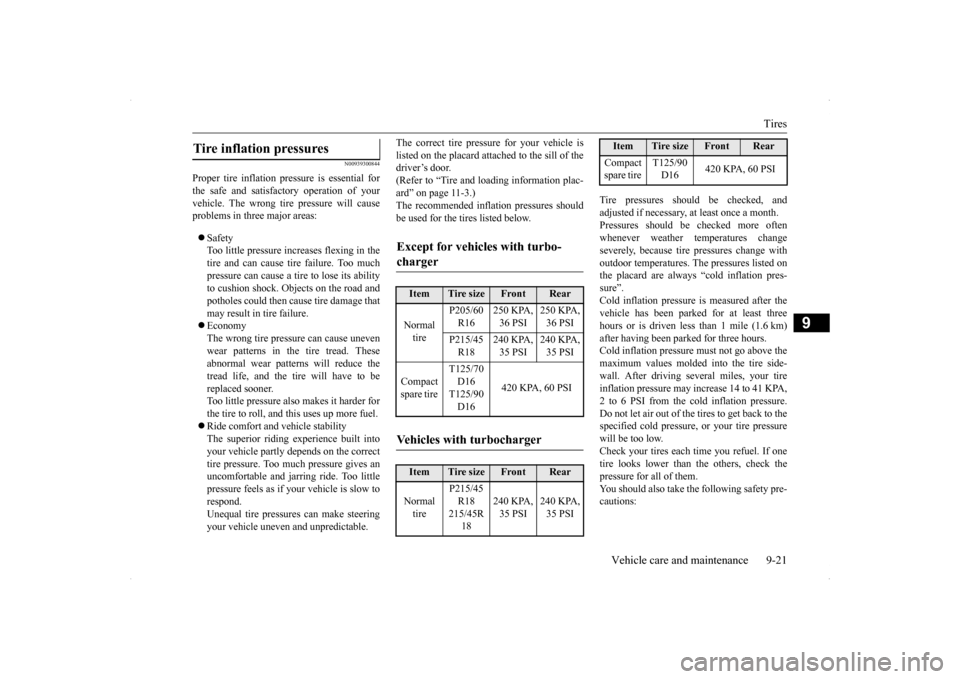
The correct tire pressure for your vehicle is listed on the placard attached to the sill of the driver’s door. (Refer to “Tire and loading information plac-ard” on page 11-3.) The recommended inflation pressures should be used for the tires listed below.
Tire pressures should be checked, and adjusted if necessary, at least once a month. Pressures should be checked more often whenever weather temperatures changeseverely, because tire pressures change with outdoor temperatures. The pressures listed on the placard are always “cold inflation pres-sure”. Cold inflation pressure is measured after the vehicle has been parked for at least threehours or is driven less than 1 mile (1.6 km)after having been parked for three hours. Cold inflation pressure must not go above the maximum values molded into the tire side-wall. After driving several miles, your tire inflation pressure may increase 14 to 41 KPA, 2 to 6 PSI from the cold inflation pressure.Do not let air out of the tires to get back to the specified cold pressure, or your tire pressure will be too low.Check your tires each time you refuel. If one tire looks lower than the others, check the pressure for all of them.You should also take the following safety pre- cautions:
Tire inflation pressures
Except for vehicles with turbo- charger
Item
Tire size
Front
Rear
Normal tire
P205/60 R16
250 KPA, 36 PSI
250 KPA, 36 PSI
P215/45 R18
240 KPA, 35 PSI
240 KPA, 35 PSI
Compact spare tire
T125/70 D16 T125/90D16
420 KPA, 60 PSI
Vehicles with turbocharger
Item
Tire size
Front
Rear
Normal tire
P215/45 R18215/45R
18
240 KPA, 35 PSI
240 KPA, 35 PSI
Compact spare tire
T125/90 D16
420 KPA, 60 PSI
Item
Tire size
Front
Rear
Page 386 of 434
General maintenance
Vehicle care and maintenance 9-27
9
there are other parts which do not usually need regular maintenance. But, if any of these parts stops working prop- erly, your vehicle performance could suffer.Have these items checked if you notice a problem with them. See your authorized Mitsubishi Motors dealer for assistance, if you have any questions.
N00941600033
Good brakes are essen
tial to safe driving.
Check the brake pads and brake linings for wear and check the rear wheel cylinders for leaks. For good braking performance, replacethe brake pads with the
same type pads as the
originals.
N00941700047
Brake hoses and tubing should be checkedfor:
Severe surface cracking, scuffing or worn spots. If the fabric casing of the hose is showing through any cracks or worn spots in the rubber hose cover, the hose shouldbe replaced. The brakes can fail if the hose wears through. Improper installation may cause twisting, or wheel, tire or chassis interference.
N00941800077
Check the following parts for damage andgrease leaks: Ball joint boots of the front suspension and steering linkage Bellows on both ends of the drive shaft
N00942200108
The best way to keep carbon monoxide gas from entering inside your vehicle is to have the engine exhaust system properly serviced.
Have a competent mechanic inspect the com- plete exhaust system and nearby body areas for broken, damaged, deteriorated, or mispo- sitioned parts if you notice any of the follow-ing: A change in the sound of the exhaust sys- tem The smell of exhaust fumes inside the vehicle The underside or rear of the vehicle is damaged
Also check the exhaust system each time the vehicle is raised for lubrication, oil changes,or required service. Any open seams or loose connections could let dangerous exhaust fumes seep into the luggage compartment andpassenger compartments. Check for holes or exhaust gas leaks caused by corrosion or damage. Check the joints and connections for looseness or exhaust gas leaks. Check the rubber hangers and brackets for damage.
Disc brake pads, rear drum brake linings and rear wheel cylinders Brake hoses
Ball joint, steering linkage seals and drive shaft boots Exhaust system
WA R N I N G Carbon monoxide gas from your vehicle’s exhaust is poisonous. Breathing these fumes can cause unconsciousness or death.
Check for any of the following conditions:
Page 398 of 434
Replacement of light bulbs
Vehicle care and maintenance 9-39
9
N00943200121
The alignment of the headlights should be checked by an authorized Mitsubishi Motorsdealer or a repair facility of your choice.
N00917300512
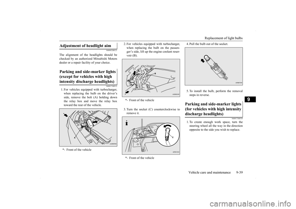
1. For vehicles equipped with turbocharger, when replacing the bulb on the driver’s side, remove the bolt (A) holding downthe relay box and move the relay box toward the rear of the vehicle.
2. For vehicles equipped with turbocharger, when replacing the bulb on the passen- ger’s side, lift up the engine coolant reser- voir (B). 3. Turn the socket (C) counterclockwise to remove it.
4. Pull the bulb out of the socket. 5. To install the bulb, perform the removal steps in reverse.
N00917300538
1. To create enough work space, turn the steering wheel all the way in the direction opposite to the side you wish to replace.
Adjustment of headlight aim Parking and side-marker lights (except for vehicles with high intensity discharge headlights) * - Front of the vehicle
*- Front of the vehicle * - Front of the vehicle
Parking and side-marker lights (for vehicles with high intensity discharge headlights)