audio MITSUBISHI LANCER 2014 8.G Owners Manual
[x] Cancel search | Manufacturer: MITSUBISHI, Model Year: 2014, Model line: LANCER, Model: MITSUBISHI LANCER 2014 8.GPages: 434, PDF Size: 57.5 MB
Page 3 of 434
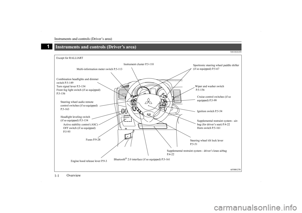
Instruments and controls (Driver’s area) 1-1
1
Overview
N00100202498
Instruments and controls (Driver’s area) Except for RALLIART
Instrument cluster P.5-110
Sportronic steering wheel paddle shifter (if so equipped) P.5-67
Multi-information meter switch P.5-113
Combination headlights and dimmer switch P.5-149 Turn signal lever P.5-154Front fog light switch (if so equipped) P.5-156
Wiper and washer switch P.5-156 Cruise control switches (if so equipped) P.5-99
Steering wheel audio remote control switches (if so equipped) P.5-163
Ignition switch P.5-54
Headlight leveling switch (if so equipped) P.5-154
Supplemental restraint system - air- bag (for driver’s seat) P.4-22 Horn switch P.5-161
Active stability control (ASC) OFF switch (if so equipped) P.5-95
Fuses P.9-28
Steering wheel tilt lock lever P.5-51
Supplemental restraint syst
em - driver’s knee airbag
P.4-22
Bluetooth
® 2.0 interface (if so equipped) P.5-161
Engine hood rele
ase lever P.9-3
Page 4 of 434
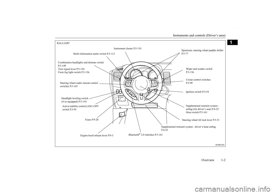
Instruments and controls (Driver’s area)
Overview 1-2
1
RALLIART
Instrument cluster P.5-110
Sportronic steering wheel paddle shifter P.5-77
Multi-information meter switch P.5-113
Combination headlight
s and dimmer switch
P.5-149 Turn signal lever P.5-154 Front fog light switch P.5-156
Wiper and washer switch P.5-156 Cruise control switches P.5-99
Steering wheel audio remote control switches P.5-163
Ignition switch P.5-54
Headlight leveling switch (if so equipped) P.5-154
Supplemental restraint system - airbag (for driver’s seat) P.4-22Horn switch P.5-161
Active stability control (ASC) OFF switch P.5-95
Steering wheel tilt lock lever P.5-51
Fuses P.9-28
Supplemental restraint system
- driver’s knee airbag
P.4-22
Bluetooth
® 2.0 interface P.5-161
Engine hood release lever P.9-3
Page 7 of 434
Center panel 1-5 Overview
1
N00100701207
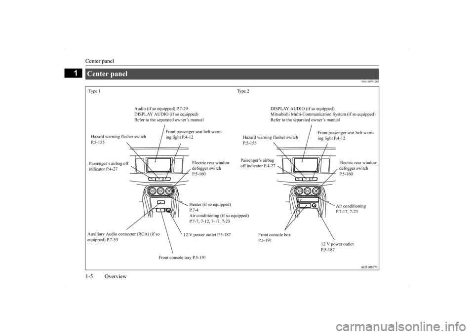
Center panel Type 1 Type 2
Audio (if so equipped) P.7-29 DISPLAY AUDIO (if so equipped) Refer to the separated owner’s manual
DISPLAY AUDIO (if so equipped) Mitsubishi Multi-Communication
System (if so equipped)
Refer to the separated owner’s manual
Hazard warning flasher switch P.5-155
Front passenger seat belt warn- ing light P.4-12
Hazard warning flasher switch P.5-155
Front passenger seat belt warn- ing light P.4-12
Passenger’s airbag off indicator P.4-27
Passenger’s airbag off indicator P.4-27
Electric rear window defogger switch P.5-160
Electric rear window defogger switch P.5-160
Heater (if so equipped) P.7-4 Air conditioning (if so equipped)P.7-7, 7-12, 7-17, 7-23
Air conditioning P.7-17, 7-23
12 V power outlet P.5-187
Auxiliary Audio conne
cter (RCA) (if so
equipped) P.7-53
Front console box P.5-191
12 V power outlet P.5-187
Front console tray P.5-191
Page 28 of 434
Mitsubishi Motors genuine parts
General information 3-7
3
accessory which may involve modification of the electrical or fuel systems.
N00301400105
Mitsubishi Motors Genuine Parts are designed and manufactured to meet high stan- dards of performance, and are recommendedfor all of your maintenance needs. Also avail- able from your Mitsubi
shi Motors dealer are
a wide variety of accessories to personalizeyour new vehicle. Each Mitsubishi vehicle has a selection of Mitsubishi Motors autho- rized accessories to choose from to tailor yournew vehicle to your own personal preference. Your Mitsubishi Motors dealer’s Parts Man- ager has information on various audio sys-tems, protection items, as well as interior and exterior accessories available for your spe- cific model.
N00300100017
Certain components of this vehicle, such asairbag modules, seat belt pretensioners, andbutton cell batteries, may contain perchlorate materials. Special handling may apply. For additionalinformation, see www.dtsc.ca.gov/hazardous- waste/perchlorate.
CAUTION Please consult an authorized Mitsubishi Motors dealer concerning any such acces- sory fitment or modification. If the wires interfere with the vehicle body or improper installation methods are used (pro- tective fuses not included, etc.), electronicdevices may be adversely affected, resulting in a fire, vehicle damage, or other accident.
Mitsubishi Motors genuine parts
California Perchlorate Materials Requirements
Page 71 of 434
![MITSUBISHI LANCER 2014 8.G Owners Manual Electronic immobilizer (Anti-theft starting system) 5-4 Features and controls
5
N00509101804
[For vehicles equipped with the Free-hand Advanced Security Transmitter (F.A.S.T.-key)] For information on MITSUBISHI LANCER 2014 8.G Owners Manual Electronic immobilizer (Anti-theft starting system) 5-4 Features and controls
5
N00509101804
[For vehicles equipped with the Free-hand Advanced Security Transmitter (F.A.S.T.-key)] For information on](/img/19/7460/w960_7460-70.png)
Electronic immobilizer (Anti-theft starting system) 5-4 Features and controls
5
N00509101804
[For vehicles equipped with the Free-hand Advanced Security Transmitter (F.A.S.T.-key)] For information on operations for vehicles equipped with the Free-hand Advanced Secu-rity Transmitter (F.A.S.T.-key), refer to “Free-hand Advanced Security Transmitter (F.A.S.T.-key)”: “Electronic immobilizer(Anti-theft starting system)” on page 5-28. [Except for vehicles equipped with the Free- hand Advanced Security Transmitter (F.A.S.T.-key)] The electronic immobilizer is designed to sig-nificantly reduce the possibility of vehicle theft. The purpose of the system is to immo- bilize the vehicle if an invalid start isattempted. A valid start attempt can only be achieved (subject to certain conditions) using a key “registered” to the immobilizer system.All of the keys provided with your new vehi- cle have been programmed to the vehicle’s electronics.
1- Free-hand Advanced Security Transmit-
ter (F.A.S.T.-key) (with electronic immo
bilizer and keyless
entry system function)
2- Emergency key 3- Key number plate
NOTE
The key is a precision electronic device with a built-in signal transmitter. Please observethe following in order to prevent damage. • Do not leave where it may be exposed to heat caused by direct sunlight, such as on top of the dashboard. • Do not take the remote control transmitter apart. • Do not excessively bend the key or subject it to strong impacts. • Keep the remote control transmitter dry. • Keep away from magnetic objects such as key holders.
• Keep away from devices that produce mag- netism, such as audio systems, computers and televisions. • Keep away from devices that emit strong electromagnetic waves, such as cellular phones, wireless devices and high fre- quency equipment (including medicaldevices). • Do not clean with ultrasonic cleaners.• Do not leave the key where it may be exposed to high temperature or high humid-ity.
If you lose your key, to prevent the theft of the vehicle immediately contact an autho- rized Mitsubishi Motors dealer. If you notify an authorized MitsubishiMotors dealer of the key number, they can make a new key. The key number is stamped on the key number plate. Keep the key num-ber plate in a safe place separate from the key itself. No keys other than those registered in advance can be used to start the engine. Refer to “Electronic immobilizer (Anti-theftstarting system)” on page 5-4. Refer to “Free-hand Advanced Security Transmitter (F.A.S.T.-key)”: “Electronic immobilizer (Anti-theft starting system)” on page 5-28.NOTE
Electronic immobilizer (Anti-theft starting system)
Page 110 of 434
Theft-alarm system
Features and controls 5-43
5
provides both audible and visual alarm sig- nals.
N00510301183
Park the vehicle and st
op the engine. Arm the
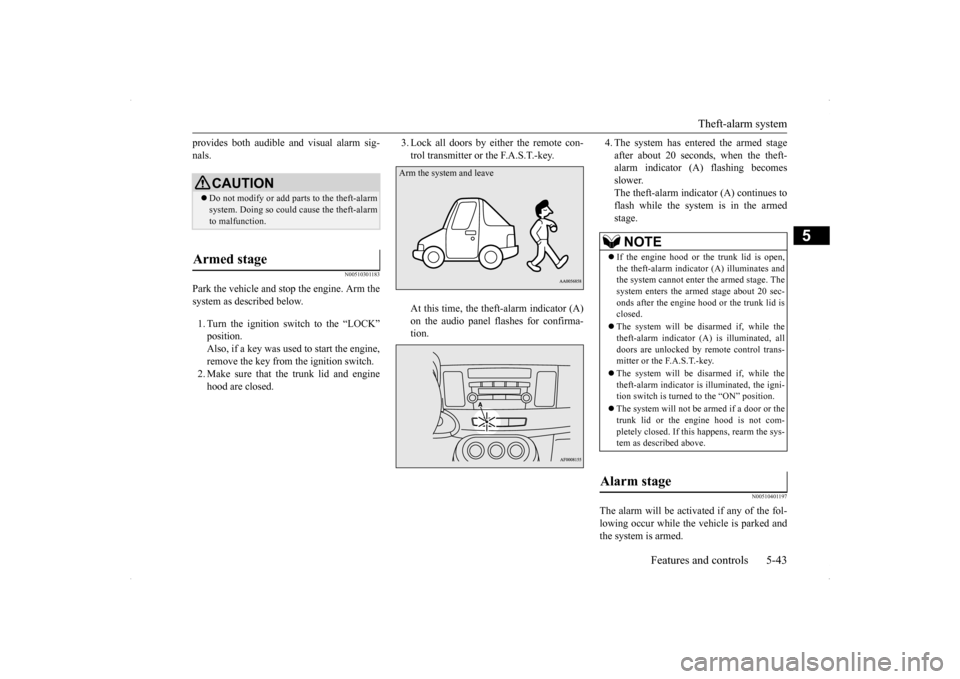
system as described below. 1. Turn the ignition switch to the “LOCK” position. Also, if a key was used to start the engine,remove the key from the ignition switch. 2. Make sure that the trunk lid and engine hood are closed.
3. Lock all doors by either the remote con- trol transmitter or the F.A.S.T.-key. At this time, the theft-alarm indicator (A) on the audio panel flashes for confirma- tion.
4. The system has entered the armed stage after about 20 seconds, when the theft- alarm indicator (A) flashing becomes slower.The theft-alarm indicator (A) continues to flash while the system is in the armed stage.
N00510401197
The alarm will be activated if any of the fol-lowing occur while the vehicle is parked andthe system is armed.
CAUTION Do not modify or add parts to the theft-alarm system. Doing so could cause the theft-alarm to malfunction.
Armed stage
Arm the system and leave
NOTE
If the engine hood or the trunk lid is open, the theft-alarm indicator (A) illuminates and the system cannot enter
the armed stage. The
system enters the armed stage about 20 sec-onds after the engine hood or the trunk lid is closed. The system will be disarmed if, while the theft-alarm indicator (A) is illuminated, all doors are unlocked by remote control trans-mitter or the F.A.S.T.-key. The system will be disarmed if, while the theft-alarm indicator is illuminated, the igni- tion switch is turned to the “ON” position. The system will not be
armed if a door or the
trunk lid or the engine hood is not com- pletely closed. If this happens, rearm the sys-tem as described above.
Alarm stage
Page 122 of 434
Ignition switch
Features and controls 5-55
5
Engages the starter. After the engine starts, release the key and it will return automati-cally to the “ON” position.
N00539601097
After about 30 minutes has elapsed with theignition switch in the “ACC” position, the function automatically cuts out the power for the audio system and other electric devicesthat can be operated with that position. When the ignition switch is turned from the “ACC” position, the power is supplied againto those devices.
N00550900184
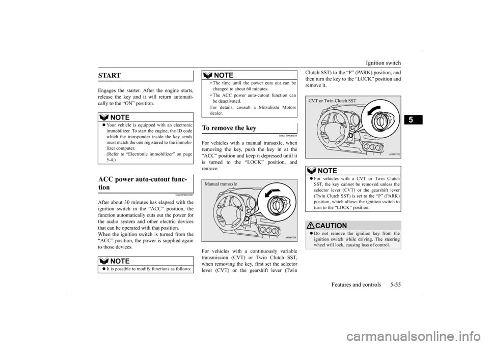
For vehicles with a manual transaxle, whenremoving the key, push the key in at the“ACC” position and keep it depressed until it is turned to the “LOCK” position, and remove. For vehicles with a continuously variable transmission (CVT) or Twin Clutch SST,when removing the key, first set the selector lever (CVT) or the gearshift lever (Twin
Clutch SST) to the “P
” (PARK) position, and
then turn the key to the “LOCK” position and remove it.
START
NOTE
Your vehicle is equipped with an electronic immobilizer. To start the engine, the ID code which the transponder inside the key sendsmust match the one registered to the immobi- lizer computer. (Refer to “Electronic immobilizer” on page5-4.)
ACC power auto-cutout func- tion
NOTE
It is possible to modify functions as follows:
• The time until the power cuts out can be changed to about 60 minutes. • The ACC power auto-cutout function can be deactivated. For details, consult a Mitsubishi Motors dealer.
To remove the key
NOTE
Manual transaxle
NOTE
For vehicles with a CVT or Twin Clutch SST, the key cannot be removed unless the selector lever (CVT) or the gearshift lever(Twin Clutch SST) is set to the “P” (PARK) position, which allows the ignition switch to turn to the “LOCK” position.CAUTION Do not remove the ignition key from the ignition switch while driving. The steering wheel will lock, causing loss of control.CVT or Twin Clutch SST
Page 175 of 434
Rear-view camera (if so equipped) 5-108 Features and controls
5
N00532900179
If new wheels with new tire inflation pressure sensors are installed, their ID codes must be programmed into the tire pressure monitoring system. Have tire and wheel replacement per-formed by an authorized Mitsubishi Motors dealer to avoid the risk of damaging the tire inflation pressure sensors. If the wheelreplacement is not done by an authorizedMitsubishi Motors dealer, it is not covered by your warranty.
N00533001259
Your tire pressure monitoring system oper-ates on a radio frequency subject to Federal Communications Commission (FCC) Rules(For vehicles sold in U.S.A.) and Industry Canada Rules (For vehicles sold in Canada). This device complies with Part 15 of FCCRules and Industry Canada licence-exempt RSS standard(s).
Operation is subject to the following two con- ditions. This device may not cause harmful inter- ference. This device must accept any interference received, including interference that may cause undesired operation.
N00546201154
When the gearshift lever or the selector leveris in the “R” (REVERSE) position with the ignition switch in the “ON” position, the rear-view image will be displayed on the screen of the Mitsubishi Multi-Communication Sys- tem or the DISPLAY AUDIO in the centerpanel. When the gearshift lever or the selector lever is shifted out of the “R” (REVERSE) posi-tion, the rear-view image will go off.
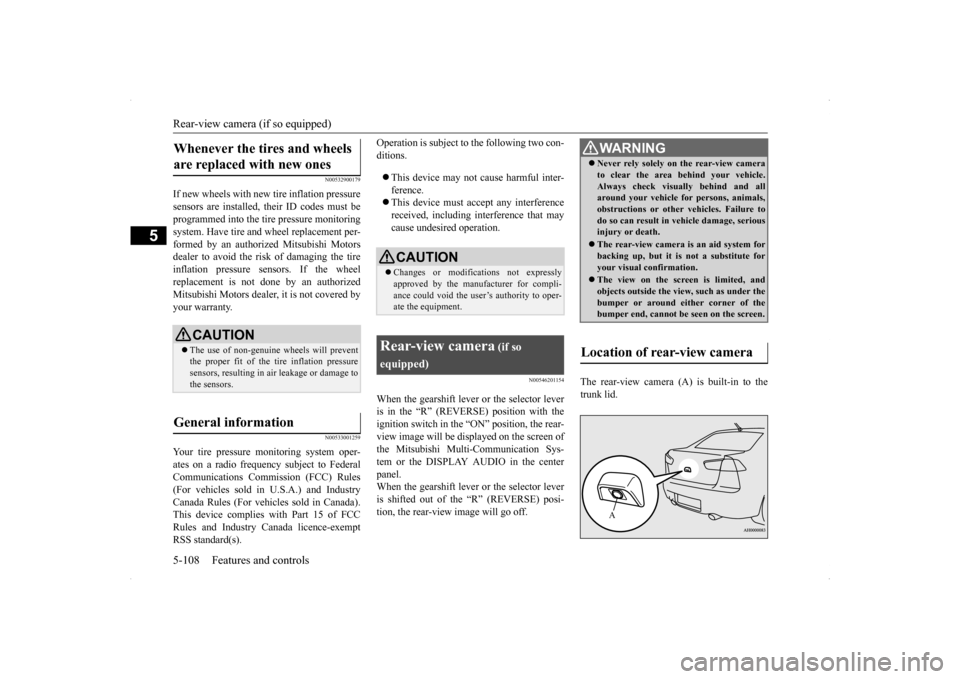
The rear-view camera (A) is built-in to the trunk lid.
Whenever the tires and wheels are replaced with new ones
CAUTION The use of non-genuine wheels will prevent the proper fit of the tire inflation pressuresensors, resulting in air leakage or damage to the sensors.
General information
CAUTION Changes or modifications not expressly approved by the manufacturer for compli- ance could void the user’s authority to oper- ate the equipment.
Rear-view camera
(if so
equipped)
WA R N I N G Never rely solely on the rear-view camera to clear the area behind your vehicle. Always check visually behind and all around your vehicle for persons, animals, obstructions or other vehicles. Failure todo so can result in vehicle damage, serious injury or death. The rear-view camera is an aid system for backing up, but it is not a substitute for your visual confirmation. The view on the screen is limited, and objects outside the vi
ew, such as under the
bumper or around either corner of the bumper end, cannot be seen on the screen.
Location of rear-view camera
A
Page 228 of 434
Horn switch
Features and controls 5-161
5
N00523800156
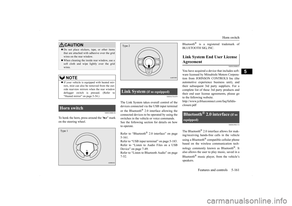
To honk the horn, press around the “ ” mark on the steering wheel.
N00563701079
The Link System takes overall control of thedevices connected via the USB input terminal or the Bluetooth
® 2.0 interface allowing the
connected devices to be operated by using theswitches in the vehicle or voice commands.See the following section for details on how to operate. Refer to “Bluetooth
® 2.0 interface” on page
5-161.Refer to “USB input terminal” on page 5-183. Refer to “Listen to Audio Files on a USB Device” on page 7-49.Refer to “Listen to Bluetooth Audio” on page 7-52.
Bluetooth
® is a registered trademark of
BLUETOOTH SIG, INC.
N00563800015
You have acquired a device that includes soft- ware licensed by Mitsubishi Motors Corpora- tion from JOHNSON CONTROLS Inc (theautomotive experien
ce business unit), and
their subsequent 3rd party suppliers. For a complete list of these 3rd party products and their end user license agreements, please goto the following website. http://www.jciblueconnect.com/faq/fulldis- closure.pdf
N00563901172
The Bluetooth
® 2.0 interface allows for mak-
ing/receiving hands-free calls in the vehicle using a Bluetooth
® compatible cellular phone
based on the wireless communication tech- nology commonly known as Bluetooth
®. It
also allows the user to
play music, saved in a
Bluetooth
® music player, from the vehicle’s
speakers.
Do not place stickers, tape, or other items that are attached with adhesive over the grid wires on the rear window. When cleaning the inside rear window, use a soft cloth and wipe lightly over the grid wires.NOTE
If your vehicle is equipped with heated mir- rors, mist can also be removed from the out-side rearview mirrors when the rear window defogger switch is pressed. (Refer to “Heated mirror” on page 5-54.)
Horn switch
CAUTION
Type 1
Link System
(if so equipped)
Type 2
Link System End User License Agreement
Bluetooth
® 2.0 interface
(if so
equipped)
Page 229 of 434
Bluetooth® 2.0 interface (if so equipped) 5-162 Features and controls
5
The system is equipped with a voice recogni- tion function, which allows you to make hands-free calls by simple switch operations and voice command operations using adefined voice tree. The Bluetooth
® 2.0 interface can be used
when the ignition switch is in the “ON” or “ACC” position. Before you can use the Bluetooth
® 2.0 inter-
face, you must pair the Bluetooth
® device
and Bluetooth
® 2.0 interface. Refer to “Con-
necting the Bluetooth
® 2.0 interface and
Bluetooth
® device” on page 5-169.
Bluetooth
® is a registered trademark of
BLUETOOTH SIG, INC.
Steering control switch and microphone
P.5-163Voice recognition function
P.5-165
Useful voice commands
P.5-165
Speaker enrollment function
P.5-167
Connecting the Bluetooth
® 2.0 interface and
the Bluetooth
® device
P.5-169
Operating a music player connected via Blue- tooth
® P.5-173
How to make or receive hands-free calls
P.5-173 Phonebook function
P.5-176
WA R N I N GAlthough the Bluetooth
® 2.0 interface
allows you to make hands-free calls, if you choose to use the cellular phone whiledriving, you must not allow yourself to be distracted from the safe operation of your vehicle. Anything, including cellularphone usage, that di
stracts you from the
safe operation of your vehicle increases your risk of an accident. Refer to and comply with all state and local laws in your area regarding cellularphone usage while driving.
NOTE
If the ignition switch is left in the “ACC” position, the accessory power will automati- cally turn off after a
certain period of time
and you will no longer be able to use the Bluetooth
® 2.0 interface. The accessory
power comes on again if the ignition switch is turned from the “ACC” position. Refer to “ACC power auto-cutout function” on page5-55. The Bluetooth
® 2.0 interface cannot be used
if the Bluetooth
® device has a dead battery
or the device power is turned off. Hands-free calls will not be possible if your phone does not have service available. Some Bluetooth
® devices are not compatible
with the Bluetooth
® 2.0 interface.
You can confirm the Link System software version by pressing the HANG-UP button 3 times (press and hold 2 times and then press briefly) within 10 seconds.
For detail of the Bluetooth
® 2.0 interface,
refer to the following web site:[For vehicles sold in U.S.A.] You can see to access the MITSUBISHI MOTORS NORTH AMERICA web site.[For vehicles sold in Canada and Mexico] You can see to access via the MITSUBISHI MOTORS web site.Please read and agree the “Warning about Links to the Web Site
s of Other Companies”
because it connects other than MITSUBISHIMOTORS web site. http://www.mitsubishi-motors.com/en/prod- ucts/index.html Software updates by cellular phone/digital audio device manufacturers maychange/alter device connectivity.NOTE