relay MITSUBISHI LANCER EVOLUTION 2007 Service Owner's Manual
[x] Cancel search | Manufacturer: MITSUBISHI, Model Year: 2007, Model line: LANCER EVOLUTION, Model: MITSUBISHI LANCER EVOLUTION 2007Pages: 1449, PDF Size: 56.82 MB
Page 168 of 1449

CIRCUIT DIAGRAMSB-70
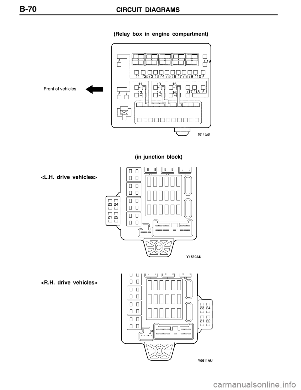
(Relay box in engine compartment)
Front of vehicles
(in junction block)
1234
1213
1415 56 7 8
1617 1819
910
11
21
2324
22
21
2324
22 25
Page 169 of 1449

CIRCUIT DIAGRAMSB-71
MULTI-PURPOSE FUSE (In junction block)
Power supply
circuitNo.Rated
capacity (A)Identification
colourCircuit
Ignition
switch
IG1110RedIgnition coil
switch
27.5BrownColumn switch, combination meter, ETACS-ECU,
SRS-ECU, vehicle speed sensor and ACD mode
changeover switch
37.5BrownETACS-ECU and SRS-ECU
4---
IG257.5BrownA/C compressor relay, A/C-ECU, blower relay,
condenser fan relay, defogger relay, front-ECU,
4WD-ECU, steering wheel sensor and inter cooler
water splay relay
Multi-purpose fuse
No. 20 (Defogger
relay)6---
Ignition
switch
ACC720YellowFront-ECU and windshield wiper motor
switch
IG187.5BrownEngine-ECU and fuel pump relay (1) and fuel pump
relay (2)
ACC915BlueCigarette lighter
10---
117.5BrownA/C-ECU and remote controlled mirror switch
IG2127.5BrownABS-ECU, G-sensor (longitudinal) and G-sensor
(lateral)
ACC13---
14---
Fusible link No. 1
Battery/alternator
1515BlueDiagnosis connector
Battery/alternator
1610RedRear fog lamp relay
1710RedETACS-ECU
18---
1930GreenBlower motor and resistor
2030GreenDefogger
Page 171 of 1449

CIRCUIT DIAGRAMSB-73
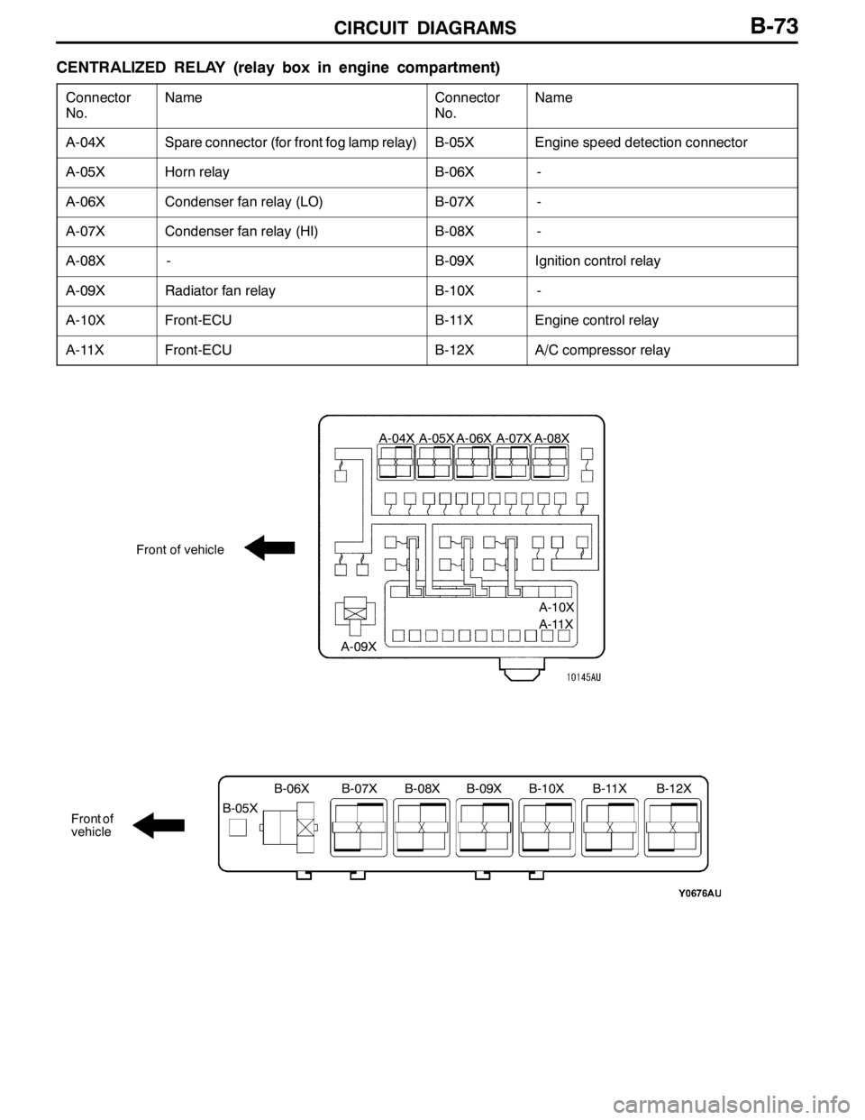
CENTRALIZED RELAY (relay box in engine compartment)
Connector
No.NameConnector
No.Name
A-04XSpare connector (for front fog lamp relay)B-05XEngine speed detection connector
A-05XHorn relayB-06X-
A-06XCondenser fan relay (LO)B-07X-
A-07XCondenser fan relay (HI)B-08X-
A-08X-B-09XIgnition control relay
A-09XRadiator fan relayB-10X-
A-10XFront-ECUB-11XEngine control relay
A-11XFront-ECUB-12XA/C compressor relay
Front of vehicle
Front of
vehicle
A-04X A-05X A-06X A-07X A-08X
A-09XA-10X
A-11X
B-05XB-06X B-07X B-08X B-09X B-10X B-11X B-12X
Page 277 of 1449

CIRCUIT DIAGRAMSB-179
HEATER AND MANUAL AIR CONDITIONER (See P.B-174,180.)
OPERATION
DWhen the ignition switch is turned “ON”, the
blower relay is energized. If the blower switch
is turned “ON” (LO, ML, MH, or HI position)
in this condition, the blower is activated through
the circuit via resistor at a speed corresponding
to the blower switch position.TROUBLESHOOTING HINTS
1. Blower motor is energized at one switch position
and not energized at another.
DCheck resistor.
DCheck blower switch.
2. Blower motor is energized only when switch
is positioned in HI.
DCheck resistor.
Page 357 of 1449

INDEX - In order of connector No.C-1
INDEX
In order of connector No.
Connector
No.Parts nameCircuit diagram pageWiring diagram
page
AA-01Side turn signal lamp (RH)B-135,139B-6,8
A-02Side turn signal lamp (LH)B-134,138B-6,8
A-03Wheel speed sensor (Front:LH)B-203,211,217,225,233,243B-6,8
A-04XSpare connector (for front fog lamp
relay)B-73,258B-6,8
A-05XHorn relayB-73,146B-6,8
A-06XCondenser fan relay (LO)B-73,177,183B-6,8
A-07XCondenser fan relay (HI)B-73,177,183B-6,8
A-08XNo connectionB-73B-6,8
A-09XRadiator fan relayB-73,102,176,182B-6,8
A-10XFront-ECUB-73,75,103,104,106,107,110,111,
114,115,124,127,130,131,132,133,
136,140,187,191, 258B-6,8
A-11XFront-ECUB-73,104,106,107,111,115,124,127,
131,133, 136,140,186,187,190,191B-6,8
A-12Front wiring harness (LH) and control
wiring harness combination
A-13Front wiring harness (LH) and control
wiring harness combination
A-16Headlamp (HI:LH)B-103,106B-6,8
A-21Fan controllerB-102,176,182B-7,8
A-23Horn (HI)B-146B-7,8
A-25Horn (LO)B-146B-7,9
A-28Headlamp (HI:RH)B-103,106B-7,9
A-31Spare connector (for front fog lamp)B-258B-7,9
A-34No connection-B-9
A-36Dual pressure switchB-178,184B-7,9
A-37Wheel speed sensor (Front:RH)B-203,211,217,225,233,243B-7,9
A-39Front combination lamp (LH)B-103,106,110,114,130,132,134,138B-7,9
A-40Front combination lamp (RH)B-103,106,111,114,130,132,135,139B-7,9
A-43Front wiring harness (LH) and control
wiring harness combination
A-44Intercooler water spray motorB-256B-7,9
Page 358 of 1449

INDEX - In order of connector No.C-2
Wiring diagram
page Circuit diagram page Parts name Connector
No.
AA-45Condenser fan motorB-177,183B-7,9
A-46Condenser fan motorB-177,183B-7,9
A-47A/C compressorB-178,184B-7,9
A-48Power steering oil pressure switchB-90,98B-7,9
BB-01Windshield wiper motorB-186,190B-10,14
B-02Throttle position sensorB-89,97,215,223,231,241B-10,14
B-03Vehicle speed sensorB-92,100,150,154,197B-10,14
B-04Brake fluid level switchB-157B-10,14
B-05XEngine speed detection connectorB-73,82,83,90,98B-10,14
B-06XNo connectionB-73B-10,14
B-07XNo connectionB-73B-10,14
B-08XNo connectionB-73B-10,14
B-09XIgnition coil relay
connection
B-10XNo connectionB-73B-10,14
B-11XEngine control relayB-73,86,94,252,254B-10,14
B-12XA/C compressor relayB-73,178,184B-10,14
B-14Control wiring harness and battery
wiring harness combinationB-79,84,91,99,157B-10,14
B-18StarterB-79B-11,15
B-19StarterB-79B-11,15
B-20Oil pressure switchB-157B-11,15
B-21AlternatorB-84B-11,15
B-22AlternatorB-84B-11,15
B-23Purge control solenoid valveB-91,99B-11,15
B-24Injector 4B-89,97B-11,15
B-25Injector 3B-89,97B-11,15
B-26Injector 2B-89,97B-11,15
B-27Injector 1B-89,97B-11,15
B-31Air flow sensorB-90,98B-11,15
B-34Oxygen sensorB-88,96B-11,15
B-36Waste gate solenoid valveB-91,99B-11,15
B-37Fuel pressure solenoid valveB-90,98B-11,15
Page 359 of 1449

INDEX - In order of connector No.C-3
Wiring diagram
page Circuit diagram page Parts name Connector
No.
BB-108Back-up lamp switchB-142,143B-12,16
B-110Engine coolant temperature gauge unitB-148,152B-12,16
B-112EGR solenoid valveB-91,99B-12,16
B-114Ignition coil 1B-82,83B-12,16
B-115Idle speed control servoB-88,96B-12,16
B-116Camshaft position sensorB-88,96B-12,16
B-118Engine coolant temperature sensorB-89,97B-12,16
B-119Ignition coil 2B-82,83B-12,16
B-121Crank angle sensorB-88,96B-13,16
B-122Detonation sensorB-89,97B-13,17
B-123ABS-ECUB-198,200,201,202,203,204,205,206,
208,209,210,211,229,232,233,239,
242,243B-13,17
B-138ResistorB-89,97B-13,17
B-139Electric pump relay
B-140Fuel pump relay 3B-93,101B-13,17
B-141Fuel pump resistorB-93,101B-13,17
B-142Secondary air control solenoid valveB-91,99B-13,17
CC-01Combination meterB-84,87,95,103,106,118,122,126,129,
135,139,148,149,152,153,156,157,
198,206,214,222,230,240,248,250,
256, 258B-18,24
C-02Combination meterB-110,115,118,122,126,129,135,139,
148,149,152,153,156,157,198,206,
248, 250,256,258B-18,24
C-03Hazard warning switchB-136,140B-18,24
C-04ClockB-194B-18,24
C-05J/C (1)B-56,62,93,101,104,107,111,112,115,
116,118,122,124,125,127,128,131,
133,136,137,140,141,148,152,153,
156,158,164,170,172,175,181,185,
187,191,194,195,196,197,212,214,
220,222,228,230,238,240,257B-18,24
C-08J/C (3)B-58,64,95,104,105,107,108,112,113,
116,117,119,123,124,125,126,127,
128,129,131,133,136,137,140,141,
149,153,159,164,165,171,172,173,
175,180,181,185,187,188,189,191,
193,194,195,202,210,214,218,222,
226,227,230,236,240,246,247,253,
255,257,258B-18,24
Page 363 of 1449

INDEX - In order of connector No.C-7
Wiring diagram
page Circuit diagram page Parts name Connector
No.
CC-207Air bag module (squib)
C-208Instrument panel wiring harness and
J/B combinationB-54,55,126,129,256B-22,28
C-209Instrument panel wiring harness and
J/B combinationB-54,55,87,95,104,105,107,108,110,
111,112,115,116,118,122,125,128,134,
136,137,138,139,140,141,142,143,
149,153,158,164,170,172,174,180,
186,187,188,189,190,191,189,198,
202,206,210,218,222,226,236,240,
246,256B-22,28
C-210Instrument panel wiring harness and
J/B combinationB-54,55,76,77,78,82,83,84,87,95,104,
107,111,112,115,116,118,122,125,128,
136,137,140,141,142,143,149,153,
157,158,159,164,165,170,172,174,
180,185,186,187,190,191,192,193,
195,198,200,202,206,208,210,212,
213,214,218,220,221,222,226,228,
229,230,236,238,239,240,246,248,
250, 256B-22,28
C-211Instrument panel wiring harness and
J/B combinationB-54,55,78,92,100,105,108,113,117,
119,123,125,128,137,141,150,154,
158,164,170,172,174,180,185,188,
189,204,205,219,227,237,247,248,
250,252,254B-22,28
C-213Instrument panel wiring harness and
J/B combinationB-54,55,78,82,83,84,87,92,95,100,
104,105,107,108,110,112,113,115,
116,117,119,120,121,123,125,126,
128,129,135,136,137,139,140,141,
149,150,153,154,157,158,164,170,
171,172,173,174,180,185,187,188,
189,191,192,193,195,198,200,204,
205,206,208,212,213,214,219,220,
221,222,227,228,229,230,237,238,
239,240,247,248, 250,252,254,256B-22,28
C-214Defogger relayB-54,55,78,185B-23,29
C-215Blower relayB-54,55,174,180B-23,29
C-216Floor wiring harness (LH) and J/B
combination
158,171,185B-23
C-217Floor wiring harness (RH) and J/B
combination
164, 173,185B-29
C-218Roof wiring harness (RH) and J/B
combinationB-54,55,118,119,122,123B-23,29
C-219Rear fog lamp relayB-54,55,126,129B-23,29
C-220No connectionB-54,55B-23,29
C-221Fuel pump relay 2B-54,55,87,95B-23,29
C-222Intercooler water spray relayB-54,55,256B-23,29
Page 364 of 1449

INDEX - In order of connector No.C-8
Wiring diagram
page Circuit diagram page Parts name Connector
No.
CC-223Fuel pump relay 1B-54,55,87,95B-23,29
C-224Power window relayB-54,55,158,159,165B-23,29
C-225No connectionB-54,55,78B-23,29
C-226ETACS-ECUB-54,55,105,108,112,113,116,117,118,
119,120,121,122,123,125,126,128,
129,134,136,137,138,140,141,158,
164,165, 170,171,172,173,188,189B-23,29
C-227ETACS-ECUB-125,128,170,172B-23,29
C-228ETACS-ECUB-105,108,112,113,116,117,118,119,
122,123,125,126,128,129,136,137,
140,141,158,159,164,165,170,171,
172,173, 188,189,258B-23,29
C-230Steering wheel sensorB-202,210,218,226,236,246B-23,29
DD-01Door switch (Front:RH)B-108,116,120,121,164B-30,32
D-02Floor wiring harness (RH) and rear door
wiring harness (RH) combinationB-160,166,171,173B-30,32
D-03Room lampB-118,122B-30,32
D-04Wheel speed sensor (Rear:RH)
D-05Rear room lampB-118,122B-30,32
D-06Door switch (Rear:RH)B-120,121B-30,32
D-08Door switch (Rear:LH)B-120,121B-30,32
D-09Fuel pump and fuel gauge unit (Main)B-93,101,148,152,156B-30,32
D-10Wheel speed sensor (Rear:LH)
D-12Floor wiring harness (LH) and rear door
wiring harness (LH) combinationB-161,167,171,173B-30,32
D-13Door switch (Front:LH)B-105,112,120,121,158B-30,32
D-15Instrument panel wiring harness and
console wiring harness combinationB-195B-31,32
D-18Cigarette lighterB-195B-31,33
D-19Cigarette lighterB-195B-31,33
D-20Ashtray illumination lampB-195B-31,33
D-21Cigarette lighter illumination lampB-195B-31,33
D-22Oxygen sensor (Rear)B-88,96B-31,33
D-23Parking brake switchB-157,201,209,213,221,232,242B-31,33
D-26Seat belt pretensioner (RH)B-249,251B-31,33
Page 367 of 1449

INDEX - In order of parts nameC-11
INDEX
In order of parts name
Parts nameConnector
No.Circuit diagram pageWiring diagram
page
4WD-ECU
219,220,221,222,223,224,226,227,
228,230,231,232,234,236,237,238,
240,241,242,244, 246,247B-19,25
4WD-ECU
221,224,225,227,228,229,232,234,
235,237,238,239,242,244,245,247B-19,25
AA/C compressorA-47B-178,184B-7,9
A/C compressor relayB-12XB-73,178,184B-10,14
A/C-ECU or heater control unitC-32B-175,181,185B-19,25
ABS-ECUB-123B-198,200,201,202,203,204,205,206,
208,209,210,211,229,232,233,239,
242,243B-13,17
ACD mode changeover switchC-142B-214,222,230,240B-21,27
Air bag module (squib)
Air bag module (squib)
Air flow sensorB-31B-90,98B-11,15
AlternatorB-21B-84B-11,15
AlternatorB-22B-84B-11,15
Ashtray illumination lampD-20B-195B-31,33
BBack-up lamp switchB-108B-142,143B-12,16
Blower motorC-14B-174,180B-18,24
Blower relayC-215B-54,55,174,180B-23,29
Blower switchC-131B-174,180B-21,27
Brake fluid level switchB-04B-157B-10,14
CCamshaft position sensorB-116B-88,96B-12,16
Cigarette lighterD-18B-195B-31,33
Cigarette lighterD-19B-195B-31,33
Cigarette lighter illumination lampD-21B-195B-31,33
ClockC-04B-194B-18,24
Clock spring
Clock spring