diagram MITSUBISHI LANCER EVOLUTION 2007 Service Repair Manual
[x] Cancel search | Manufacturer: MITSUBISHI, Model Year: 2007, Model line: LANCER EVOLUTION, Model: MITSUBISHI LANCER EVOLUTION 2007Pages: 1449, PDF Size: 56.82 MB
Page 1108 of 1449

PARKING BRAKES -General Information/Service Specifications/Lubricants36-2
GENERAL INFORMATION
The parking brake is of a mechanical control type
acting on the rear wheels. A lever is used to apply
the parking brake.
CONSTRUCTION DIAGRAM
Parking brake lever
Parking brake lever
SERVICE SPECIFICATIONS
ItemsStandard valueLimit
Parking brake lever stroke5 - 7 notches-
Rear brake lining thickness mm2.81.0
Rear drum inside diameter mm168.0169.0
LUBRICANTS
ItemsSpecified lubricants
Backing plateMultipurpose grease
Shoe and lining assembly
Adjuster
Page 1117 of 1449

STEERING -General Information37A-3
CONSTRUCTION DIAGRAM
Reservoir tank
Reservoir tank
Steering gear and linkage Return hose
Suction hose
Pressure hoseSteering wheel
Steering column and shaft
Oil pump
assembly
Steering gear
and linkage Return hose
Suction hose
Pressure hoseSteering wheel
Steering column and shaft
Oil pump
assembly
Cooler tube
Cooler tube
Page 1251 of 1449

SRS -Troubleshooting52B-7
SRS SYSTEM CIRCUIT DIAGRAM
Ignition switch (IG1)
J/B
(common fuse)
Combination
Meter
Connector lock switch*
ON
ON OFF
OFF
Driver’s air
bag module
(squib)
Front pas-
senger’s seat
air bag mod-
ule(squib)
Seat belt
pre-tensioner
(L.H.)Clock spring
ONONOFF
OFF
Connector lock switch* Diagnosis connector SRS-ECU
No.3
7.5A No.2
7.5A
OFF
OFF
OFF
OFF
OFF
OFF
OFF
OFFON
ON
ON
ON
ON
ON
ON
ONOFF
ON
ON OFF
C-207
C-204
C-109
D-28
D-26C-22
SRS - ECU connector16
13
7 8
11
12
10
9
30
29
28
2720 Connector lock switch*
Connector lock switch*
Connector lock switch*
Connector lock switch*
Connector lock switch*
NOTE
*:connector engaged:ON
connector disengaged:OFF Seat belt
pre-tensioner
(R.H.)
Page 1274 of 1449

SRS -Troubleshooting52B-30
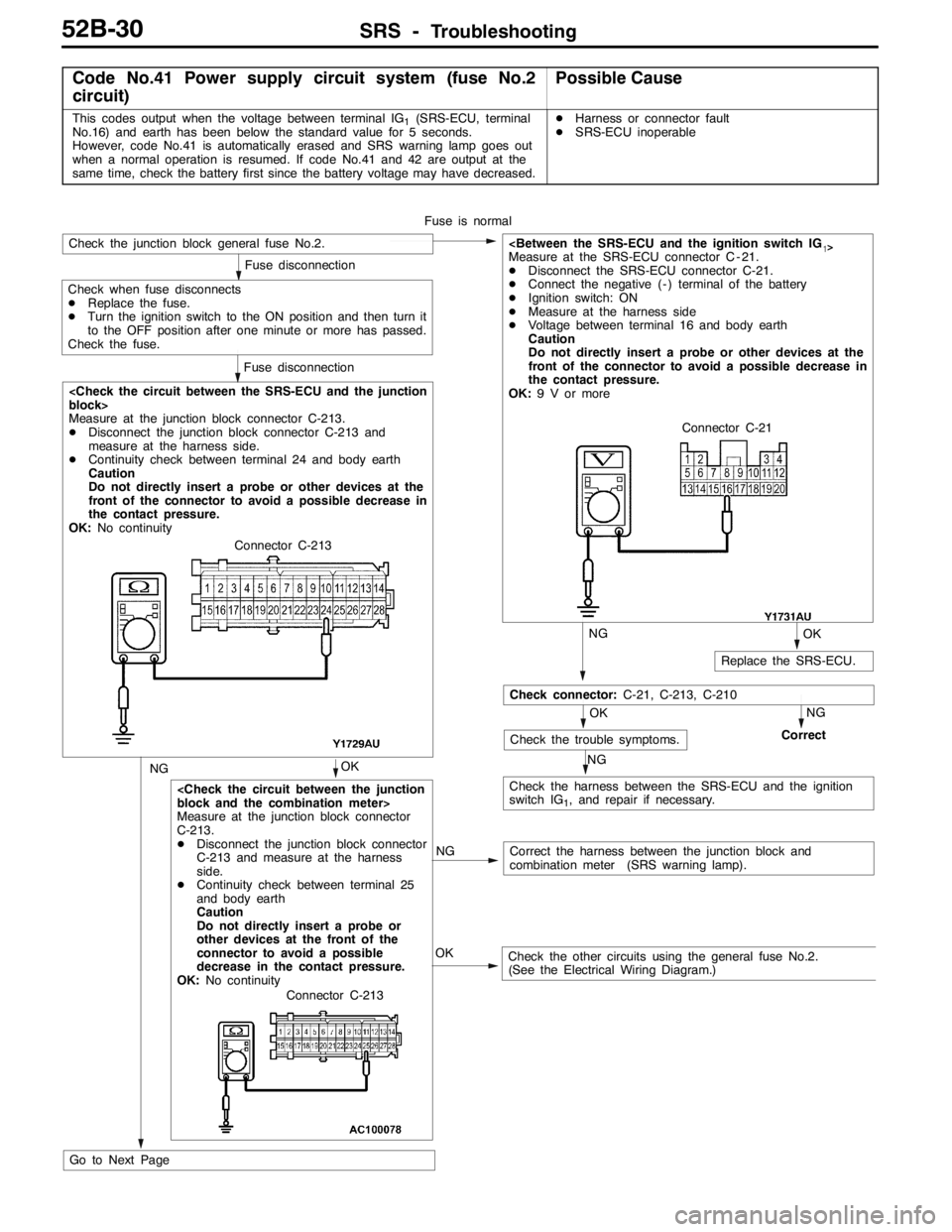
Code No.41 Power supply circuit system (fuse No.2
circuit)Possible Cause
This codes output when the voltage between terminal IG1(SRS-ECU, terminal
No.16) and earth has been below the standard value for 5 seconds.
However, code No.41 is automatically erased and SRS warning lamp goes out
when a normal operation is resumed. If code No.41 and 42 are output at the
same time, check the battery first since the battery voltage may have decreased.DHarness or connector fault
DSRS-ECU inoperable
Measure at the junction block connector
C-213.
DDisconnect the junction block connector
C-213 and measure at the harness
side.
DContinuity check between terminal 25
and body earth
Caution
Do not directly insert a probe or
other devices at the front of the
connector to avoid a possible
decrease in the contact pressure.
OK:No continuity
Measure at the junction block connector C-213.
DDisconnect the junction block connector C-213 and
measure at the harness side.
DContinuity check between terminal 24 and body earth
Caution
Do not directly insert a probe or other devices at the
front of the connector to avoid a possible decrease in
the contact pressure.
OK:No continuity
NGCorrect the harness between the junction block and
combination meter (SRS warning lamp).
NGOK
NGNG
Check the trouble symptoms.Correct
Check the harness between the SRS-ECU and the ignition
switch IG
1, and repair if necessary. Fuse is normal
NG
Fuse disconnection
Check the junction block general fuse No.2.
Fuse disconnection
Check when fuse disconnects
DReplace the fuse.
DTurn the ignition switch to the ON position and then turn it
to the OFF position after one minute or more has passed.
Check the fuse.
OK
OK
Replace the SRS-ECU.
DDisconnect the SRS-ECU connector C-21.
DConnect the negative ( - ) terminal of the battery
DIgnition switch: ON
DMeasure at the harness side
DVoltage between terminal 16 and body earth
Caution
Do not directly insert a probe or other devices at the
front of the connector to avoid a possible decrease in
the contact pressure.
OK:9 V or more
Check the other circuits using the general fuse No.2.
(See the Electrical Wiring Diagram.) OK
Check connector:C-21, C-213, C-210
Go to Next PageConnector C-21
Connector C-213
Connector C-213
Page 1276 of 1449

SRS -Troubleshooting52B-32
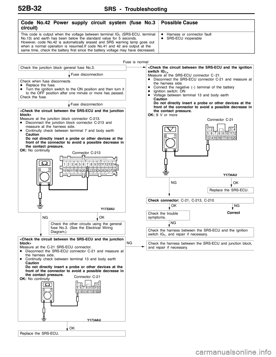
Code No.42 Power supply circuit system (fuse No.3
circuit)Possible Cause
This code is output when the voltage between terminal IG1(SRS-ECU, terminal
No.13) and earth has been below the standard value for 5 seconds.
However, code No.42 is automatically erased and SRS warning lamp goes out
when a normal operation is resumed.If code No.41 and 42 are output at the
same time, check the battery first since the battery voltage may have decreased.DHarness or connector fault
DSRS-ECU inoperable
OK
Check the other circuits using the general
fuse No.3. (See the Electrical Wiring
Diagram.)
NGOK
NG
NG
NG
Check connector:C-21, C-213, C-210
Check the trouble
symptoms.Correct
Check the harness between the SRS-ECU and the ignition
switch IG
1, and repair if necessary.
NG
Fuse disconnection
Fuse disconnection
OK
Replace the SRS-ECU.
1
>Measure at the SRS-ECU connector C - 21.
DDisconnect the SRS-ECU connector C-21 and measure at
the harness side.
DConnect the negative ( - ) terminal of the battery
DIgnition switch: ON
DVoltage between terminal 13 and body earth
Caution
Do not directly insert a probe or other devices at the
front of the connector to avoid a possible decrease in
the contact pressure.
OK:9 V or more
OK
Check the harness between the SRS-ECU and junction block,
and repair if necessary.
Measure at the C-21 SRS-ECU connector.
DDisconnect the SRS-ECU connector C-21 and measure at
the harness side.
DContinuity check between terminal 13 and body earth
Caution
Do not directly insert a probe or other devices at the
front of the connector to avoid a possible decrease in
the contact pressure.
OK:No continuity
Replace the SRS-ECU.Fuse is normal
Check the junction block general fuse No.3.
Check when fuse disconnects
DReplace the fuse.
DTurn the ignition switch to the ON position and then turn it
to the OFF position after one minute or more has passed.
Check the fuse.
Measure at the junction block connector C-213.
DDisconnect the junction block connector C-213 and
measure at the harness side.
DContinuity check between terminal 7 and body earth
Caution
Do not directly insert a probe or other devices at the
front of the connector to avoid a possible decrease in
the contact pressure.
OK:No continuityConnector C-21
Connector C-213
Connector C-21
Page 1437 of 1449

HEATER, AIR CONDITIONER AND VENTILATION-Evaporator, Air Thermo Sensor55-35
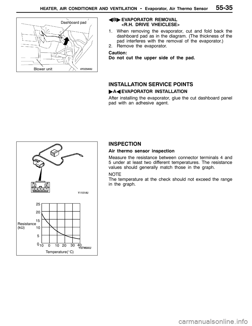
AB"EVAPORATOR REMOVAL
1. When removing the evaporator, cut and fold back the
dashboard pad as in the diagram. (The thickness of the
pad interferes with the removal of the evaporator.)
2. Remove the evaporator.
Caution:
Do not cut the upper side of the pad.
INSTALLATION SERVICE POINTS
"AAEVAPORATOR INSTALLATION
After installing the evaporator, glue the cut dashboard panel
pad with an adhesive agent.
INSPECTION
Air thermo sensor inspection
Measure the resistance between connector terminals 4 and
5 under at least two different temperatures. The resistance
values should generally match those in the graph.
NOTE
The temperature at the check should not exceed the range
in the graph.
Blower unit
Dashboard pad
Resistance
(kΩ)
Temperature(_C) 20
15
10
5
0
-10 0 1040
30
20
25