Body panel MITSUBISHI LANCER EVOLUTION 2007 Service Owner's Guide
[x] Cancel search | Manufacturer: MITSUBISHI, Model Year: 2007, Model line: LANCER EVOLUTION, Model: MITSUBISHI LANCER EVOLUTION 2007Pages: 1449, PDF Size: 56.82 MB
Page 86 of 1449
WIRING AND PIPING DIAGRAM -Wiring and Piping DiagramG-2
WIRING AND PIPING DIAGRAM
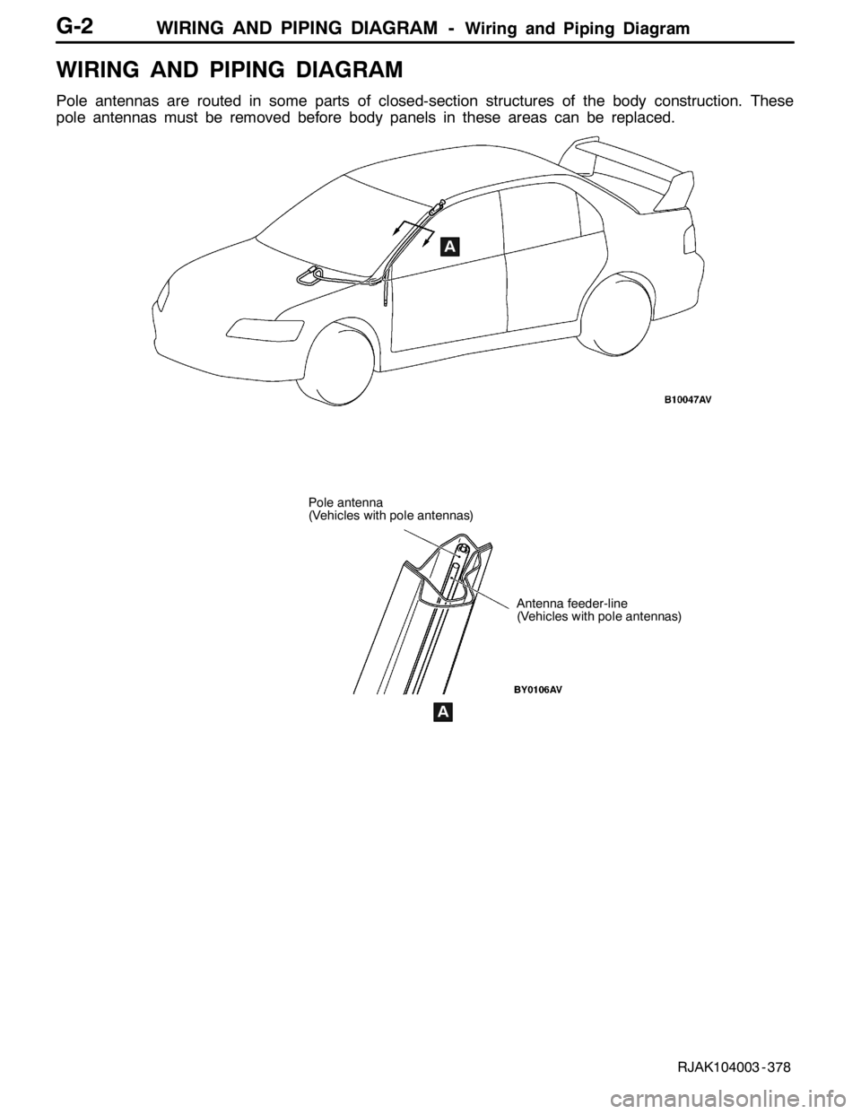
Pole antennas are routed in some parts of closed-section structures of the body construction. These
pole antennas must be removed before body panels in these areas can be replaced.
1
1
Pole antenna
(Vehicles with pole antennas)
A
Antenna feeder-line
(Vehicles with pole antennas)
A
RJAK104003 - 378
Page 1151 of 1449
BODY -Hood42-3
HOOD
REMOVAL AND INSTALLATION
13
23
4 5
9 7
18
62
9.0±2.0 N·m
10
12 13
15
16 17
7
A A
Section A - ASection B - B
B B
1111
10
15
Remarks
and indicate the clip position.
Clip
11
151010
15
18
14
Clip
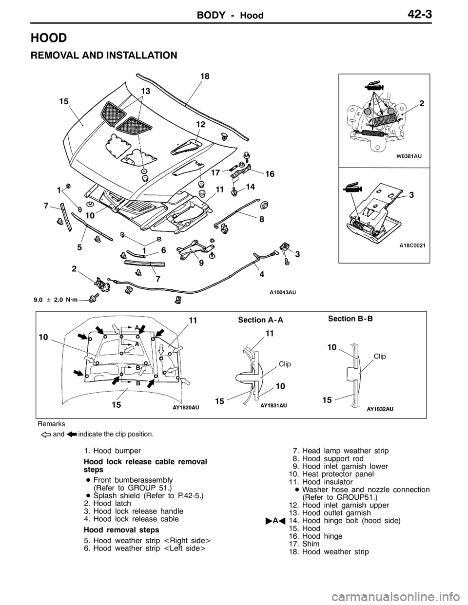
1. Hood bumper
Hood lock release cable removal
steps
DFront bumberassembly
(Refer to GROUP51.)
DSplash shield (Refer to P.42-5.)
2. Hood latch
3. Hood lock release handle
4. Hood lock release cable
Hood removal steps
5. Hood weather strip
6. Hood weather strip
8. Hood support rod
9. Hood inlet garnish lower
10. Heat protector panel
11. Hood insulator
DWasher hose and nozzle connection
(Refer to GROUP51.)
12. Hood inlet garnish upper
13. Hood outlet garnish
"AA14. Hood hinge bolt (hood side)
15. Hood
16. Hood hinge
17. Shim
18. Hood weather strip
Page 1154 of 1449
BODY -Fender42-6
REMOVAL SERVICE POINTS
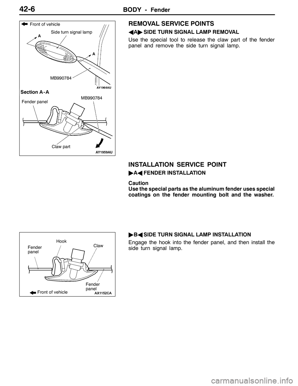
AA"SIDE TURN SIGNAL LAMP REMOVAL
Use the special tool to release the claw part of the fender
panel and remove the side turn signal lamp.
INSTALLATION SERVICE POINT
"AAFENDER INSTALLATION
Caution
Use the special parts as the aluminum fender uses special
coatings on the fender mounting bolt and the washer.
"BASIDE TURN SIGNAL LAMP INSTALLATION
Engage the hook into the fender panel, and then install the
side turn signal lamp.
Claw part
A
Section A - A
A
Front of vehicle
Side turn signal lamp
Fender panel
MB990784
MB990784
Claw Hook
Fender
panel
Fender
panel
Front of vehicle
Page 1155 of 1449

BODY -Fuel Filler Door42-7
FUEL FILLER DOOR
REMOVAL AND INSTALLATION
Pre-removal and Post-installation Operations
DRear Seat Removal and Installation. (Refer to GROUP
52A.)
DFront Scuff Plate (Driver’s Side), Rear Scuff Plate(Driver’s Side), Center Pillar Lower Trim (Driver’s
Side), Quarter Trim (Driver’s Side) Removal and
Installation (Refer to GROUP 52A – Trim.)
5
1
3 4 3
2
5.0±1.0 N·m
Adjustment of clearance around
fuel filler door
Removal steps
1. Fuel filler door panel assembly
2. Clip
3. Fuel filler door hook assembly4. Fuel filler door lock release cable
5. Fuel filler door lock release handle
Page 1175 of 1449

BODY -Doors42-27
DOOR TRIM AND WATERPROOF FILM
REMOVAL AND INSTALLATION
7
91
1011
6 9
9
3
521
2
4 8
4 87 6 5 11
103
Sealant: 3M ATD Part No. 8625 or equivalent
Removal steps
1. Cap
2. Door pull handle
3. Power window switch panel
assembly
AA"4. Door inside handle cover
AB""BA5. Clip
"BA7. Regulator handle
8. Door trim assembly
9. Speaker
10. Power window switch bracket
"AA11. Waterproof film
Page 1176 of 1449
BODY -Doors42-28
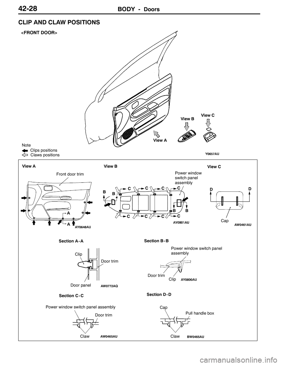
CLIP AND CLAW POSITIONS
Door trim
Section A - A View A
View C
Section C - CSection D - D Section B - B
D Front door trim
Door trim
Clip
Door trim A
AView BView C
Door panel
ClawCapD
Cap
Claw View A
AW0461AU
AW0772AQ
AW0465AU
Power window switch panel
assembly
Power window switch panel assembly
BW0465AU
Note
Claws positions Clips positions
B View B
BC
C
CC
C
CC
C BBPower window
switch panel
assembly
Clip
Pull handle box
Page 1177 of 1449
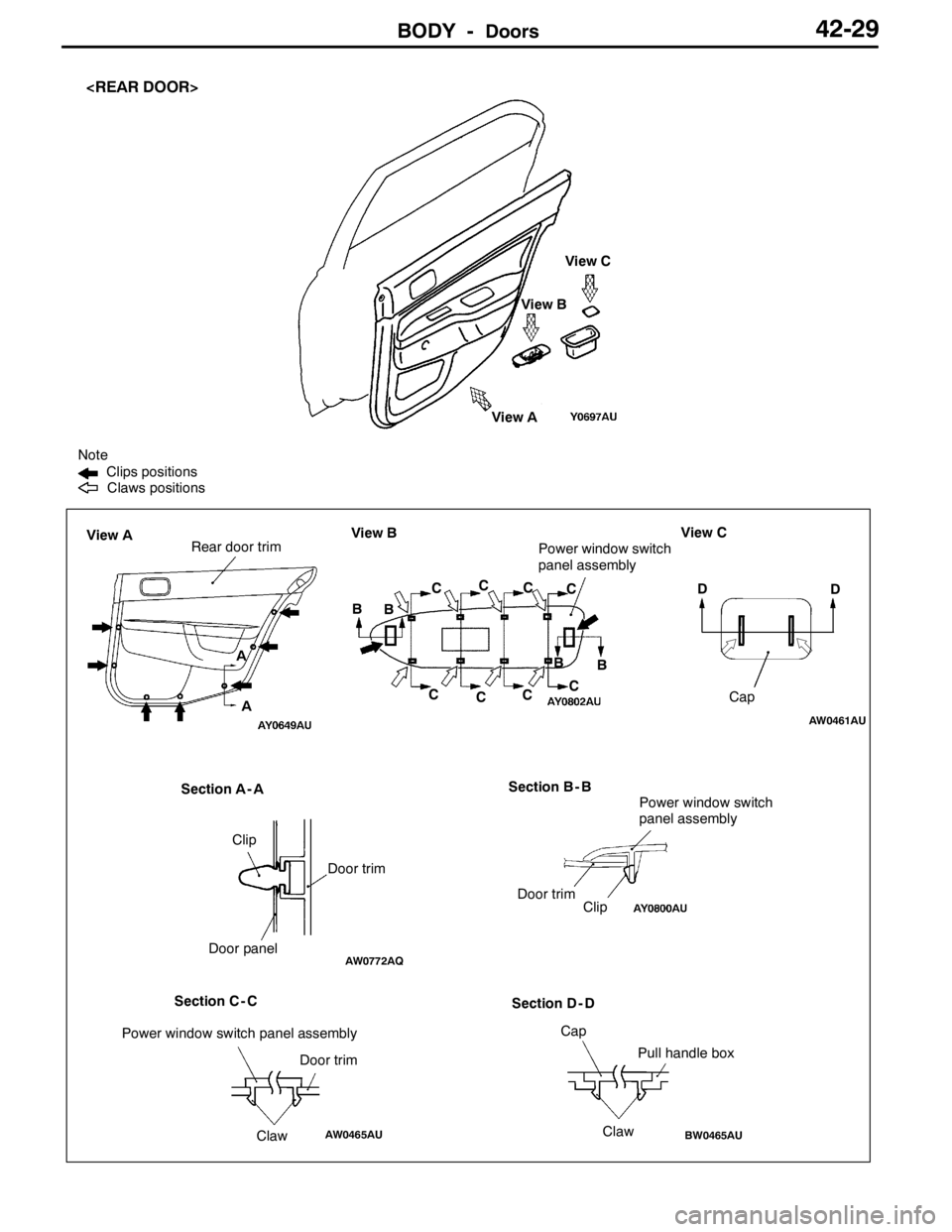
BODY -Doors42-29
B Note
Section A - A View AView B Claws positions Clips positions
Rear door trimView AView B
Door panelDoor trim Clip
D
Cap View C
D
Section C - C
Cap
ClawPull handle box
View C
B
AW0461AU
AW0772AQ
BW0465AU
Section D - D Section B - B
Door trim
Clip C
C
CC
C
C
A
A
C
C B
B Power window switch
panel assembly
Power window switch
panel assembly
ClawDoor trim Power window switch panel assembly
AW0465AU
Page 1181 of 1449
BODY -Doors42-33
REMOVAL SERVICE POINTS
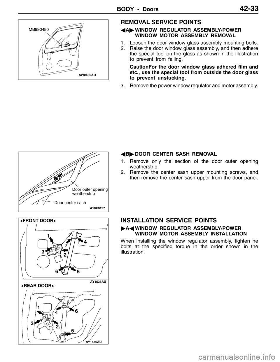
AA"WINDOW REGULATOR ASSEMBLY/POWER
WINDOW MOTOR ASSEMBLY REMOVAL
1. Loosen the door window glass assembly mounting bolts.
2. Raise the door window glass assembly, and then adhere
the special tool on the glass as shown in the illustration
to prevent from falling.
CautionFor the door window glass adhered film and
etc., use the special tool from outside the door glass
to prevent unstucking.
3. Remove the power window regulator and motor assembly.
AB"DOOR CENTER SASH REMOVAL
1. Remove only the section of the door outer opening
weatherstrip
2. Remove the center sash upper mounting screws, and
then remove the center sash upper from the door panel.
INSTALLATION SERVICE POINTS
"AAWINDOW REGULATOR ASSEMBLY/POWER
WINDOW MOTOR ASSEMBLY INSTALLATION
When installing the window regulator assembly, tighten he
bolts at the specified torque in the order shown in the
illustration.
MB990480
Door outer opening
weatherstrip
Door center sash
A18X0127
1
2 4
3
56
1
2
34
5 67
Page 1187 of 1449
BODY -Doors42-39
Sectional view of
clip positionSectional view of
clip position
5
4 3
21
Section A - A
Door
6
A
A
6
BB
Section B - B
Door
23
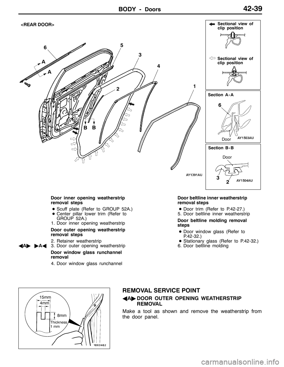
Door inner opening weatherstrip
removal steps
DScuff plate (Refer to GROUP 52A.)
DCenter pillar lower trim (Refer to
GROUP 52A.)
1. Door inner opening weatherstrip
Door outer opening weatherstrip
removal steps
2. Retainer weatherstrip
AA""AA3. Door outer opening weatherstrip
Door window glass runchannel
removal
4. Door window glass runchannelDoor beltline inner weatherstrip
removal steps
DDoor trim (Refer to P.42-27.)
5. Door beltline inner weatherstrip
Door beltline molding removal
steps
DDoor window glass (Refer to
P.42-32.)
DStationary glass (Refer to P.42-32.)
6. Door beltline molding
REMOVAL SERVICE POINT
AA"DOOR OUTER OPENING WEATHERSTRIP
REMOVAL
Make a tool as shown and remove the weatherstrip from
the door panel.15mm
4mm
8mm
Thickness
1mm
Page 1189 of 1449

BODY -Trunk lid42-41
TRUNK LID
REMOVAL AND INSTALLATION
2
34 56
7 89 10
111
12A
A
B
B5 5
99
14Measure of
length mm
15
4 9
12
8.9±1.9 N·m
Section A - A
Section B - B
Trunk lid weatherstrip removal
steps
DRear end trim
GROUP 52A.)
"BA1. Trunk lid weatherstrip
Trunk lid release cable and trunk
lid release handle removal steps
DTrunk rear side trim (Left side)
(Refer to GROUP 52A.)
DRear seat (Refer to GROUP 52A.)
DCenter pillar lower trim (Refer to
GROUP 52A.)
DCowl side trim
DAccelerator pedal stopper
2. Trunk lid release handle
3. Trunk lid release cable
Trunk lid striker removal steps
DRear end trim
GROUP 52A.)4. Trunk lid striker
Trunk lid panel removal steps
5. Trunk lid bumper
6. Trunk lid lock cylinder
7. Trunk lid latch assembly
8. Trunk lid hinge mounting bolt
9. Trunk lid panel assembly
Trunk lid latch assembly removal
7. Trunk lid latch assembly
Trunk lid hinge removal steps
DRear shelf trim
DRear seat (Refer to GROUP 52A.)
9. Trunk lid panel assembly
AA""AA10. Trunk lid torsion bar (Right side)
AA""AA11. Trunk lid torsion bar (Left side)
12. Trunk lid hinge