Body panel MITSUBISHI LANCER EVOLUTION 2007 Service Service Manual
[x] Cancel search | Manufacturer: MITSUBISHI, Model Year: 2007, Model line: LANCER EVOLUTION, Model: MITSUBISHI LANCER EVOLUTION 2007Pages: 1449, PDF Size: 56.82 MB
Page 1282 of 1449
SRS -Troubleshooting52B-38
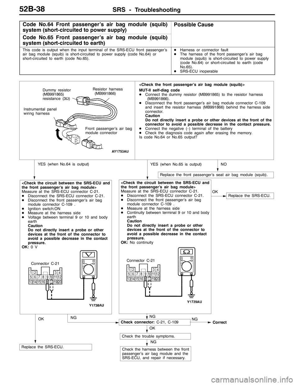
Code No.64 Front passenger’s air bag module (squib)
system (short-circuited to power supply)Possible Cause
Code No.65 Front passenger’s air bag module (squib)
system (short-circuited to earth)
This code is output when the input terminal of the SRS-ECU front passenger’s
air bag module (squib) is short-circuited to power supply (code No.64) or
short-circuited to earth (code No.65).DHarness or connector fault
DThe harness of the front passenger’s air bag
module (squib) is short-circuited to power supply
(code No.64) or short-circuited to earth (code
No.65).
DSRS-ECU inoperable
Measure at the SRS-ECU connector C-21.
DDisconnect the SRS-ECU connector C-21.
DDisconnect the front passenger’s air bag
module connector C-109 .
DMeasure at the harness side
DContinuity between terminal 9 or 10 and body
earth
Caution
Do not directly insert a probe or other
devices at the front of the connector to
avoid a possible decrease in the contact
pressure.
OK:No continuity
NO
Replace the front passenger’s seat air bag module (squib).
MUT-II self-diag code
DConnect the dummy resistor (MB991865) to the resistor harness
(MB991866).
DDisconnect the front passenger’s air bag module connector C-109
and insert the resistor harness (MB991866) behind the harness side
connector.
Caution
Do not directly insert a probe or other devices at the front of the
connector to avoid a possible decrease in the contact pressure.
DConnect the negative ( - ) terminal of the battery
DCheck the diagnosis code again after erasing the memory.
Is code No.64 or No.65 output?
YES (when No.65 is output)YES (when No.64 is output)
Replace the SRS-ECU.
Measure at the SRS-ECU connector C-21.
DDisconnect the SRS-ECU connector C-21.
DDisconnect the front passenger’s air bag
module connector C-109 .
DIgnition switch:ON
DMeasure at the harness side
DVoltage between terminal 9 or 10 and body
earth
Caution
Do not directly insert a probe or other
devices at the front of the connector to
avoid a possible decrease in the contact
pressure.
OK:0V
NG
Replace the SRS-ECU.
Correct
Check connector:C-21, C-109
Check the trouble symptoms.
Check the harness between the front
passenger’s air bag module and the
SRS-ECU, and repair if necessary.OK
NG
OK
NG
OK
NG
Resistor harness
(MB991866) Dummy resistor
(MB991865)
resistance (3Ω)
Instrumental panel
wiring harness
Front passenger’s air bag
module connector
Connector C-21Connector C-21
Page 1283 of 1449
SRS -Troubleshooting52B-39
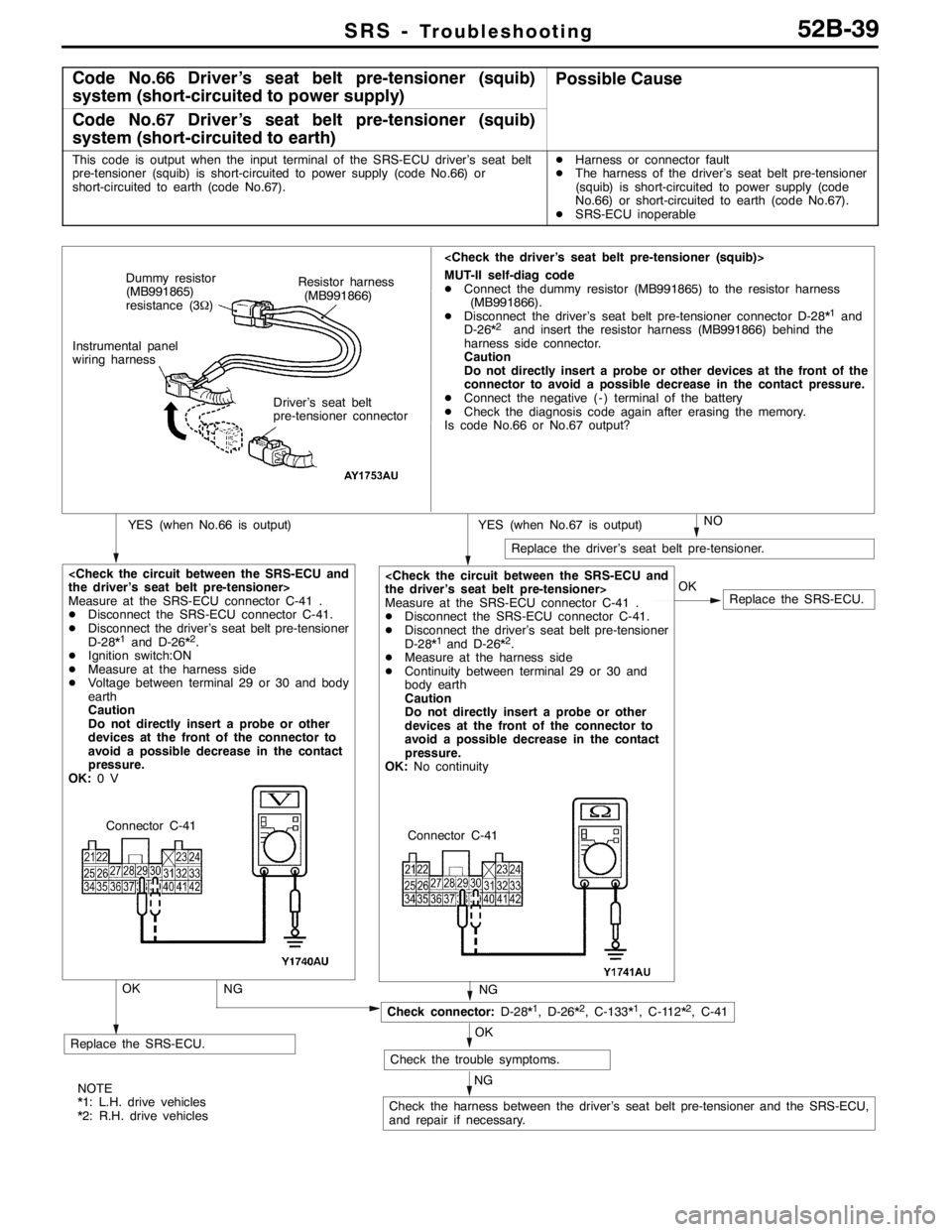
Code No.66 Driver’s seat belt pre-tensioner (squib)
system (short-circuited to power supply)Possible Cause
Code No.67 Driver’s seat belt pre-tensioner (squib)
system (short-circuited to earth)
This code is output when the input terminal of the SRS-ECU driver’s seat belt
pre-tensioner (squib) is short-circuited to power supply (code No.66) or
short-circuited to earth (code No.67).DHarness or connector fault
DThe harness of the driver’s seat belt pre-tensioner
(squib) is short-circuited to power supply (code
No.66) or short-circuited to earth (code No.67).
DSRS-ECU inoperable
Replace the SRS-ECU. OK
Measure at the SRS-ECU connector C-41 .
DDisconnect the SRS-ECU connector C-41.
DDisconnect the driver’s seat belt pre-tensioner
D-28*
1and D-26*2.
DMeasure at the harness side
DContinuity between terminal 29 or 30 and
body earth
Caution
Do not directly insert a probe or other
devices at the front of the connector to
avoid a possible decrease in the contact
pressure.
OK:No continuity
NO
Replace the driver’s seat belt pre-tensioner.
MUT-II self-diag code
DConnect the dummy resistor (MB991865) to the resistor harness
(MB991866).
DDisconnect the driver’s seat belt pre-tensioner connector D-28*
1and
D-26*2and insert the resistor harness (MB991866) behind the
harness side connector.
Caution
Do not directly insert a probe or other devices at the front of the
connector to avoid a possible decrease in the contact pressure.
DConnect the negative ( - ) terminal of the battery
DCheck the diagnosis code again after erasing the memory.
Is code No.66 or No.67 output?
YES (when No.67 is output)YES (when No.66 is output)
Replace the SRS-ECU.
Measure at the SRS-ECU connector C-41 .
DDisconnect the SRS-ECU connector C-41.
DDisconnect the driver’s seat belt pre-tensioner
D-28*
1and D-26*2.
DIgnition switch:ON
DMeasure at the harness side
DVoltage between terminal 29 or 30 and body
earth
Caution
Do not directly insert a probe or other
devices at the front of the connector to
avoid a possible decrease in the contact
pressure.
OK:0V
NG
Check connector:D-28*1, D-26*2, C-133*1, C-112*2, C-41
Check the trouble symptoms.
Check the harness between the driver’s seat belt pre-tensioner and the SRS-ECU,
and repair if necessary.
NG
OK
NG
OKResistor harness
(MB991866) Dummy resistor
(MB991865)
resistance (3Ω)
Instrumental panel
wiring harness
Driver’s seat belt
pre-tensioner connector
Connector C-41
Connector C-41
NOTE
*1: L.H. drive vehicles
*2: R.H. drive vehicles
Page 1284 of 1449
SRS -Troubleshooting52B-40
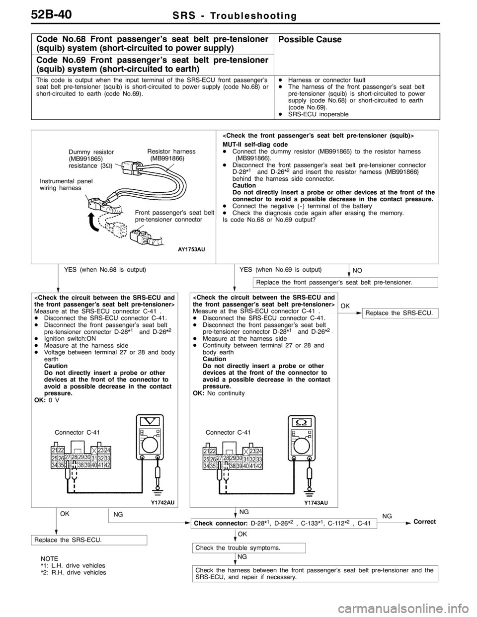
Code No.68 Front passenger’s seat belt pre-tensioner
(squib) system (short-circuited to power supply)Possible Cause
Code No.69 Front passenger’s seat belt pre-tensioner
(squib) system (short-circuited to earth)
This code is output when the input terminal of the SRS-ECU front passenger’s
seat belt pre-tensioner (squib) is short-circuited to power supply (code No.68) or
short-circuited to earth (code No.69).DHarness or connector fault
DThe harness of the front passenger’s seat belt
pre-tensioner (squib) is short-circuited to power
supply (code No.68) or short-circuited to earth
(code No.69).
DSRS-ECU inoperable
NO
Replace the front passenger’s seat belt pre-tensioner.
MUT-II self-diag code
DConnect the dummy resistor (MB991865) to the resistor harness
(MB991866).
DDisconnect the front passenger’s seat belt pre-tensioner connector
D-28*
1and D-26*2and insert the resistor harness (MB991866)
behind the harness side connector.
Caution
Do not directly insert a probe or other devices at the front of the
connector to avoid a possible decrease in the contact pressure.
DConnect the negative ( - ) terminal of the battery
DCheck the diagnosis code again after erasing the memory.
Is code No.68 or No.69 output?
YES (when No.69 is output)YES (when No.68 is output)
Replace the SRS-ECU.
Measure at the SRS-ECU connector C-41 .
DDisconnect the SRS-ECU connector C-41.
DDisconnect the front passenger’s seat belt
pre-tensioner connector D-28*
1and D-26*2.
DIgnition switch:ON
DMeasure at the harness side
DVoltage between terminal 27 or 28 and body
earth
Caution
Do not directly insert a probe or other
devices at the front of the connector to
avoid a possible decrease in the contact
pressure.
OK:0V
NG
Replace the SRS-ECU.
Correct
Check connector:D-28*1, D-26*2, C-133*1, C-112*2, C-41
Check the trouble symptoms.
Check the harness between the front passenger’s seat belt pre-tensioner and the
SRS-ECU, and repair if necessary.OK
Measure at the SRS-ECU connector C-41 .
DDisconnect the SRS-ECU connector C-41.
DDisconnect the front passenger’s seat belt
pre-tensioner connector D-28*
1and D-26*2.
DMeasure at the harness side
DContinuity between terminal 27 or 28 and
body earth
Caution
Do not directly insert a probe or other
devices at the front of the connector to
avoid a possible decrease in the contact
pressure.
OK:No continuity
NG
OK
NG
OK
NG
Resistor harness
(MB991866) Dummy resistor
(MB991865)
resistance (3Ω)
Instrumental panel
wiring harness
Front passenger’s seat belt
pre-tensioner connector
Connector C-41 Connector C-41
NOTE
*1: L.H. drive vehicles
*2: R.H. drive vehicles
Page 1292 of 1449
SRS - Post-collision Diagnosis52B-48
Steering wheel, steering column and intermediate joint
1. Check the driver’s air bag module for proper installation
to the steering wheel.
2. Check the steering wheel for noise, binds or difficult
operation and excessive free play.
Harness connector (Instrument panel wiring harness,
Floor wiring harness)
Check the harness for binds, the connector for damage and
the terminals for deformation. (Refer to P.52B-44.)
Seat belt with pre-tensioner
1. Check the seat belt for damage or deformation.
2. Check the pre-tensioner for cracks or deformation.
3. Check the harness or the connector for damage, and
the terminal for deformation.
4. Check that the unit is installed correctly to the vehicle
body.
Page 1405 of 1449

HEATER, AIR CONDITIONER AND VENTILATION-Troubleshooting55-3
TROUBLESHOOTING
BASIC FLOW OF TROUBLESHOOTING
Refer to Group 00 – How to Use Troubleshooting/Inspection Service Points.
INSPECTION CHART FOR TROUBLE SYMPTOMS
Trouble symptomInspection procedureReference page
Air conditioner not working at all155 - 3
Blower motor not working255 - 4
Air cannot be switched between inside and outside355 - 5
Rear defogger not working455-6
Cold air not coming out from the air outlet555 - 7
Magnet clutch not working normally655 - 8
Condenser fan not working at all755-9
Condenser fan not working only for LO855-10
Condenser fan not working only for HI955-11
INSPECTION PROCEDURE FOR TROUBLE SYMPTOM
Inspection procedure 1
Air conditioner not working at all
Probable cause
The A/C-ECU power supply system (including earth) may be defective.DHarness or connector fault
DA/C-ECU fault
NG
Repair
NG
Check the harness between the Ignition switch (IG2) and the
A/C-ECU, and repair if necessary.
NG
Repair
NG
Check the harness between the A/C-ECU and body earth, and
repair if necessary.
NG
Replace manual air conditioner control panel (A/C-ECU).
OK
Check the trouble
symptoms.
Check the following connectors:
(2) NG
OK
Check the trouble
symptoms.
Measure at the A/C-ECU connector C-32.
DDisconnect the connector and measure at the harness
side.
DIgnition switch: ON
(1)
OK :Battery voltage
(2)
OK :Continuity(1) NGCheck the following connectors:C-32, C-209, C-210
OK
Check the trouble
symptoms.
Page 1407 of 1449

HEATER, AIR CONDITIONER AND VENTILATION-Troubleshooting55-5
NG
Repair
NG
Repair
NG
Check the harness between the blower motor and the body
harness, and repair if necessary.
OK
Check the trouble
symptoms.
NG
Check the harness between the blower motor and the blower
relay, and repair if necessary.
OK
Check the trouble
symptoms.
Check the following connector:C-14.
(2) NG
OK
Check the trouble
symptoms.
NG
Check the harness between the blower switch and the
register, and between the register and blower motor, and
repair if necessary.
NG
Repair
OK
Measure at the blower motor connector C-14.
DDisconnect the connector and measure at the harness
side.
DIgnition switch: ON
DBlower switch position:4
(1) Voltage between terminal 1 and body earth
OK :Battery voltage
(2) Continuity between terminal 2 and body earth
OK :Continuity(1) NG
From the previous page
Check the following connectors:C-131, C-16, C-14.
Check the following connectors:C-215, C-210, C-131, C-14.
Inspection procedure 3
Air cannot be switched between inside and outside.
Probable cause
If the air cannot be switched between the inside and outside even though the
inside/outside switch is ON, the inside/outside changeover damper motor system
may be defective.DInside/outside air changeover damper motor fault
DHarness or connector fault
DA/C-ECU fault
NG
Replace
NG
Repair
OK
OK
Check the following connectors:C-10, C-107, C-32.
NG
Check the harness between the Ignition switch (IG2) and the
inside/outside air changeover damper motor, and repair if
necessary.
OK
Check the trouble
symptoms.
NG
Repair
OK
Measure at the inside/outside air changeover damper motor
connector C-10.
DDisconnect the connector and measure at the harness
side.
DIgnition switch: ON
DVoltage between terminal 7 and body earth.
OK :Battery voltageNGCheck the following connectors:C-10, C-107, C-102, C-209,
C-210.
Check the inside/outside air changeover damper motor (Refer
to P.55-32.).
NG
Repair
OK
Replace manual air conditioner control panel (A/C-ECU).
NG
Check the trouble
symptoms.
Check the harness between the inside/outside air changeover
damper motor and the A/C-ECU.
Page 1408 of 1449
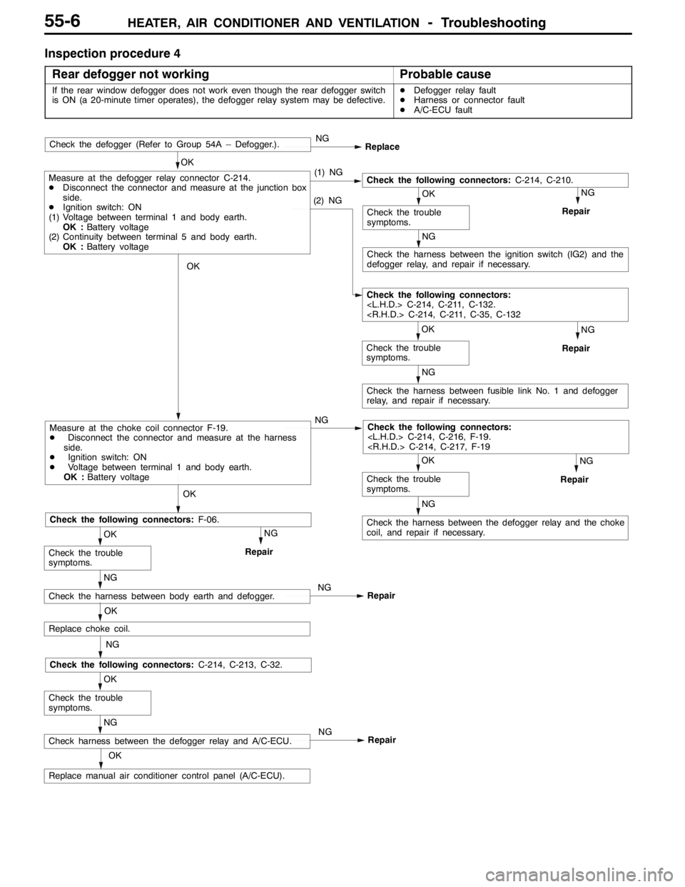
HEATER, AIR CONDITIONER AND VENTILATION-Troubleshooting55-6
Inspection procedure 4
Rear defogger not working
Probable cause
If the rear window defogger does not work even though the rear defogger switch
is ON (a 20-minute timer operates), the defogger relay system may be defective.DDefogger relay fault
DHarness or connector fault
DA/C-ECU fault
NG
Check the harness between the ignition switch (IG2) and the
defogger relay, and repair if necessary.
NG
Repair
Replace manual air conditioner control panel (A/C-ECU).
OK
OK
Check the trouble
symptoms.
NG
Check the following connectors:C-214, C-213, C-32.
OK
Check the trouble
symptoms.
NG
Replace
NG
Repair
NG
Check the harness between fusible link No. 1 and defogger
relay, and repair if necessary.
OK
Check the trouble
symptoms.
Check the following connectors:
(2) NG
NG
Repair
NG
Check the harness between the defogger relay and the choke
coil, and repair if necessary.
OK
Check the trouble
symptoms.
Check the following connectors:
NG
Repair
Check the following connectors:F-06.
OK
OK
Measure at the choke coil connector F-19.
DDisconnect the connector and measure at the harness
side.
DIgnition switch: ON
DVoltage between terminal 1 and body earth.
OK :Battery voltageNG
OK
Measure at the defogger relay connector C-214.
DDisconnect the connector and measure at the junction box
side.
DIgnition switch: ON
(1) Voltage between terminal 1 and body earth.
OK :Battery voltage
(2) Continuity between terminal 5 and body earth.
OK :Battery voltage(1) NGCheck the following connectors:C-214, C-210.
OK
Check the trouble
symptoms.
NG
RepairNG
Check the harness between body earth and defogger.
NG
RepairNG
Check harness between the defogger relay and A/C-ECU.
OK
Replace choke coil.
Check the defogger (Refer to Group 54A – Defogger.).