Engine oil pump MITSUBISHI LANCER EVOLUTION 2007 Service Repair Manual
[x] Cancel search | Manufacturer: MITSUBISHI, Model Year: 2007, Model line: LANCER EVOLUTION, Model: MITSUBISHI LANCER EVOLUTION 2007Pages: 1449, PDF Size: 56.82 MB
Page 138 of 1449
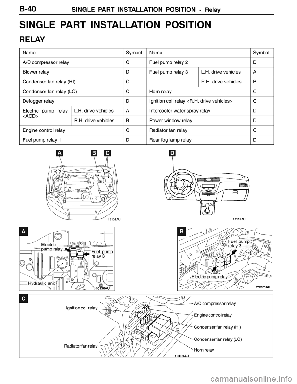
SINGLE PART INSTALLATION POSITION -Relay
A
Electric
pump relay
Hydraulic unit
Fuel pump
relay 3
B
Electric pump relay
Fuel pump
relay 3
C
Ignition coil relay
Radiator fan relay
A/C compressor relay
Engine control relay
Condenser fan relay (HI)
Condenser fan relay (LO)
Horn relay
B-40
SINGLE PART INSTALLATION POSITION
RELAY
NameSymbolNameSymbol
A/C compressor relayCFuel pump relay 2D
Blower relayDFuel pump relay 3L.H. drive vehiclesA
Condenser fan relay (HI)CR.H. drive vehiclesB
Condenser fan relay (LO)CHorn relayC
Defogger relayDIgnition coil relay
Electric pump relay
L.H. drive vehiclesAIntercooler water spray relayD
Engine control relayCRadiator fan relayC
Fuel pump relay 1DRear fog lamp relayD
ABCD
Page 169 of 1449

CIRCUIT DIAGRAMSB-71
MULTI-PURPOSE FUSE (In junction block)
Power supply
circuitNo.Rated
capacity (A)Identification
colourCircuit
Ignition
switch
IG1110RedIgnition coil
switch
27.5BrownColumn switch, combination meter, ETACS-ECU,
SRS-ECU, vehicle speed sensor and ACD mode
changeover switch
37.5BrownETACS-ECU and SRS-ECU
4---
IG257.5BrownA/C compressor relay, A/C-ECU, blower relay,
condenser fan relay, defogger relay, front-ECU,
4WD-ECU, steering wheel sensor and inter cooler
water splay relay
Multi-purpose fuse
No. 20 (Defogger
relay)6---
Ignition
switch
ACC720YellowFront-ECU and windshield wiper motor
switch
IG187.5BrownEngine-ECU and fuel pump relay (1) and fuel pump
relay (2)
ACC915BlueCigarette lighter
10---
117.5BrownA/C-ECU and remote controlled mirror switch
IG2127.5BrownABS-ECU, G-sensor (longitudinal) and G-sensor
(lateral)
ACC13---
14---
Fusible link No. 1
Battery/alternator
1515BlueDiagnosis connector
Battery/alternator
1610RedRear fog lamp relay
1710RedETACS-ECU
18---
1930GreenBlower motor and resistor
2030GreenDefogger
Page 359 of 1449

INDEX - In order of connector No.C-3
Wiring diagram
page Circuit diagram page Parts name Connector
No.
BB-108Back-up lamp switchB-142,143B-12,16
B-110Engine coolant temperature gauge unitB-148,152B-12,16
B-112EGR solenoid valveB-91,99B-12,16
B-114Ignition coil 1B-82,83B-12,16
B-115Idle speed control servoB-88,96B-12,16
B-116Camshaft position sensorB-88,96B-12,16
B-118Engine coolant temperature sensorB-89,97B-12,16
B-119Ignition coil 2B-82,83B-12,16
B-121Crank angle sensorB-88,96B-13,16
B-122Detonation sensorB-89,97B-13,17
B-123ABS-ECUB-198,200,201,202,203,204,205,206,
208,209,210,211,229,232,233,239,
242,243B-13,17
B-138ResistorB-89,97B-13,17
B-139Electric pump relay
B-140Fuel pump relay 3B-93,101B-13,17
B-141Fuel pump resistorB-93,101B-13,17
B-142Secondary air control solenoid valveB-91,99B-13,17
CC-01Combination meterB-84,87,95,103,106,118,122,126,129,
135,139,148,149,152,153,156,157,
198,206,214,222,230,240,248,250,
256, 258B-18,24
C-02Combination meterB-110,115,118,122,126,129,135,139,
148,149,152,153,156,157,198,206,
248, 250,256,258B-18,24
C-03Hazard warning switchB-136,140B-18,24
C-04ClockB-194B-18,24
C-05J/C (1)B-56,62,93,101,104,107,111,112,115,
116,118,122,124,125,127,128,131,
133,136,137,140,141,148,152,153,
156,158,164,170,172,175,181,185,
187,191,194,195,196,197,212,214,
220,222,228,230,238,240,257B-18,24
C-08J/C (3)B-58,64,95,104,105,107,108,112,113,
116,117,119,123,124,125,126,127,
128,129,131,133,136,137,140,141,
149,153,159,164,165,171,172,173,
175,180,181,185,187,188,189,191,
193,194,195,202,210,214,218,222,
226,227,230,236,240,246,247,253,
255,257,258B-18,24
Page 414 of 1449
ENGINE -On-vehicle Service11A-8
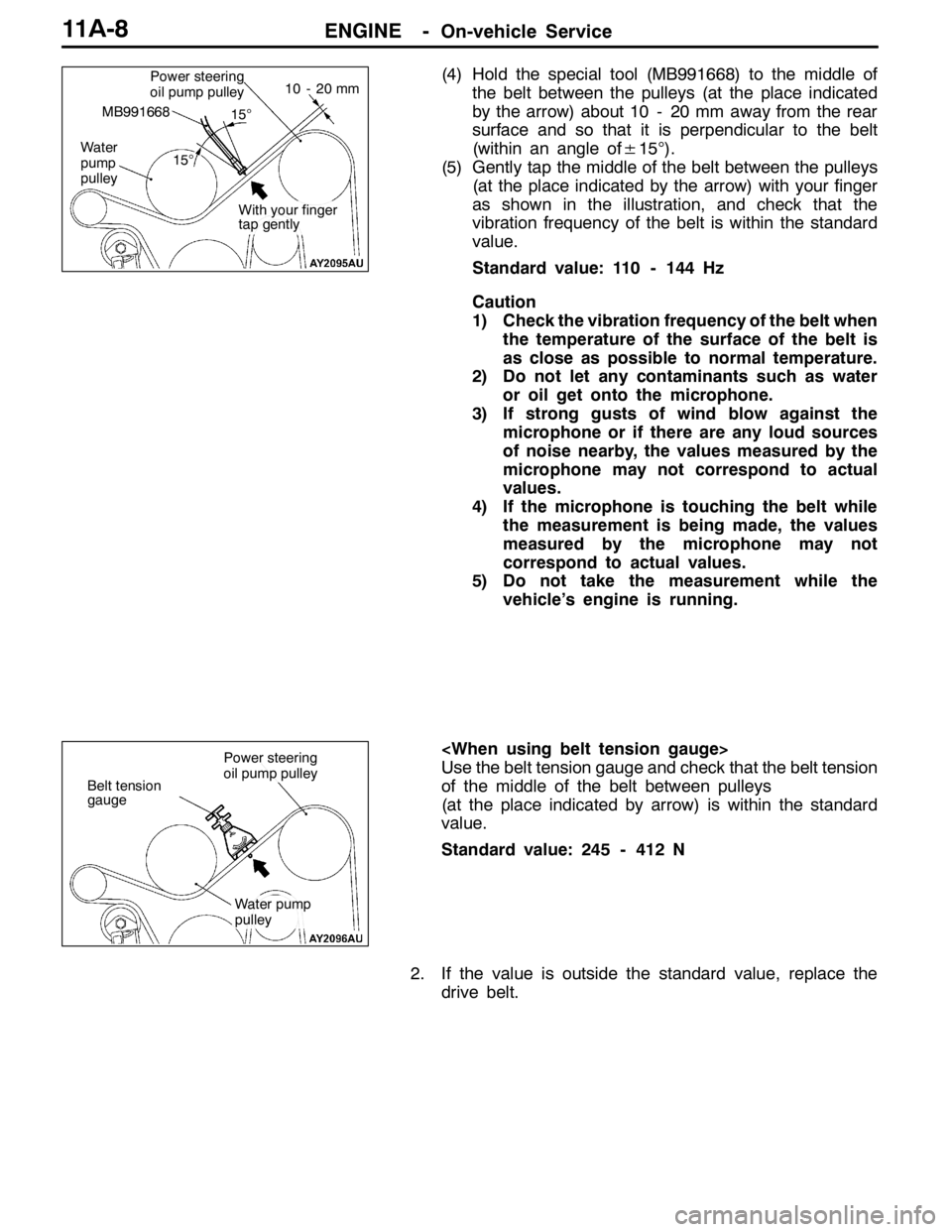
(4) Hold the special tool (MB991668) to the middle of
the belt between the pulleys (at the place indicated
by the arrow) about 10 - 20 mm away from the rear
surface and so that it is perpendicular to the belt
(within an angle of±15°).
(5) Gently tap the middle of the belt between the pulleys
(at the place indicated by the arrow) with your finger
as shown in the illustration, and check that the
vibration frequency of the belt is within the standard
value.
Standard value: 110 - 144 Hz
Caution
1) Check the vibration frequency of the belt when
the temperature of the surface of the belt is
as close as possible to normal temperature.
2) Do not let any contaminants such as water
or oil get onto the microphone.
3) If strong gusts of wind blow against the
microphone or if there are any loud sources
of noise nearby, the values measured by the
microphone may not correspond to actual
values.
4) If the microphone is touching the belt while
the measurement is being made, the values
measured by the microphone may not
correspond to actual values.
5) Do not take the measurement while the
vehicle’s engine is running.
Use the belt tension gauge and check that the belt tension
of the middle of the belt between pulleys
(at the place indicated by arrow) is within the standard
value.
Standard value: 245 - 412 N
2. If the value is outside the standard value, replace the
drive belt.Power steering
oil pump pulley
Water
pump
pulley
MB991668
10 - 20 mm
15°
15°
With your finger
tap gently
Belt tension
gauge
Power steering
oil pump pulley
Water pump
pulley
Page 445 of 1449
ENGINE -Timing Belt and Timing Belt B11A-39
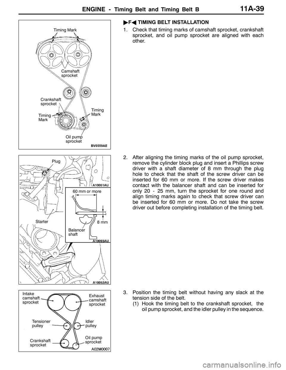
"FATIMING BELT INSTALLATION
1. Check that timing marks of camshaft sprocket, crankshaft
sprocket, and oil pump sprocket are aligned with each
other.
2. After aligning the timing marks of the oil pump sprocket,
remove the cylinder block plug and insert a Phillips screw
driver with a shaft diameter of 8 mm through the plug
hole to check that the shaft of the screw driver can be
inserted for 60 mm or more. If the screw driver makes
contact with the balancer shaft and can be inserted for
only 20 - 25 mm, turn the sprocket for one round and
align timing marks again to check that screw driver can
be inserted for 60 mm or more. Do not take the screw
driver out before completing installation of the timing belt.
3. Position the timing belt without having any slack at the
tension side of the belt.
(1) Hook the timing belt to the crankshaft sprocket, the
oil pump sprocket, and the idler pulley in the sequence.
Timing Mark
Timing
Mark
Timing
Mark
Crankshaft
sprocket
Oil pump
sprocket
Camshaft
sprocket
8mm
60 mm or more
Balancer
shaft
Plug
Starter
Intake
camshaft
sprocketExhaust
camshaft
sprocket
Idler
pulley
Oil pump
sprocketCrankshaft
sprocket
Tensioner
pulley
Page 451 of 1449
ENGINE -Engine Assembly11A-45
67±7 N·m*
23 33
24 29
3031
32
2722
98±10 N·m*5.0±1.0 N·m
(Engine oil)
20
21 19
25
42±2 N·m22±4 N·m
40±5 N·m
42±2 N·m
26
26
2834
22±4 N·m12±2 N·m
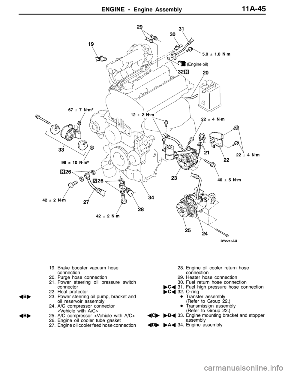
19. Brake booster vacuum hose
connection
20. Purge hose connection
21. Power steering oil pressure switch
connector
22. Heat protector
AB"23. Power steering oil pump, bracket and
oil reservoir assembly
24. A/C compressor connector
AB"25. A/C compressor
26. Engine oil cooler tube gasket
27. Engine oil cooler feed hose connection28. Engine oil cooler return hose
connection
29. Heater hose connection
30. Fuel return hose connection
"CA31. Fuel high pressure hose connection
"CA32. O-ring
DTransfer assembly
(Refer to Group 22.)
DTransmission assembly
(Refer to Group 22.)
AC""BA33. Engine mounting bracket and stopper
assembly
AD""AA34. Engine assembly
Page 452 of 1449
ENGINE -Engine Assembly11A-46
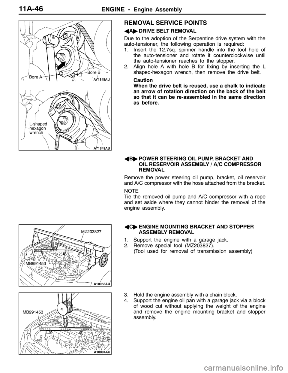
REMOVAL SERVICE POINTS
AA"DRIVE BELT REMOVAL
Due to the adoption of the Serpentine drive system with the
auto-tensioner, the following operation is required:
1. Insert the 12.7sq. spinner handle into the tool hole of
the auto-tensioner and rotate it counterclockwise until
the auto-tensioner reaches to the stopper.
2. Align hole A with hole B for fixing by inserting the L
shaped-hexagon wrench, then remove the drive belt.
Caution
When the drive belt is reused, use a chalk to indicate
an arrow of rotation direction on the back of the belt
so that it can be re-assembled in the same direction
as before.
AB"POWER STEERING OIL PUMP, BRACKET AND
OIL RESERVOIR ASSEMBLY / A/C COMPRESSOR
REMOVAL
Remove the power steering oil pump, bracket, oil reservoir
and A/C compressor with the hose attached from the bracket.
NOTE
Tie the removed oil pump and A/C compressor with a rope
and set aside where they cannot hinder the removal of the
engine assembly.
AC"ENGINE MOUNTING BRACKET AND STOPPER
ASSEMBLY REMOVAL
1. Support the engine with a garage jack.
2. Remove special tool (MZ203827).
(Tool used for removal of transmission assembly)
3. Hold the engine assembly with a chain block.
4. Support the engine oil pan with a garage jack via a block
of wood cut without applying the weight of the engine
and remove the engine mounting bracket and stopper
assembly.
Bore A
L-shaped
hexagon
wrench
Bore B
MZ203827
MB991453
MB991453
Page 455 of 1449

11B-1
ENGINE
OVERHAUL
CONTENTS
GENERAL DESCRIPTION 2...................
SPECIFICATIONS 3..........................
Service Specifications 3.........................
Machining Standards 5.........................
Tightening Torque 5............................
Sealants 8.....................................
Form-In-Place Gasket 8........................
SPECIAL TOOLS 9...........................
ALTERNATOR AND IGNITION SYSTEM 12....
TIMING BELT 13.............................
FUEL SYSTEM 26............................SECONDARY AIR SYSTEM AND INTAKE
MANIFOLD 28...............................
EXHAUST MANIFOLD 30.....................
WATER PUMP AND WATER HOSE 32........
ROCKER ARMS AND CAMSHAFT 34.........
CYLINDER HEAD AND VALVE 40.............
OIL PUMP AND OIL PAN 47.................
PISTON AND CONNECTING ROD 56..........
CRANKSHAFT AND CYLINDER BLOCK 64....
Page 458 of 1449

ENGINE OVERHAUL -Specifications11B-4
Unit: mm
Items
Standard valueLimited value
Oil pump, oil pan
Oil pump
Side clearance
Drive gear
Driven gear
0.08 - 0.14
0.06 - 0.12-
-
Piston, connecting rod
Piston
Press-in load N
Piston ring
Clearance between ring and ring groove
No. 1 ring
No. 2 ring
Closed gap
No. 1 ring
No. 2 ring
Oil
Connecting rod
Large end thrust clearance
Crankshaft
Pin section oil clearance
7,355 - 17,162
0.03 - 0.07
0.02 - 0.06
0.20 - 0.30
0.35 - 0.50
0.10 - 0.40
0.10 - 0.25
0.03 - 0.05-
0.1
0.1
0.8
0.8
1.0
0.4
0.1
Crankshaft, cylinder block
Crankshaft
End play
Journal section oil clearance
Cylinder block
Upper surface strain
Upper surface grinding limit (in combination with combined cylinder head)
Cylinder bore
Cylindricity
Clearance between piston and cylinder
0.05 - 0.25
0.03 - 0.04
0.05
-
85.0
0.01 or less
0.02 - 0.040.4
0.1
0.1
0.2
-
-
-
Turbocharger
Waste gate actuator operation pressure100 kPa-
Alternator
Alternator
Rotor coil resistanceΩ
Brush protrusion length
3-5
--
2
Starter motor
Starter motor
Deviation on commutator periphery
Commutator outer diameter
Undercut depth
0.05
29.4
0.50.1
28.8
0.2
Page 459 of 1449

ENGINE OVERHAUL -Specifications11B-5
MACHINING STANDARDS
Unit: mm
Items
Standard valueLimited value
Cylinder head, valve
Cylinder head
Oversize valve guide hole diameter
0.05 O.S.
0.25 O.S.
0.50 O.S.
Oversize valve seat hole diameter
Intake
0.3 O.S.
0.6 O.S.
Exhaust
0.3 O.S.
0.6 O.S.
12.05 - 12.07
12.25 - 12.27
12.50 - 12.52
35.30 - 35.33
35.60 - 35.63
33.30 - 33.33
33.60 - 33.63-
-
-
-
-
-
-
TIGHTENING TORQUE
ItemsTightening torque N·m
Alternator, ignition system
Oil level gauge guide bolt13±1
Water pump pulley bolt8.8±1.0
Alternator brace bolt (flange)23±3
Alternator brace bolt (washer)22±4
Alternator nut44±10
Crankshaft pulley bolt25±4
Center cover bolt3±0.5
Ignition coil bolt10±2
Spark plug25±5
Connector bracket bolt8.8±1.0
Timing belt
Timing belt cover bolt (flange)11±1
Timing belt cover bolt (washer)9±1
Power steering pump bracket bolt49±9
Tensioner pulley bolt49±6
Tensioner arm bolt21±4
Auto tensioner bolt23±3
Idler pulley bolt35±6
Crank angle sensor bolt8.8±1.0
Oil pump sprocket nut54±5
Crankshaft bolt162±5
Tensioner B bolt19±3
Counter balance shaft sprocket bolt46±3
Rocker cover bolt3.5±0.5
Engine support bracket bolt49±5