coolant MITSUBISHI LANCER EVOLUTION 2007 Service Repair Manual
[x] Cancel search | Manufacturer: MITSUBISHI, Model Year: 2007, Model line: LANCER EVOLUTION, Model: MITSUBISHI LANCER EVOLUTION 2007Pages: 1449, PDF Size: 56.82 MB
Page 90 of 1449
HOW TO READ THE WIRING DIAGRAMS -How to Read Circuit DiagramsA-4
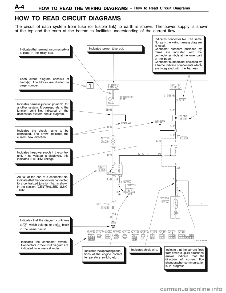
HOW TO READ CIRCUIT DIAGRAMS
The circuit of each system from fuse (or fusible link) to earth is shown. The power supply is shown
at the top and the earth at the bottom to facilitate understanding of the current flow.
Indicates the power supply in the control
unit. If no voltage is displayed, this
indicates SYSTEM voltage.
Indicates power take out.
Indicates connector No. The same
No. as in the wiring harness diagram
is used.
Connector numbers enclosed by
frame are indicated with the
connector symbols at the lower part
of the page.
Connector numbers not enclosed by
a frame indicate components which
are integrated with the harness.
Indicates harness junction point No. for
another system. It corresponds to the
junction point No. indicated on the
destination system circuit diagram.
Indicates the circuit name to be
connected. The arrow indicates the
current flow direction.
An “X” at the end of a connector No.
indicates that the connector is connected
to a centralized junction that is shown
in the section “CENTRALIZED JUNC-
TION”.
Indicates the operating condi-
tions of the engine coolant
temperature switch, etc.
Indicates the connector symbol.
Connectors in the circuit diagram are
indicated in numerical order.
Indicates shield wire.
Indicates that terminal is connected via
a plate in the relay box.
Each circuit diagram consists of
block(s). The blocks are divided by
page number.
Indicates that the diagram continues
at
Awhich belongs to the block
in the same circuit.2
Indicate that the current flows
from down to up. Bi-directional
arrows indicate that the
direction of current flow
changes when communication
is in progress.
Page 96 of 1449

HOW TO READ THE WIRING DIAGRAMS -Abbreviation SymbolsA-10
ABBREVIATION SYMBOLS
The abbreviation symbols used in wiring diagrams are defined below.
1. Abbreviation symbols used for system name
Abbreviation
symbolsMeaningAbbreviation
symbolsMeaning
A/CAir conditionerEGRExhaust gas recirculation
ABSAnti-skid braking systemETACSElectronic time alarm control system
ACDActive center differentialSRSSupplemental restraint system
AY CActive yaw control
2. Abbreviation symbols used for combination meters
Abbreviation
symbolsMeaningAbbreviation
symbolsMeaning
ABSAnti-skid braking system warning lampSNOWActive center differential mode indicator
lamp
BEAMHigh beam indicator lampSPEEDSpeedmeter
BRAKEBrake warning lampSRSSupplemental restraint system warning
lamp
CHECK
ENGINECheck engine warning lampTARMACActive center differential mode indicator
lamp
CHGCharging warning lampT/GAEngine coolant temperature gauge
DOORDoor-ajar warning lampTACHOTachometer
F/GAFuel gaugeTAILTail, position and licence plate indicator
lamp
FRONT FOGFront fog indicator lamp
lamp
FUELLow fuel warning lampTRIPTripmeter
GRAVELActive center differential mode indicator
lampTURN (LH)Turn signal indicator lamp (LH)
ODOOdometerTURN (RH)Trun signal indicator lamp (RH)
OILOil pressure warning lampWATER
SPRAY
Intercooler water spray indicator lamp
REAR FOGRear fog indicator lamp
SPRAY
3. Abbreviation symbols used for switched and relay
Name of switches and
relaysAbbreviation
symbolsOperation
Blower switchLOBlower operates at low speed
MLBlower operates at medium low speed
MHBlower operates at medium high speed
HIBlower operates at high speed
Page 110 of 1449
WIRING HARNESS CONFIGURATION DIAGRAMS
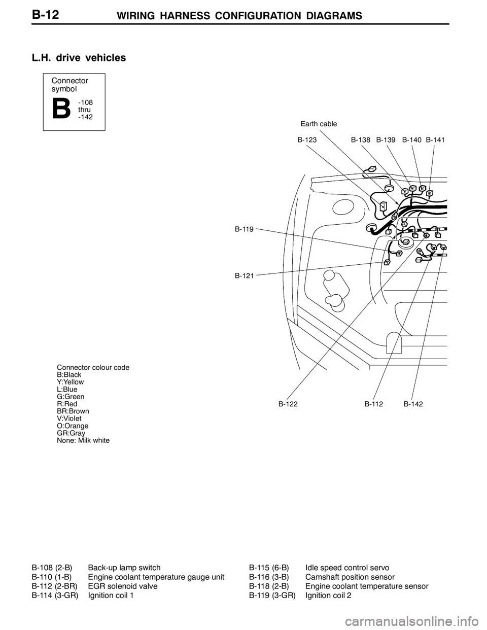
Connector
symbol
-108
thru
-142
BEarth cable
B-123B-138B-139B-140B-141
B-119
B-121
B-122B-112B-142
Connector colour code
B:Black
Y:Yellow
L:Blue
G:Green
R:Red
BR:Brown
V:Violet
O:Orange
GR:Gray
None: Milk white
B-12
L.H. drive vehicles
B-108 (2-B) Back-up lamp switch
B-110 (1-B) Engine coolant temperature gauge unit
B-112 (2-BR) EGR solenoid valve
B-114 (3-GR) Ignition coil 1B-115 (6-B) Idle speed control servo
B-116 (3-B) Camshaft position sensor
B-118 (2-B) Engine coolant temperature sensor
B-119 (3-GR) Ignition coil 2
Page 114 of 1449
WIRING HARNESS CONFIGURATION DIAGRAMS
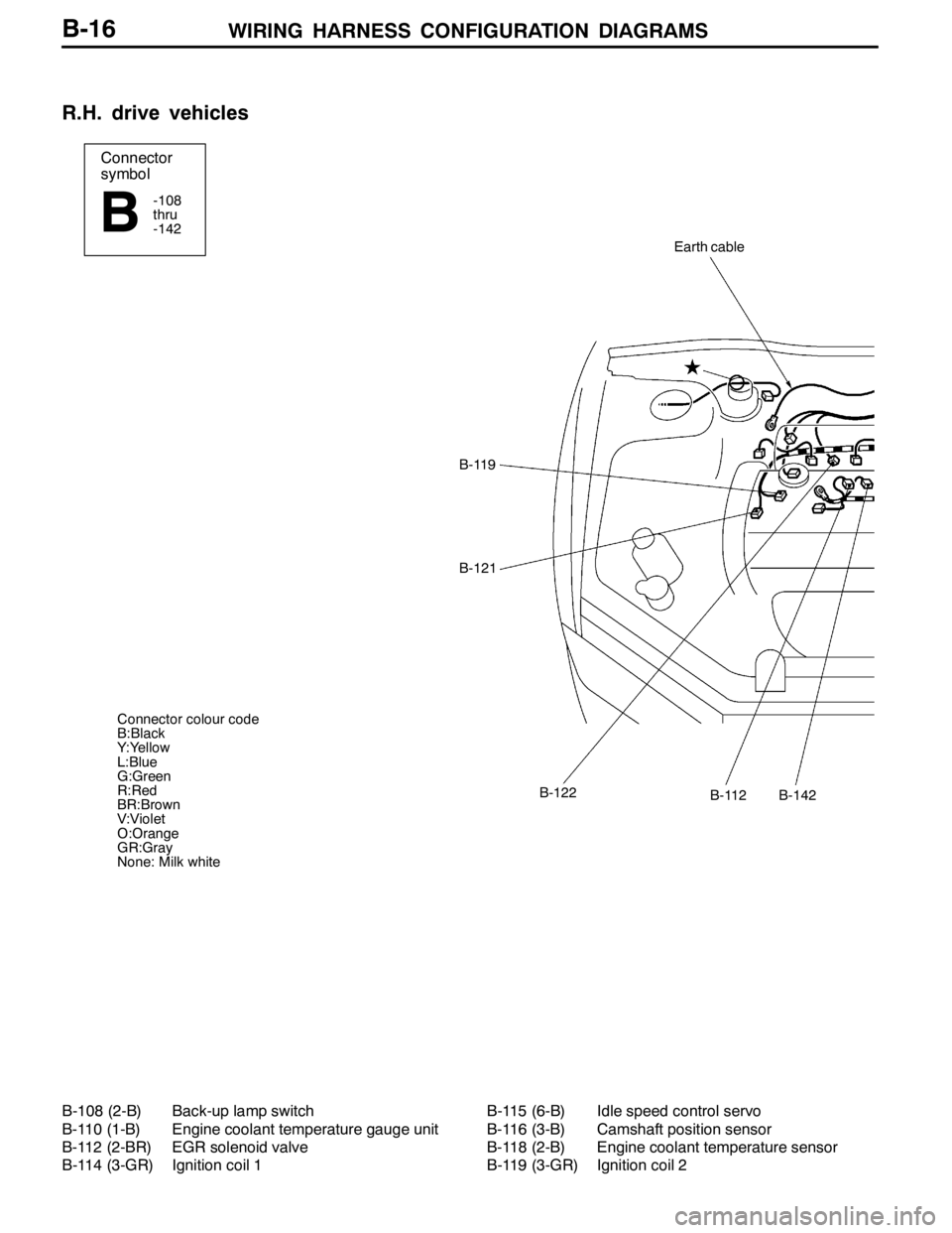
Connector
symbol
-108
thru
-142
B
Earth cable
B-119
B-121
B-112B-122B-142
Connector colour code
B:Black
Y:Yellow
L:Blue
G:Green
R:Red
BR:Brown
V:Violet
O:Orange
GR:Gray
None: Milk white
B-16
R.H. drive vehicles
B-108 (2-B) Back-up lamp switch
B-110 (1-B) Engine coolant temperature gauge unit
B-112 (2-BR) EGR solenoid valve
B-114 (3-GR) Ignition coil 1B-115 (6-B) Idle speed control servo
B-116 (3-B) Camshaft position sensor
B-118 (2-B) Engine coolant temperature sensor
B-119 (3-GR) Ignition coil 2
Page 141 of 1449
SINGLE PART INSTALLATION POSITION -ECU/Sensor
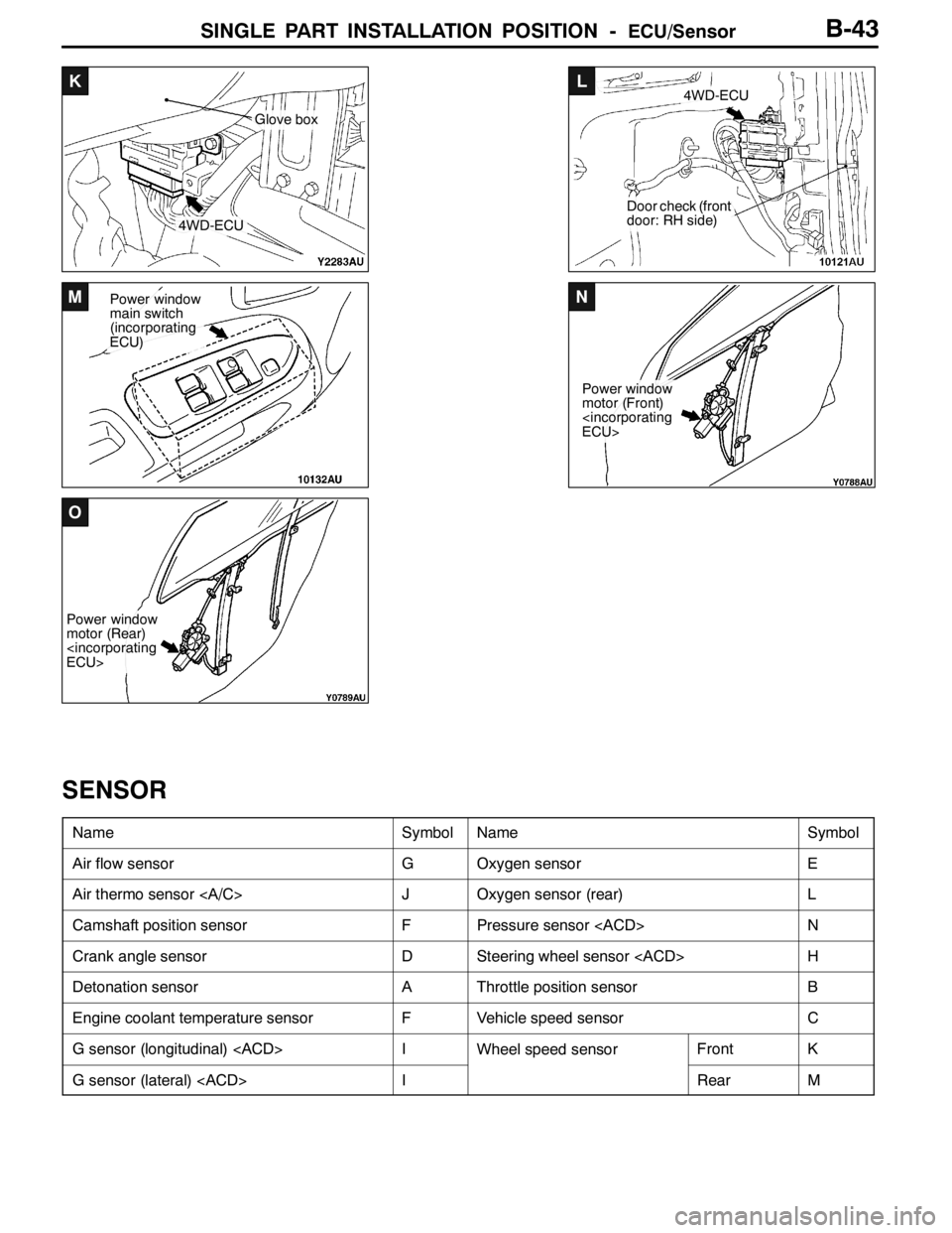
K
4WD-ECU
Glove box
L
Door check (front
door: RH side)
4WD-ECU
MPower window
main switch
(incorporating
ECU)N
Power window
motor (Front)
O
Power window
motor (Rear)
B-43
SENSOR
NameSymbolNameSymbol
Air flow sensorGOxygen sensorE
Air thermo sensor JOxygen sensor (rear)L
Camshaft position sensorFPressure sensor
Crank angle sensorDSteering wheel sensor
Detonation sensorAThrottle position sensorB
Engine coolant temperature sensorFVehicle speed sensorC
G sensor (longitudinal)
G sensor (lateral)
Page 143 of 1449
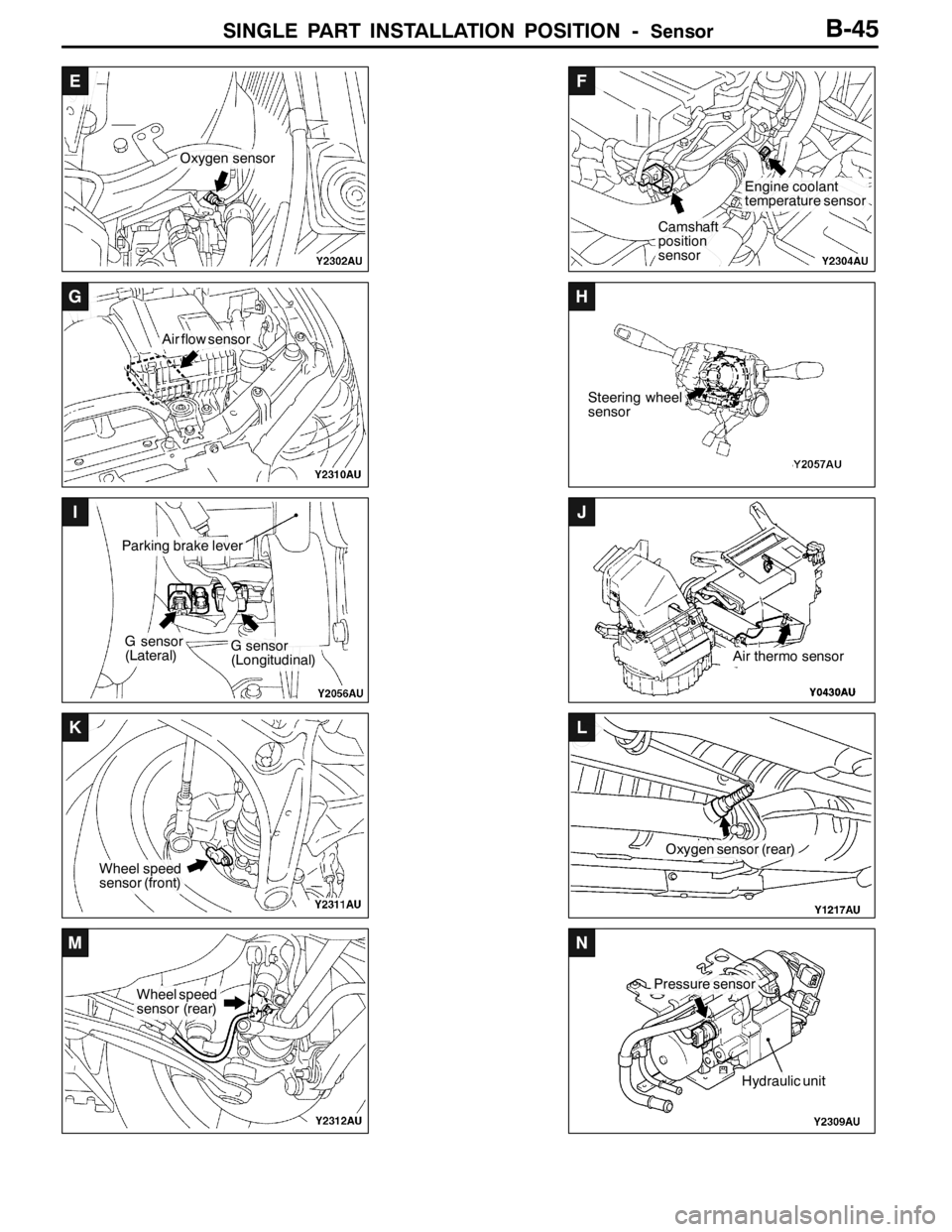
SINGLE PART INSTALLATION POSITION -Sensor
E
Oxygen sensor
F
Camshaft
position
sensor
Engine coolant
temperature sensor
G
Air flow sensor
H
Steering wheel
sensor
I
G sensor
(Lateral)
Parking brake lever
G sensor
(Longitudinal)
J
Air thermo sensor
K
Wheel speed
sensor (front)
L
Oxygen sensor (rear)
M
Wheel speed
sensor (rear)
N
Pressure sensor
Hydraulic unit
B-45
Page 245 of 1449

CIRCUIT DIAGRAMSB-147
METER AND GAUGE (See P.B-148,152.)
OPERATION
DWhen the ignition switch is at the “ON” position,
the fuel gauge is activated.
DWhen there is much fuel, the unit’s resistance
is small and the current flowing in the circuit
is great, so the gauge’s indicator indicates in
the “Full” area.
DWhen there is little fuel, the unit’s resistance
is high and the current flowing in the circuit
is small, so the gauge’s indicator indicates in
the “Empty” area.
DWhen the ignition switch is at the “ON” position,
the engine coolant temperature gauge is
activated.
DWhen the engine coolant temperature is high,
the unit’s resistance is low and there is a great
flow of current in the circuit, so the gauge’s
indicator indicates in the “H” area.
DWhen the engine coolant temperature is low,
the unit’s resistance is high and there is a small
flow of current in the circuit, so the gauge’s
indicator indicates in the “C” area.TROUBLESHOOTING HINTS
1. Fuel gauge does not operate, or registers
incorrectly.
(1) The fuel gauge indicates “F” when the fuel
gauge unit (sub) connector is disconnected
and the “1” terminal is earthed.
DCheck fuel gauge.
2. Engine coolant temperature gauge does not
operate, or registers incorrectly.
(1) When the engine coolant temperature
gauge is earthed with its connector
unplugged, it registers “H”.
DCheck engine coolant temperature
gauge unit.
Page 359 of 1449

INDEX - In order of connector No.C-3
Wiring diagram
page Circuit diagram page Parts name Connector
No.
BB-108Back-up lamp switchB-142,143B-12,16
B-110Engine coolant temperature gauge unitB-148,152B-12,16
B-112EGR solenoid valveB-91,99B-12,16
B-114Ignition coil 1B-82,83B-12,16
B-115Idle speed control servoB-88,96B-12,16
B-116Camshaft position sensorB-88,96B-12,16
B-118Engine coolant temperature sensorB-89,97B-12,16
B-119Ignition coil 2B-82,83B-12,16
B-121Crank angle sensorB-88,96B-13,16
B-122Detonation sensorB-89,97B-13,17
B-123ABS-ECUB-198,200,201,202,203,204,205,206,
208,209,210,211,229,232,233,239,
242,243B-13,17
B-138ResistorB-89,97B-13,17
B-139Electric pump relay
B-140Fuel pump relay 3B-93,101B-13,17
B-141Fuel pump resistorB-93,101B-13,17
B-142Secondary air control solenoid valveB-91,99B-13,17
CC-01Combination meterB-84,87,95,103,106,118,122,126,129,
135,139,148,149,152,153,156,157,
198,206,214,222,230,240,248,250,
256, 258B-18,24
C-02Combination meterB-110,115,118,122,126,129,135,139,
148,149,152,153,156,157,198,206,
248, 250,256,258B-18,24
C-03Hazard warning switchB-136,140B-18,24
C-04ClockB-194B-18,24
C-05J/C (1)B-56,62,93,101,104,107,111,112,115,
116,118,122,124,125,127,128,131,
133,136,137,140,141,148,152,153,
156,158,164,170,172,175,181,185,
187,191,194,195,196,197,212,214,
220,222,228,230,238,240,257B-18,24
C-08J/C (3)B-58,64,95,104,105,107,108,112,113,
116,117,119,123,124,125,126,127,
128,129,131,133,136,137,140,141,
149,153,159,164,165,171,172,173,
175,180,181,185,187,188,189,191,
193,194,195,202,210,214,218,222,
226,227,230,236,240,246,247,253,
255,257,258B-18,24
Page 369 of 1449

INDEX - In order of parts nameC-13
Wiring diagram
page Circuit diagram page Connector
No. Parts name
DDoor switch (Rear:LH)D-08B-120,121B-30,32
Door switch (Rear:RH)D-06B-120,121B-30,32
Dual pressure switchA-36B-178,184B-7,9
EEGR solenoid valveB-112B-91,99B-12,16
Electric pump
Electric pump relay
Engine control relayB-11XB-73,86,94,252,254B-10,14
Engine coolant temperature gauge unitB-110B-148,152B-12,16
Engine coolant temperature sensorB-118B-89,97B-12,16
Engine speed detection connectorB-05XB-73,82,83,90,98B-10,14
Engine-ECUC-115B-87,88,89,90,91,92,93,95,96,97,98,
99,100,101,215,223,231,241,257B-20,26
Engine-ECUC-118B-82,83,88,90,91,92,93,96,98,99,100,
101,149,153,252,254,256B-20,26
Engine-ECUC-122B-84,86,87,90,91,93,94,95,98,99,101,
177,178,183,184,252,254,256,257B-20,26
Engine-ECUC-126B-82,83,86,88,89,90,91,93,94,96,97,
98,99, 101,102,178,184B-20,26
ETACS-ECUC-226B-54,55,105,108,112,113,116,117,118,
119,120,121,122,123,125,126,128,
129,134,136,137,138,140,141,158,
164,165, 170,171,172,173,188,189B-23,29
ETACS-ECUC-227B-125,128,170,172B-23,29
ETACS-ECUC-228B-105,108,112,113,116,117,118,119,
122,123,125,126,128,129,136,137,
140,141,158,159,164,165,170,171,
172,173, 188,189,258B-23,29
FFan controllerA-21B-102,176,182B-7,8
Floor wiring harness (LH) and 4WD
wiring harness combination
Floor wiring harness (LH) and bumper
wiring harness combinationF-14B-110,114B-38,39
Floor wiring harness (LH) and J/B
combination
158,171,185B-23
Floor wiring harness (LH) and rear door
wiring harness (LH) combinationD-12B-161,167,171,173B-30,32
Floor wiring harness (RH) and fuel
wiring harness combinationD-29B-93,101B-31,33
Floor wiring harness (RH) and fuel
wiring harness combinationD-30B-93,101,148,152,156,203,211,217,
225,233,243B-31,33
Page 397 of 1449

GENERAL -Precautions Before ServiceGENERAL -Precautions Before Service00-19
SERVICING THE ELECTRICAL SYSTEM
Before replacing a component related to the electrical system
and before undertaking any repair procedures involving the
electrical system, be sure to first disconnect the negative
( - ) cable from the battery in order to avoid damage caused
by short-circuiting.
Caution
Before connecting or disconnecting the negative ( - ) cable,
be sure to turn off the ignition switch and the lighting
switch.
(If this is not done, there is the possibility of
semiconductor parts being damaged.)
APPLICATION OF ANTI-CORROSION AGENTS
AND UNDERCOATS
If oil or grease gets onto the oxygen sensor, it will cause
a drop in the performance of the sensor.
Cover the oxygen sensor with a protective cover when applying
anti-corrosion agents and undercoats.
PRE-INSPECTION CONDITION
“Pre-inspection condition” refers to the condition that the
vehicle must be in before proper engine inspection can be
carried out. If you see the words “Set the vehicle to the
pre-inspection condition”. in this manual, it means to set the
vehicle to the following condition.
DEngine coolant temperature: 80 to 90_C
DLamps, electric cooling fan and all accessories: OFF
DM/T: Neutral
DA/T: P range
VEHICLE WASHING
If high-pressure car-washing equipment or steam car-washing
equipment is used to wash the vehicle, be sure to note the
following information in order to avoid damage to plastic
components, etc.
DSpray nozzle distance: Approx. 40 cm or more
DSpray pressure: 3,900 kPa or less
DSpray temperature: 82_C or less
DTime of concentrated spray to one point: within 30 sec.
Approx.
40 cm