valve cover MITSUBISHI LANCER EVOLUTION 2007 Service Repair Manual
[x] Cancel search | Manufacturer: MITSUBISHI, Model Year: 2007, Model line: LANCER EVOLUTION, Model: MITSUBISHI LANCER EVOLUTION 2007Pages: 1449, PDF Size: 56.82 MB
Page 417 of 1449
ENGINE -On-vehicle ServiceENGINE -On-vehicle ServiceENGINE -On-vehicle Service11A-11
10. Turn the ignition switch to the “LOCK” (OFF) position
and then remove the MUT-II.
COMPRESSION PRESSURE CHECK
1. Before inspection, check that the engine oil, starter and
battery are normal. In addition, set the vehicle to the
pre-inspection condition.
2. Remove the ignition coils and spark plug cables.
3. Remove all of the spark plugs.
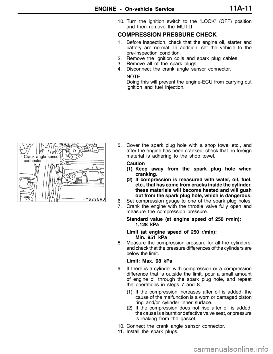
4. Disconnect the crank angle sensor connector.
NOTE
Doing this will prevent the engine-ECU from carrying out
ignition and fuel injection.
5. Cover the spark plug hole with a shop towel etc., and
after the engine has been cranked, check that no foreign
material is adhering to the shop towel.
Caution
(1) Keep away from the spark plug hole when
cranking.
(2) If compression is measured with water, oil, fuel,
etc., that has come from cracks inside the cylinder,
these materials will become heated and will gush
out from the spark plug hole, which is dangerous.
6. Set compression gauge to one of the spark plug holes.
7. Crank the engine with the throttle valve fully open and
measure the compression pressure.
Standard value (at engine speed of 250 r/min):
1,128 kPa
Limit (at engine speed of 250 r/min):
Min. 951 kPa
8. Measure the compression pressure for all the cylinders,
and check that the pressure differences of the cylinders are
below the limit.
Limit: Max. 98 kPa
9. If there is a cylinder with compression or a compression
difference that is outside the limit, pour a small amount
of engine oil through the spark plug hole, and repeat
the operations in steps 7 and 8.
(1) If the compression increases after oil is added, the
cause of the malfunction is a worn or damaged piston
ring and/or cylinder inner surface.
(2) If the compression does not rise after oil is added,
the cause is a burnt or defective valve seat, or pressure
is leaking from the gasket.
10. Connect the crank angle sensor connector.
11. Install the spark plugs.
Crank angle sensor
connector
Page 428 of 1449
ENGINE -Camshaft and Camshaft Oil Seal11A-22
"FACAMSHAFT POSITION SENSOR SUPPORT
INSTALLATION
1. Remove sealant remained on the camshaft position
sensor support.
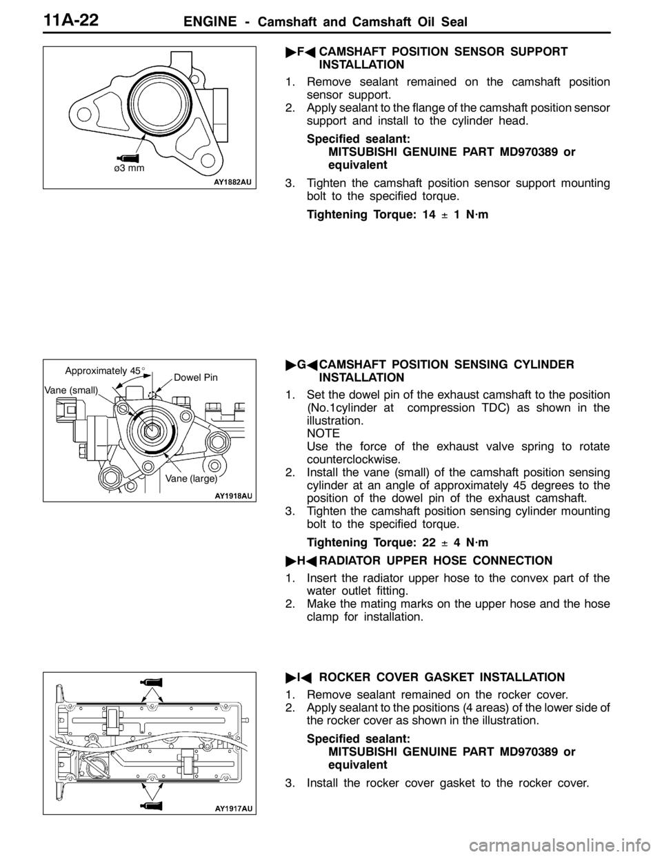
2. Apply sealant to the flange of the camshaft position sensor
support and install to the cylinder head.
Specified sealant:
MITSUBISHI GENUINE PART MD970389 or
equivalent
3. Tighten the camshaft position sensor support mounting
bolt to the specified torque.
Tightening Torque: 14±1 N·m
"GACAMSHAFT POSITION SENSING CYLINDER
INSTALLATION
1. Set the dowel pin of the exhaust camshaft to the position
(No.1cylinder at compression TDC) as shown in the
illustration.
NOTE
Use the force of the exhaust valve spring to rotate
counterclockwise.
2. Install the vane (small) of the camshaft position sensing
cylinder at an angle of approximately 45 degrees to the
position of the dowel pin of the exhaust camshaft.
3. Tighten the camshaft position sensing cylinder mounting
bolt to the specified torque.
Tightening Torque: 22±4 N·m
"HARADIATOR UPPER HOSE CONNECTION
1. Insert the radiator upper hose to the convex part of the
water outlet fitting.
2. Make the mating marks on the upper hose and the hose
clamp for installation.
"IAROCKER COVER GASKET INSTALLATION
1. Remove sealant remained on the rocker cover.
2. Apply sealant to the positions (4 areas) of the lower side of
the rocker cover as shown in the illustration.
Specified sealant:
MITSUBISHI GENUINE PART MD970389 or
equivalent
3. Install the rocker cover gasket to the rocker cover.
ø3 mm
Dowel Pin
Vane (small)
Approximately 45_
Vane (large)
Page 434 of 1449
ENGINE -Cylinder Head Gasket11A-28
CYLINDER HEAD GASKET
REMOVAL AND INSTALLATION
Caution
If the vehicle is equipped with the Brembo disc brake, during maintenance, take care not to contact
the parts or tools to the caliper because the paint of caliper will be scratched.
Pre-removal and Post-installation Operation
DFuel Outflow Preventive Operation (Refer to GROUP 13A - On-vehicle Service.)
DFuel Leak Check
DStrut Tower Bar Removal and Installation (Refer to GROUP 42.)
DUnder Cover Removal and Installation (Refer to GROUP 51 - Front Bumper.)
DDrive Belt Tension Check (Refer to P.11A-7.)
DAccelerator Cable Adjustment (Refer to GROUP 17 - On-vehicle Service.)
DDrainage and Refilling Engine Oil (Refer to GROUP 12 - On-vehicle Service.)
DDrainage and Refilling of Engine Coolant (Refer to GROUP 14 - On-vehicle Service.)
DAir Cleaner Assembly Removal and Installation (Refer to GROUP 15.)
DAir Hose E, Air Pipe C, Air hose D Removal and Installation (Refer to GROUP 15 - Intercooler.)
DBattery Removal and Installation
DCenter Cover Removal and Installation (Refer to P.11A-17.)
DAccelerator Cable Removal and Installation (Refer to GROUP 17.)
DRadiator Removal and Installation (Refer to GROUP 14.)
DSecondary Air Control Valve Bracket Removal and Installation (Refer to GROUP 15 - Secondary Air Supply System.)
DCrossmember Bar Removal and Installation (Refer to GROUP32 - Engine Roll Stopper, Centermember.)
DFront Exhaust Pipe Removal and Installation (Refer to GROUP 15.)
DStarter Removal and Installation (Refer to GROUP 16.)
DTiming Belt Removal and Installation (Refer to P.11A-34.)
Page 435 of 1449
ENGINE -Cylinder Head Gasket11A-29
5.0±1.0 N·m
61
2
3 4
57
8
910
11 12
1314
13±1 N·m
15
16
17
5.0±1.0 N·m
1819
9.0±1.0 N·m
9.0±1.0 N·m
(Engine oil)
1
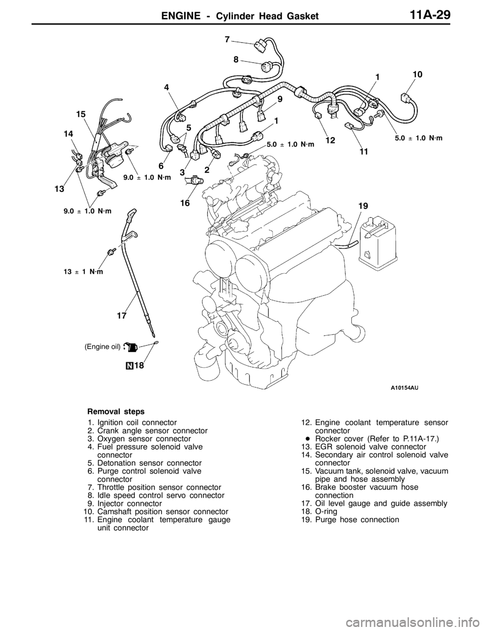
Removal steps
1. Ignition coil connector
2. Crank angle sensor connector
3. Oxygen sensor connector
4. Fuel pressure solenoid valve
connector
5. Detonation sensor connector
6. Purge control solenoid valve
connector
7. Throttle position sensor connector
8. Idle speed control servo connector
9. Injector connector
10. Camshaft position sensor connector
11. Engine coolant temperature gauge
unit connector12. Engine coolant temperature sensor
connector
DRocker cover (Refer to P.11A-17.)
13. EGR solenoid valve connector
14. Secondary air control solenoid valve
connector
15. Vacuum tank, solenoid valve, vacuum
pipe and hose assembly
16. Brake booster vacuum hose
connection
17. Oil level gauge and guide assembly
18. O-ring
19. Purge hose connection
Page 459 of 1449
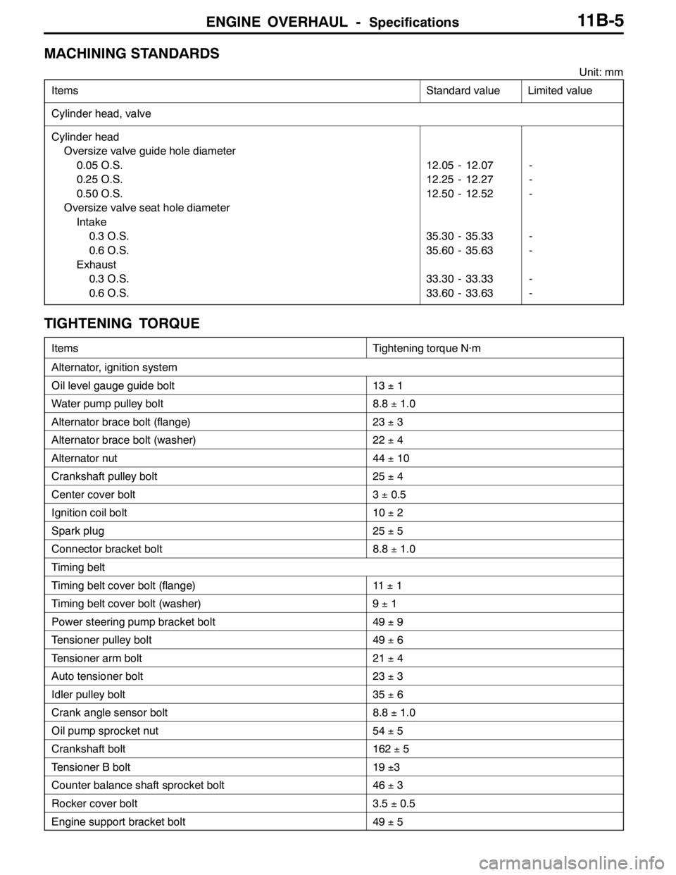
ENGINE OVERHAUL -Specifications11B-5
MACHINING STANDARDS
Unit: mm
Items
Standard valueLimited value
Cylinder head, valve
Cylinder head
Oversize valve guide hole diameter
0.05 O.S.
0.25 O.S.
0.50 O.S.
Oversize valve seat hole diameter
Intake
0.3 O.S.
0.6 O.S.
Exhaust
0.3 O.S.
0.6 O.S.
12.05 - 12.07
12.25 - 12.27
12.50 - 12.52
35.30 - 35.33
35.60 - 35.63
33.30 - 33.33
33.60 - 33.63-
-
-
-
-
-
-
TIGHTENING TORQUE
ItemsTightening torque N·m
Alternator, ignition system
Oil level gauge guide bolt13±1
Water pump pulley bolt8.8±1.0
Alternator brace bolt (flange)23±3
Alternator brace bolt (washer)22±4
Alternator nut44±10
Crankshaft pulley bolt25±4
Center cover bolt3±0.5
Ignition coil bolt10±2
Spark plug25±5
Connector bracket bolt8.8±1.0
Timing belt
Timing belt cover bolt (flange)11±1
Timing belt cover bolt (washer)9±1
Power steering pump bracket bolt49±9
Tensioner pulley bolt49±6
Tensioner arm bolt21±4
Auto tensioner bolt23±3
Idler pulley bolt35±6
Crank angle sensor bolt8.8±1.0
Oil pump sprocket nut54±5
Crankshaft bolt162±5
Tensioner B bolt19±3
Counter balance shaft sprocket bolt46±3
Rocker cover bolt3.5±0.5
Engine support bracket bolt49±5
Page 461 of 1449
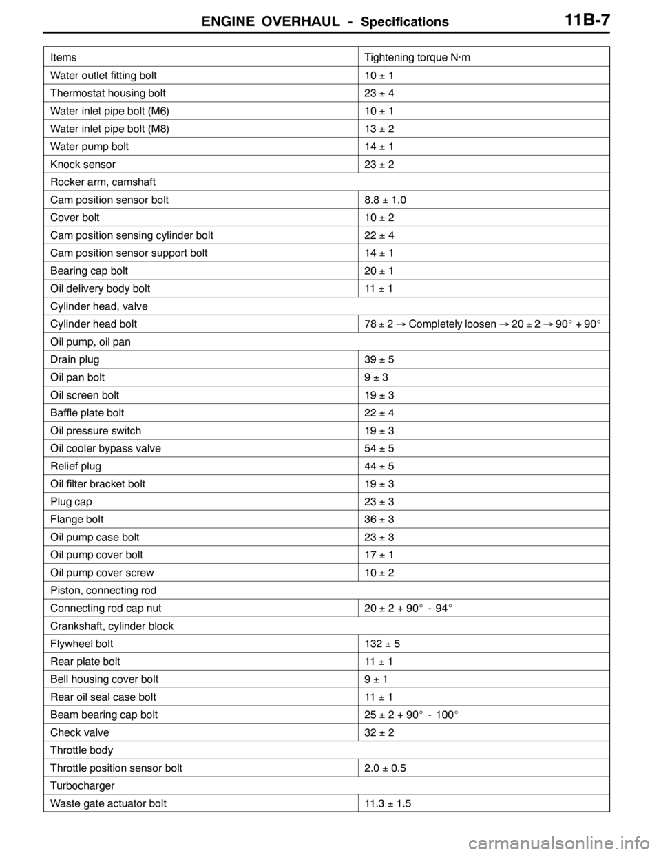
ENGINE OVERHAUL -Specifications11B-7
Items Tightening torque N·m
Water outlet fitting bolt10±1
Thermostat housing bolt23±4
Water inlet pipe bolt (M6)10±1
Water inlet pipe bolt (M8)13±2
Water pump bolt14±1
Knock sensor23±2
Rocker arm, camshaft
Cam position sensor bolt8.8±1.0
Cover bolt10±2
Cam position sensing cylinder bolt22±4
Cam position sensor support bolt14±1
Bearing cap bolt20±1
Oil delivery body bolt11±1
Cylinder head, valve
Cylinder head bolt78±2→Completely loosen→20±2→90_+90_
Oil pump, oil pan
Drain plug39±5
Oil pan bolt9±3
Oil screen bolt19±3
Baffle plate bolt22±4
Oil pressure switch19±3
Oil cooler bypass valve54±5
Relief plug44±5
Oil filter bracket bolt19±3
Plug cap23±3
Flange bolt36±3
Oil pump case bolt23±3
Oil pump cover bolt17±1
Oil pump cover screw10±2
Piston, connecting rod
Connecting rod cap nut20±2+90_-94_
Crankshaft, cylinder block
Flywheel bolt132±5
Rear plate bolt11±1
Bell housing cover bolt9±1
Rear oil seal case bolt11±1
Beam bearing cap bolt25±2+90_- 100_
Check valve32±2
Throttle body
Throttle position sensor bolt2.0±0.5
Turbocharger
Waste gate actuator bolt11.3±1.5
Page 467 of 1449
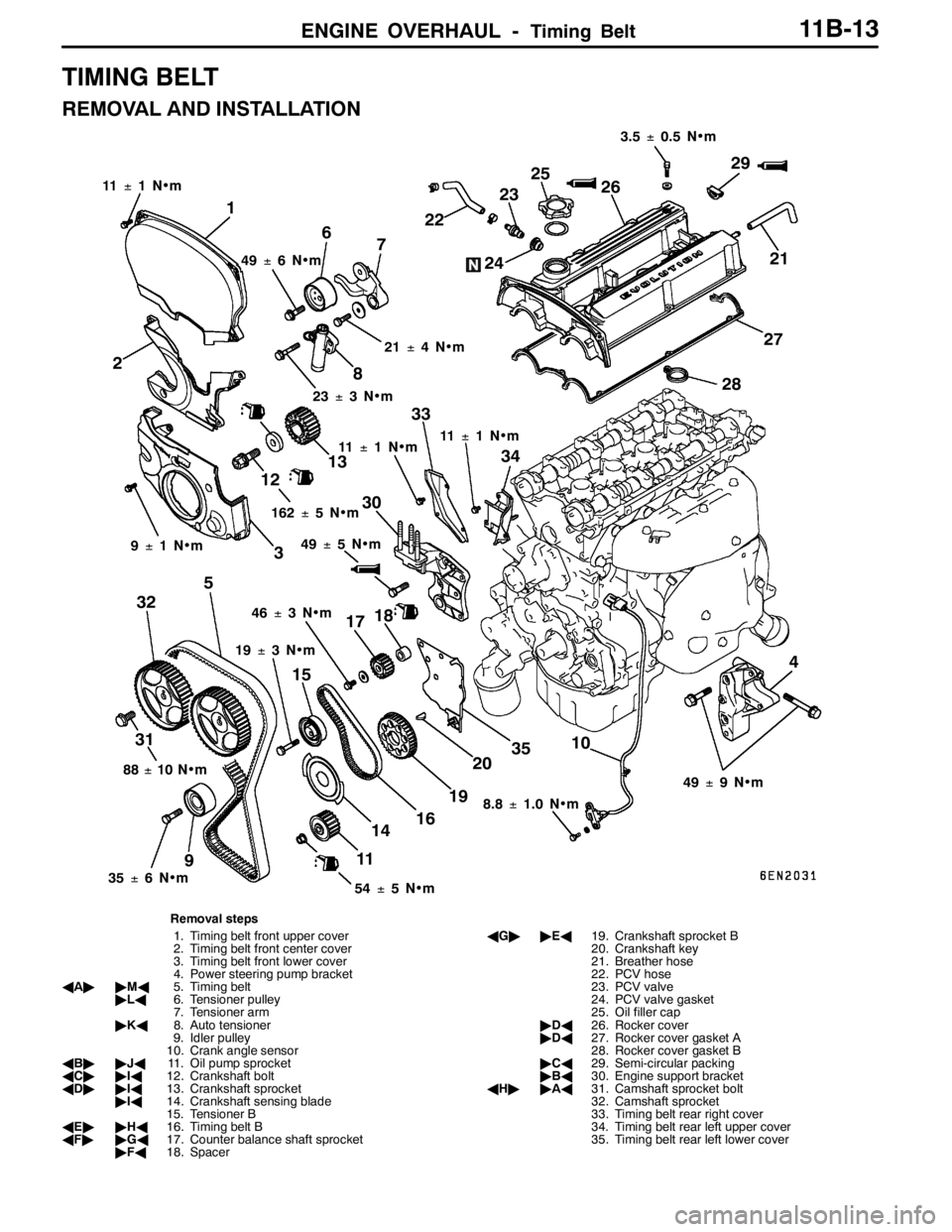
ENGINE OVERHAUL -Timing Belt11B-13
TIMING BELT
REMOVAL AND INSTALLATION
1
11±1N•m
2
3
4 56
7
8
910
11 1213
14 15
16 1718
192021 2223
2425
26
27
2829
30
313233
34
35
49±6N•m
21±4N•m
23±3N•m
11±1N•m11±1N•m
88±10 N•m
35±6N•m
54±5N•m 19±3N•m 46±3N•m 9±1N•m162±5N•m3.5±0.5 N•m
49±9N•m
8.8±1.0 N•m 49±5N•m
Removal steps
1. Timing belt front upper cover
2. Timing belt front center cover
3. Timing belt front lower cover
4. Power steering pump bracket
AA""MA5. Timing belt
"LA6. Tensioner pulley
7. Tensioner arm
"KA8. Auto tensioner
9. Idler pulley
10. Crank angle sensor
AB""JA11. Oil pump sprocket
AC""IA12. Crankshaft bolt
AD""IA13. Crankshaft sprocket
"IA14. Crankshaft sensing blade
15. Tensioner B
AE""HA16. Timing belt B
AF""GA17. Counter balance shaft sprocket
"FA18. SpacerAG""EA19. Crankshaft sprocket B
20. Crankshaft key
21. Breather hose
22. PCV hose
23. PCV valve
24. PCV valve gasket
25. Oil filler cap
"DA26. Rocker cover
"DA27. Rocker cover gasket A
28. Rocker cover gasket B
"CA29. Semi-circular packing
"BA30. Engine support bracket
AH""AA31. Camshaft sprocket bolt
32. Camshaft sprocket
33. Timing belt rear right cover
34. Timing belt rear left upper cover
35. Timing belt rear left lower cover
Page 474 of 1449
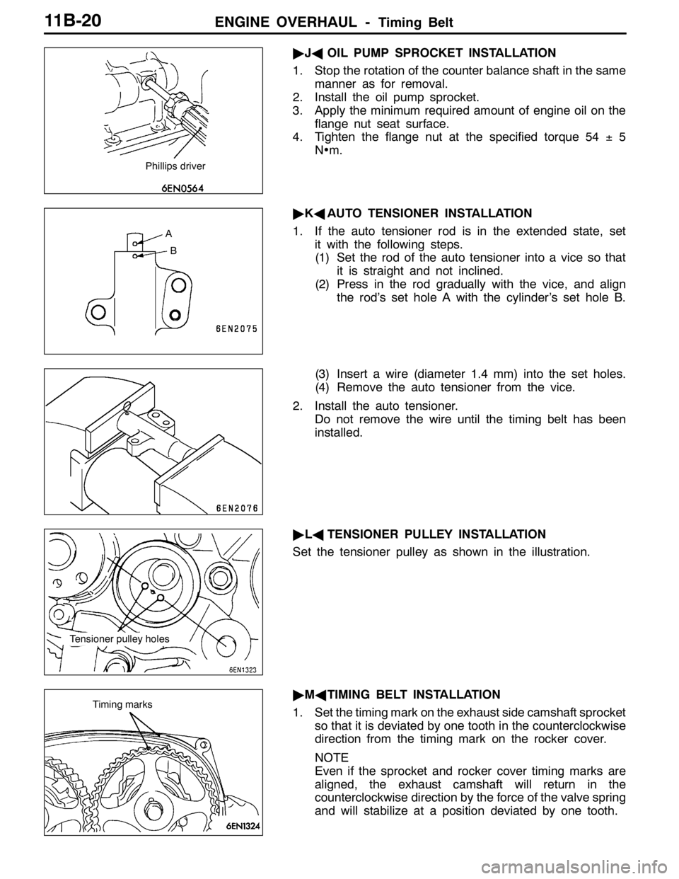
ENGINE OVERHAUL -Timing Belt11B-20
"JAOIL PUMP SPROCKET INSTALLATION
1. Stop the rotation of the counter balance shaft in the same
manner as for removal.
2. Install the oil pump sprocket.
3. Apply the minimum required amount of engine oil on the
flange nut seat surface.
4. Tighten the flange nut at the specified torque 54±5
N•m.
"KAAUTO TENSIONER INSTALLATION
1. If the auto tensioner rod is in the extended state, set
it with the following steps.
(1) Set the rod of the auto tensioner into a vice so that
it is straight and not inclined.
(2) Press in the rod gradually with the vice, and align
the rod’s set hole A with the cylinder’s set hole B.
(3) Insert a wire (diameter 1.4 mm) into the set holes.
(4) Remove the auto tensioner from the vice.
2. Install the auto tensioner.
Do not remove the wire until the timing belt has been
installed.
"LATENSIONER PULLEY INSTALLATION
Set the tensioner pulley as shown in the illustration.
"MATIMING BELT INSTALLATION
1. Set the timing mark on the exhaust side camshaft sprocket
so that it is deviated by one tooth in the counterclockwise
direction from the timing mark on the rocker cover.
NOTE
Even if the sprocket and rocker cover timing marks are
aligned, the exhaust camshaft will return in the
counterclockwise direction by the force of the valve spring
and will stabilize at a position deviated by one tooth.
Phillips driver
A
B
Tensioner pulley holes
Timing marks
Page 475 of 1449
ENGINE OVERHAUL -Timing Belt11B-21
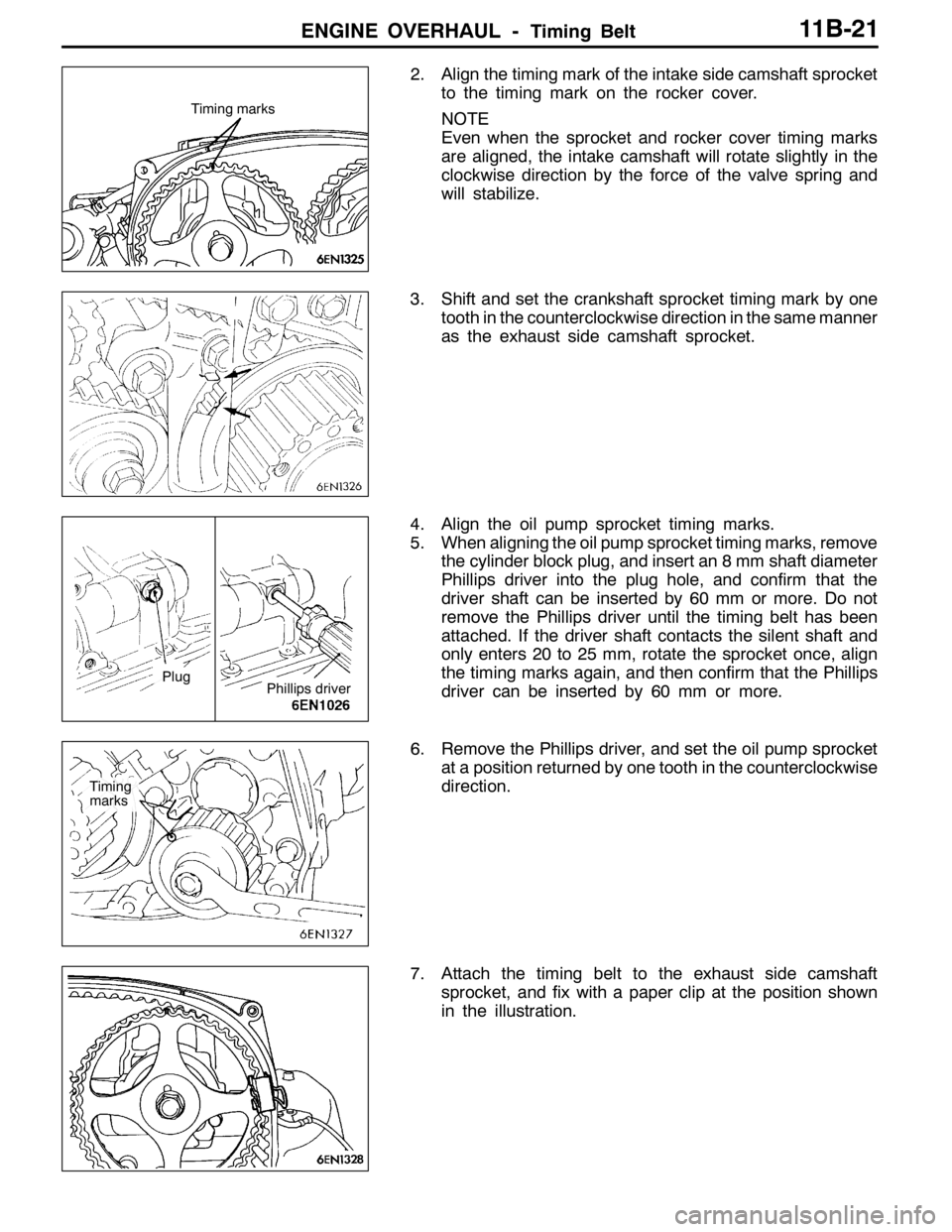
2. Align the timing mark of the intake side camshaft sprocket
to the timing mark on the rocker cover.
NOTE
Even when the sprocket and rocker cover timing marks
are aligned, the intake camshaft will rotate slightly in the
clockwise direction by the force of the valve spring and
will stabilize.
3. Shift and set the crankshaft sprocket timing mark by one
tooth in the counterclockwise direction in the same manner
as the exhaust side camshaft sprocket.
4. Align the oil pump sprocket timing marks.
5. When aligning the oil pump sprocket timing marks, remove
the cylinder block plug, and insert an 8 mm shaft diameter
Phillips driver into the plug hole, and confirm that the
driver shaft can be inserted by 60 mm or more. Do not
remove the Phillips driver until the timing belt has been
attached. If the driver shaft contacts the silent shaft and
only enters 20 to 25 mm, rotate the sprocket once, align
the timing marks again, and then confirm that the Phillips
driver can be inserted by 60 mm or more.
6. Remove the Phillips driver, and set the oil pump sprocket
at a position returned by one tooth in the counterclockwise
direction.
7. Attach the timing belt to the exhaust side camshaft
sprocket, and fix with a paper clip at the position shown
in the illustration.
Timing marks
Phillips driverPlug
Timing
marks
Page 501 of 1449
ENGINE OVERHAUL -Oil Pump and Oil Pan11B-47
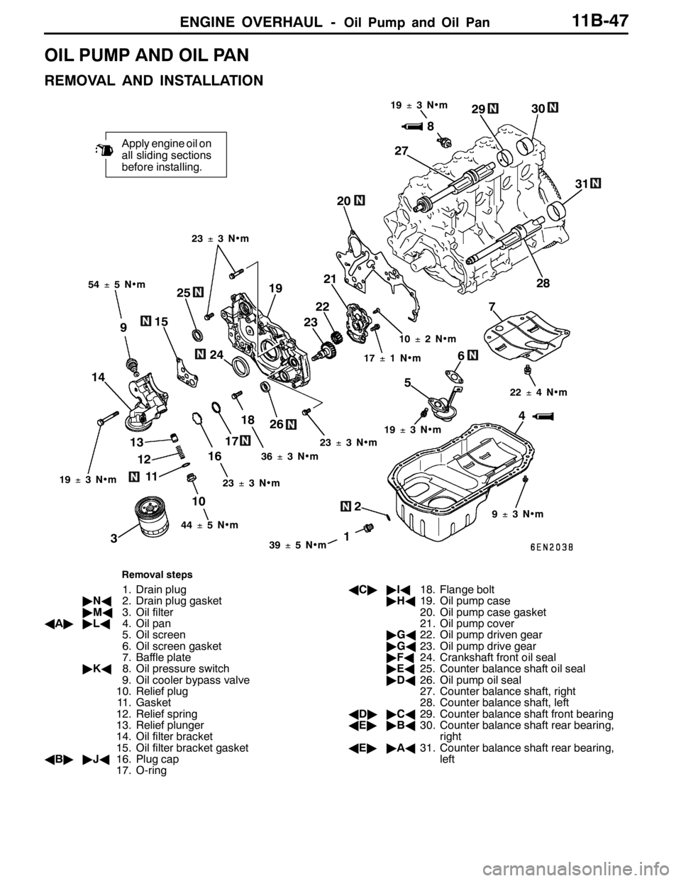
OIL PUMP AND OIL PAN
REMOVAL AND INSTALLATION
2
1
Apply engine oil on
all sliding sections
before installing.
4 56
12 13
16187 20
38
9
10 1415
1719
1139±5N•m 54±5N•m19±3N•m
36±3N•m23±3N•m 17±1N•m 10±2N•m
9±3N•m 22±4N•m 23±3N•m
19±3N•m
44±5N•m 23±3N•m
25
24232221
26272930
31
28
19±3N•m
Removal steps
1. Drain plug
"NA2. Drain plug gasket
"MA3. Oil filter
AA""LA4. Oil pan
5. Oil screen
6. Oil screen gasket
7. Baffle plate
"KA8. Oil pressure switch
9. Oil cooler bypass valve
10. Relief plug
11. Gasket
12. Relief spring
13. Relief plunger
14. Oil filter bracket
15. Oil filter bracket gasket
AB""JA16. Plug cap
17. O-ringAC""IA18. Flange bolt
"HA19. Oil pump case
20. Oil pump case gasket
21. Oil pump cover
"GA22. Oil pump driven gear
"GA23. Oil pump drive gear
"FA24. Crankshaft front oil seal
"EA25. Counter balance shaft oil seal
"DA26. Oil pump oil seal
27. Counter balance shaft, right
28. Counter balance shaft, left
AD""CA29. Counter balance shaft front bearing
AE""BA30. Counter balance shaft rear bearing,
right
AE""AA31. Counter balance shaft rear bearing,
left