wheel bolt torque MITSUBISHI LANCER EVOLUTION 2007 Service Repair Manual
[x] Cancel search | Manufacturer: MITSUBISHI, Model Year: 2007, Model line: LANCER EVOLUTION, Model: MITSUBISHI LANCER EVOLUTION 2007Pages: 1449, PDF Size: 56.82 MB
Page 433 of 1449
ENGINE -Crankshaft Oil Seal11A-27
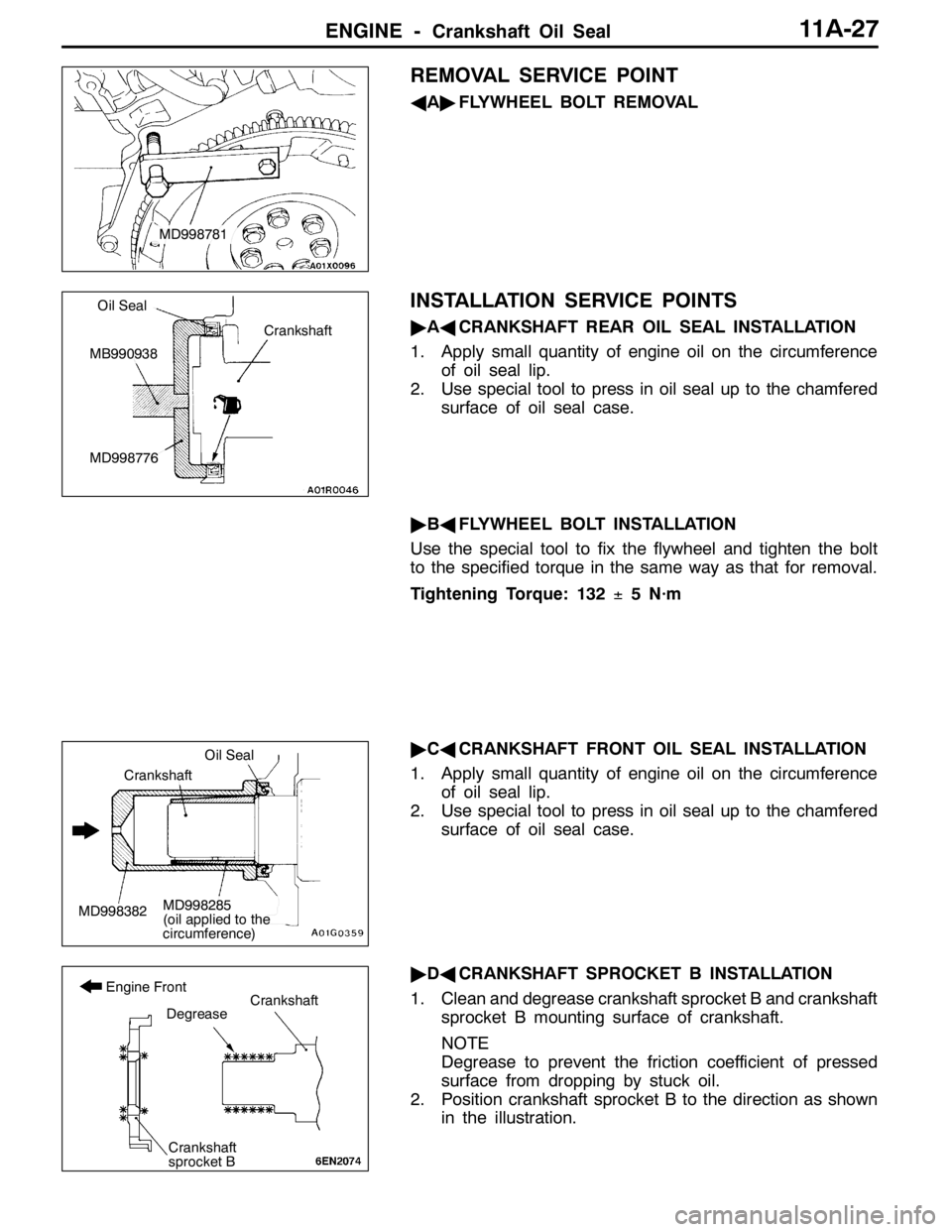
REMOVAL SERVICE POINT
AA"FLYWHEEL BOLT REMOVAL
INSTALLATION SERVICE POINTS
"AACRANKSHAFT REAR OIL SEAL INSTALLATION
1. Apply small quantity of engine oil on the circumference
of oil seal lip.
2. Use special tool to press in oil seal up to the chamfered
surface of oil seal case.
"BAFLYWHEEL BOLT INSTALLATION
Use the special tool to fix the flywheel and tighten the bolt
to the specified torque in the same way as that for removal.
Tightening Torque: 132±5 N·m
"CACRANKSHAFT FRONT OIL SEAL INSTALLATION
1. Apply small quantity of engine oil on the circumference
of oil seal lip.
2. Use special tool to press in oil seal up to the chamfered
surface of oil seal case.
"DACRANKSHAFT SPROCKET B INSTALLATION
1. Clean and degrease crankshaft sprocket B and crankshaft
sprocket B mounting surface of crankshaft.
NOTE
Degrease to prevent the friction coefficient of pressed
surface from dropping by stuck oil.
2. Position crankshaft sprocket B to the direction as shown
in the illustration.
MD998781
Crankshaft
Oil Seal
MB990938
MD998776
MD998382
Oil Seal
Crankshaft
MD998285
(oil applied to the
circumference)
Crankshaft
sprocket B
Degrease
Engine FrontCrankshaft
Page 461 of 1449

ENGINE OVERHAUL -Specifications11B-7
Items Tightening torque N·m
Water outlet fitting bolt10±1
Thermostat housing bolt23±4
Water inlet pipe bolt (M6)10±1
Water inlet pipe bolt (M8)13±2
Water pump bolt14±1
Knock sensor23±2
Rocker arm, camshaft
Cam position sensor bolt8.8±1.0
Cover bolt10±2
Cam position sensing cylinder bolt22±4
Cam position sensor support bolt14±1
Bearing cap bolt20±1
Oil delivery body bolt11±1
Cylinder head, valve
Cylinder head bolt78±2→Completely loosen→20±2→90_+90_
Oil pump, oil pan
Drain plug39±5
Oil pan bolt9±3
Oil screen bolt19±3
Baffle plate bolt22±4
Oil pressure switch19±3
Oil cooler bypass valve54±5
Relief plug44±5
Oil filter bracket bolt19±3
Plug cap23±3
Flange bolt36±3
Oil pump case bolt23±3
Oil pump cover bolt17±1
Oil pump cover screw10±2
Piston, connecting rod
Connecting rod cap nut20±2+90_-94_
Crankshaft, cylinder block
Flywheel bolt132±5
Rear plate bolt11±1
Bell housing cover bolt9±1
Rear oil seal case bolt11±1
Beam bearing cap bolt25±2+90_- 100_
Check valve32±2
Throttle body
Throttle position sensor bolt2.0±0.5
Turbocharger
Waste gate actuator bolt11.3±1.5
Page 473 of 1449
ENGINE OVERHAUL -Timing Belt11B-19
Caution
(1) Measure when the belt’s surface temperature is
close to room temperature.
(2) Make sure that water or oil, etc., do not get on
the mike.
(3) If strong winds contact the mike or if noise is
generated in the area while measuring, a value
that differs from the actual value may be indicated.
(4) If the measurement is carried out with the mike
contacted against the belt, a value that differs
from the actual value may be indicated.
(5) Do not measure while the engine is running.
11. Disconnect MUT-II.
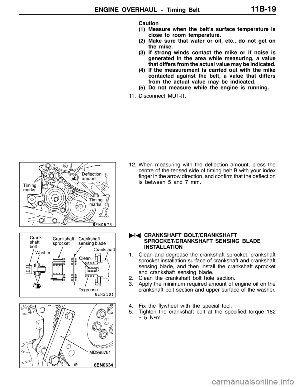
12. When measuring with the deflection amount, press the
centre of the tensed side of timing belt B with your index
finger in the arrow direction, and confirm that the deflection
is between 5 and 7 mm.
"IACRANKSHAFT BOLT/CRANKSHAFT
SPROCKET/CRANKSHAFT SENSING BLADE
INSTALLATION
1. Clean and degrease the crankshaft sprocket, crankshaft
sprocket installation surface of crankshaft and crankshaft
sensing blade, and then install the crankshaft sprocket
and crankshaft sensing blade.
2. Clean the crankshaft bolt hole section.
3. Apply the minimum required amount of engine oil on the
crankshaft bolt section and upper surface of the washer.
4. Fix the flywheel with the special tool.
5. Tighten the crankshaft bolt at the specified torque 162
±5N•m.
Timing
marks
Timing
marks
Deflection
amount
Crank-
shaft
bolt
WasherCrankshaft
sprocketCrankshaft
sensing blade
Crankshaft
Clean
Degrease
MD998781
Page 931 of 1449

FRONT AXLE -Service Specifications/Lubricants/Special Tools26-3
SERVICE SPECIFICATIONS
ItemStandard valueLimit
Wheel bearing axial play mm-0.06
WheelbearingrotationstartingtorqueN·m-103orlessWheelbearing rotation startingtorqueN·m-1.03orless
Setting of T.J. boot length mm85±3-
Opening dimension of the
special tool (MB991561) mmWhen the B.J.boot band
(small) is crimped.2.9-
When the B.J.boot band
(big) is crimped.3.2-
Crimped width of the B.J.boot band mm2.4 - 2.8-
LUBRICANTS
ItemsSpecified lubricantsQuantity g
T.J. boot greaseRepair kit grease120±10
B.J.boot greaseRepair kit grease11 0±10
SPECIAL TOOLS
ToolNumberNameUse
MB990767End yoke holderFixing of the hub
MB991618Hub bolt removerRemoval of the hub bolt
MB991113 or
MB990635Steering linkage
pullerDisconnection of ball joint
A
B
MB990241
A: MB990242
B: MB990244Axle shaft puller
A: Puller shaft
B: Puller barDRemoval of the drive shaft
DRemoval of the hub
MB991354Puller bodyDRemoval of the drive shaft
DRemoval of the hub
Page 936 of 1449
FRONT AXLE -Hub and Knuckle Assembly26-8
INSTALLATION SERVICE POINT
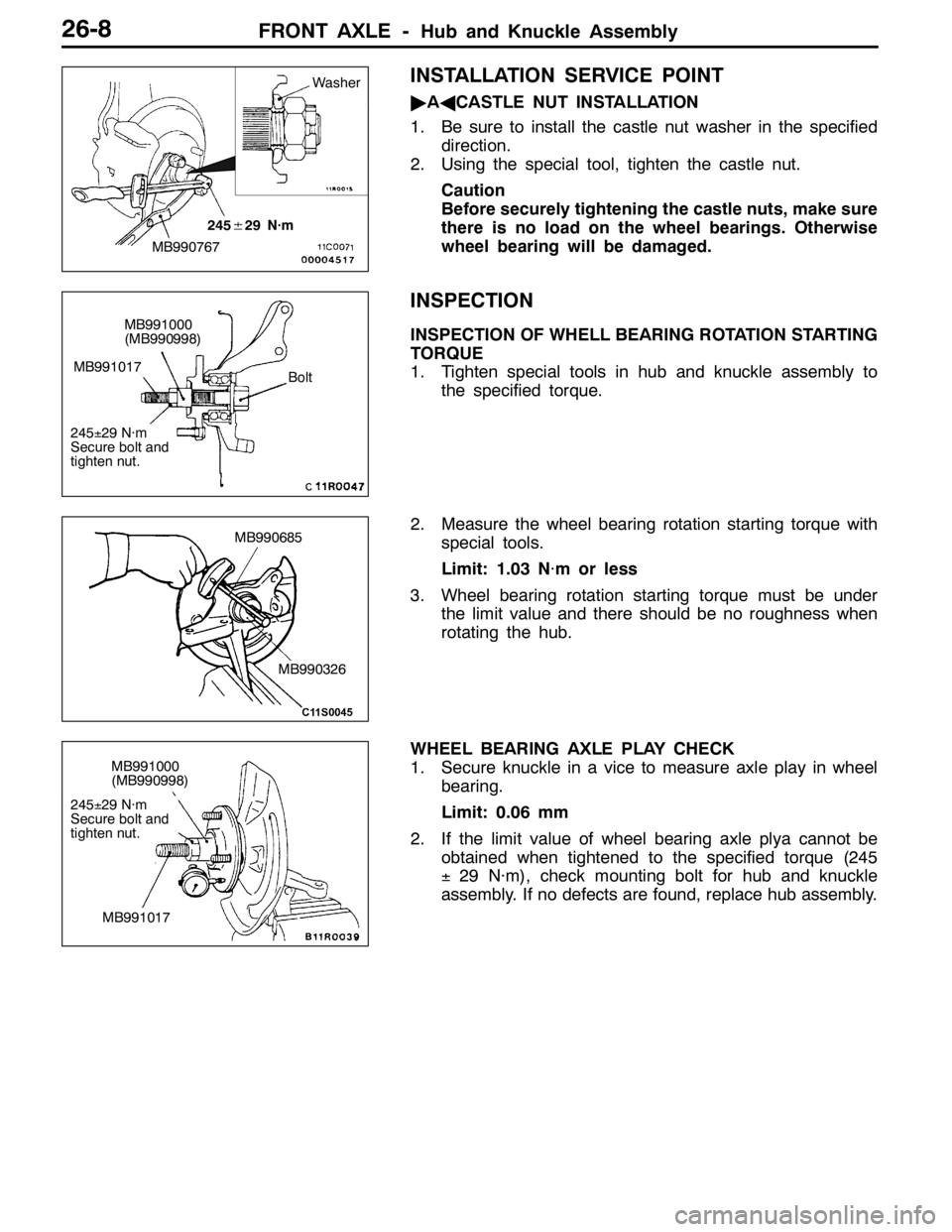
"AACASTLE NUT INSTALLATION
1. Be sure to install the castle nut washer in the specified
direction.
2. Using the special tool, tighten the castle nut.
Caution
Before securely tightening the castle nuts, make sure
there is no load on the wheel bearings. Otherwise
wheel bearing will be damaged.
INSPECTION
INSPECTION OF WHELL BEARING ROTATION STARTING
TORQUE
1. Tighten special tools in hub and knuckle assembly to
the specified torque.
2. Measure the wheel bearing rotation starting torque with
special tools.
Limit: 1.03 N·m or less
3. Wheel bearing rotation starting torque must be under
the limit value and there should be no roughness when
rotating the hub.
WHEEL BEARING AXLE PLAY CHECK
1. Secure knuckle in a vice to measure axle play in wheel
bearing.
Limit: 0.06 mm
2. If the limit value of wheel bearing axle plya cannot be
obtained when tightened to the specified torque (245
±29 N·m), check mounting bolt for hub and knuckle
assembly. If no defects are found, replace hub assembly.
MB990767
245±29 N·m
Washer
MB991000
(MB990998)
Bolt
245±29 N·m
Secure bolt and
tighten nut.
MB991017
MB990326
MB990685
MB991000
(MB990998)
245±29 N·m
Secure bolt and
tighten nut.
MB991017
Page 968 of 1449

REAR AXLE -On-vehicle Service27B-22
8. If the measured value exceeds the standard value, replace
the hydraulic unit.
9. Connect the hydraulic unit and the hydraulic unit hose
assembly, and connect the torque transfer differential and
hydraulic unit hose assembly, tighten the flare nut in
specified torque.
Tightening torque: 34±5 N·m (Thread is not lubricated)
26±4 N·m (Thread is lubricated)
10. Supply the specified fluid up to the MAX level of the
oil reservoir, and bleed.
Specified fluid: ATF-SP III
Quantity: 1 L
WHEEL BEARING AXIAL PLAY CHECK
1. Remove the brake caliper and brake disc.
2. Check the bearing’s axial play.
Place a dial gauge against the hub surface; then move
the hub in the axial direction and check whether or not
there is axial play.
Limit: 0.05 mm
3. If the axial play exceeds the limit, the castle nut should
be tightened to the specified torque 225±25 N·m and
check the axial play again.
4. Replace the rear hub assembly if an adjustment cannot
be made to within the limit.
WHEEL BEARING ROTARY-SLIDING
RESISTANCE CHECK
1. Remove the brake caliper and brake disc.
2. After turning the hub a few times to seat the bearing,
wind a rope around the hub bolt and turn the hub by
pulling at a 90_angle with a spring balance. Measure
to determine whether or not the rotary-sliding resistance
of the rear hub is at the limit value.
Limit: 22 N or less
Page 969 of 1449
REAR AXLE -On-vehicle Service27B-23
3. If the limit value is exceeded, loosen the flange nut and
then tighten it to the specified torque 225±25 N·m and
check the rear hub rotary sliding resistance again.
4. Replace the rear hub assembly if an adjustment cannot
be made to within the limit.
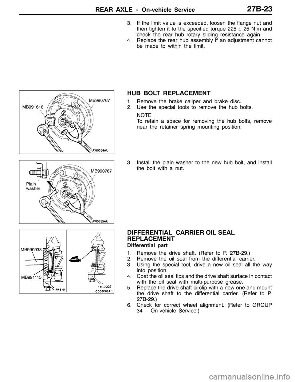
HUB BOLT REPLACEMENT
1. Remove the brake caliper and brake disc.
2. Use the special tools to remove the hub bolts.
NOTE
To retain a space for removing the hub bolts, remove
near the retainer spring mounting position.
3. Install the plain washer to the new hub bolt, and install
the bolt with a nut.
DIFFERENTIAL CARRIER OIL SEAL
REPLACEMENT
Differential part
1. Remove the drive shaft. (Refer to P. 27B-29.)
2. Remove the oil seal from the differential carrier.
3. Using the special tool, drive a new oil seal all the way
into position.
4. Coat the oil seal lips and the drive shaft surface in contact
with the oil seal with multi-purpose grease.
5. Replace the drive shaft circlip with a new one and mount
the drive shaft to the differential carrier. (Refer to P.
27B-29.)
6. Check for correct wheel alignment. (Refer to GROUP
34 – On-vehicle Service.)
MB991618MB990767
Plain
washerMB990767
MB990938
MB991115
Page 1031 of 1449
FRONT SUSPENSION -On-vehicle Service33A-5
Tightening torque: 52±2 N·m
3. Confirm that the toe-in is at the standard value.
4. Use a turning radius gauge to check that the steering
angle is at the standard value.
Standard value:
Inner wheels31_45’±1_30’
Outer wheels (for reference)27_15’
TOE-OUT ANGLE ON TURNS
To check the steering linkage, especially after the vehicle
has been involved in an accident or if an accident is presumed,
it is advisable to check the toe-out angle on turns in addition
to the wheel alignment.
Conduct this test on the left turn as well as on the right turn.
Standard value:
ItemsSpecifications
Toe-out angle on turns
(inner wheel when outer wheel at 20_)22_00’±1_30’
CAMBER, CASTER AND KINGPIN INCLINATION
Standard value:
ItemsSpecifications
Camber
(Selectable from 2 options)-1_00’±30’* or - 2_00’±30’*
Caster3_55’±30’*
Kingpin inclination13_45’±1_30’
NOTE
1. *: difference between right and left wheels must be less
than 30’
2. Caster and kingpin inclination are preset at the factory
and cannot be adjusted.
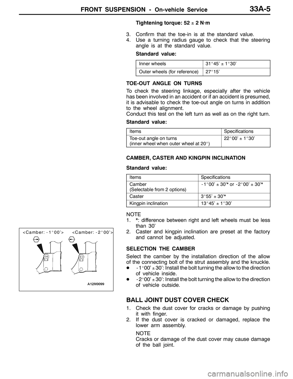
SELECTION THE CAMBER
Select the camber by the installation direction of the allow
of the connecting bolt of the strut assembly and the knuckle.
D-1
_00’±30’: Install the bolt turning the allow to the direction
of vehicle inside.
D-2
_00’±30’: Install the bolt turning the allow to the direction
of vehicle outside.
BALL JOINT DUST COVER CHECK
1. Check the dust cover for cracks or damage by pushing
it with finger.
2. If the dust cover is cracked or damaged, replace the
lower arm assembly.
NOTE
Cracks or damage of the dust cover may cause damage
of the ball joint.
Page 1056 of 1449
BASIC BRAKE SYSTEM -On-vehicle Service35A-14
BRAKE DISC THICKNESS CHECK
Caution: Brembo disc brake
Take care not to contact the parts or tools to the caliper
because the paint of caliper will be scratched. And if
there is brake fluid on the caliper, wipe out quickly.
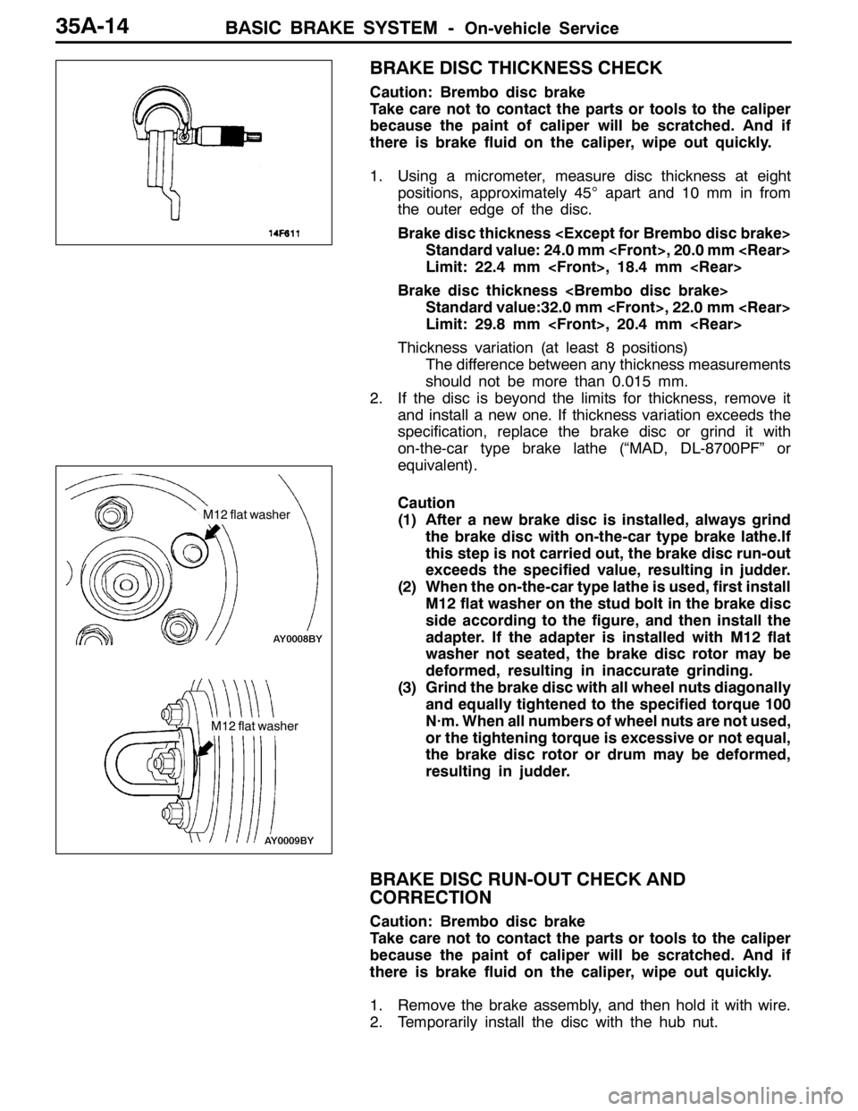
1. Using a micrometer, measure disc thickness at eight
positions, approximately 45°apart and 10 mm in from
the outer edge of the disc.
Brake disc thickness
Standard value: 24.0 mm
Limit: 22.4 mm
Brake disc thickness
Standard value:32.0 mm
Limit: 29.8 mm
Thickness variation (at least 8 positions)
The difference between any thickness measurements
should not be more than 0.015 mm.
2. If the disc is beyond the limits for thickness, remove it
and install a new one. If thickness variation exceeds the
specification, replace the brake disc or grind it with
on-the-car type brake lathe (“MAD, DL-8700PF” or
equivalent).
Caution
(1) After a new brake disc is installed, always grind
the brake disc with on-the-car type brake lathe.If
this step is not carried out, the brake disc run-out
exceeds the specified value, resulting in judder.
(2) When the on-the-car type lathe is used, first install
M12 flat washer on the stud bolt in the brake disc
side according to the figure, and then install the
adapter. If the adapter is installed with M12 flat
washer not seated, the brake disc rotor may be
deformed, resulting in inaccurate grinding.
(3) Grind the brake disc with all wheel nuts diagonally
and equally tightened to the specified torque 100
N·m. When all numbers of wheel nuts are not used,
or the tightening torque is excessive or not equal,
the brake disc rotor or drum may be deformed,
resulting in judder.
BRAKE DISC RUN-OUT CHECK AND
CORRECTION
Caution: Brembo disc brake
Take care not to contact the parts or tools to the caliper
because the paint of caliper will be scratched. And if
there is brake fluid on the caliper, wipe out quickly.
1. Remove the brake assembly, and then hold it with wire.
2. Temporarily install the disc with the hub nut.
M12 flat washer
M12 flat washer
Page 1057 of 1449
BASIC BRAKE SYSTEM -On-vehicle Service35A-15
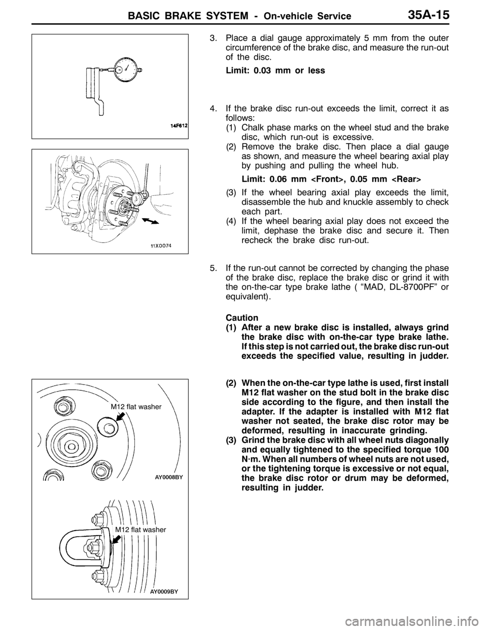
3. Place a dial gauge approximately 5 mm from the outer
circumference of the brake disc, and measure the run-out
of the disc.
Limit: 0.03 mm or less
4. If the brake disc run-out exceeds the limit, correct it as
follows:
(1) Chalk phase marks on the wheel stud and the brake
disc, which run-out is excessive.
(2) Remove the brake disc. Then place a dial gauge
as shown, and measure the wheel bearing axial play
by pushing and pulling the wheel hub.
Limit: 0.06 mm
(3) If the wheel bearing axial play exceeds the limit,
disassemble the hub and knuckle assembly to check
each part.
(4) If the wheel bearing axial play does not exceed the
limit, dephase the brake disc and secure it. Then
recheck the brake disc run-out.
5. If the run-out cannot be corrected by changing the phase
of the brake disc, replace the brake disc or grind it with
the on-the-car type brake lathe ( “MAD, DL-8700PF” or
equivalent).
Caution
(1) After a new brake disc is installed, always grind
the brake disc with on-the-car type brake lathe.
If this step is not carried out, the brake disc run-out
exceeds the specified value, resulting in judder.
(2) When the on-the-car type lathe is used, first install
M12 flat washer on the stud bolt in the brake disc
side according to the figure, and then install the
adapter. If the adapter is installed with M12 flat
washer not seated, the brake disc rotor may be
deformed, resulting in inaccurate grinding.
(3) Grind the brake disc with all wheel nuts diagonally
and equally tightened to the specified torque 100
N·m. When all numbers of wheel nuts are not used,
or the tightening torque is excessive or not equal,
the brake disc rotor or drum may be deformed,
resulting in judder.
M12 flat washer
M12 flat washer