change wheel MITSUBISHI LANCER EVOLUTION 2014 10.G Owners Manual
[x] Cancel search | Manufacturer: MITSUBISHI, Model Year: 2014, Model line: LANCER EVOLUTION, Model: MITSUBISHI LANCER EVOLUTION 2014 10.GPages: 338, PDF Size: 40.99 MB
Page 33 of 338
Seat belts 4-8 Seat and restraint systems
4
N00406201483
All seats are equipped with a seat belt which uses one combined lap-and-shoulder belt withan emergency locking retractor. This system is designed to provide both com- fort and safety. It permits full extension and automatic retraction of the belts during nor-mal vehicle operation. A sensing device inside the belt retractor is designed to lock the retractor in the event of a sudden change inthe vehicle’s motion.
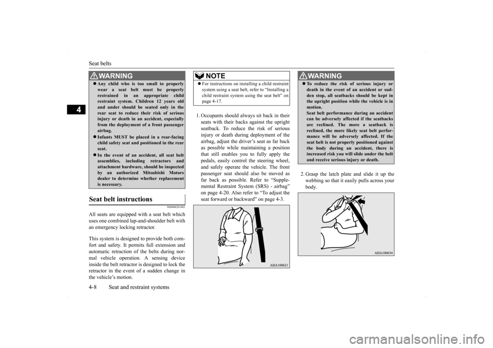
1. Occupants should always sit back in their seats with their backs against the upright seatback. To reduce the risk of seriousinjury or death during deployment of theairbag, adjust the driver’s seat as far back as possible while maintaining a position that still enables you to fully apply thepedals, easily control the steering wheel, and safely operate the vehicle. The front passenger seat should also be moved asfar back as possible. Refer to “Supple- mental Restraint System (SRS) - airbag” on page 4-20. Also refer to “To adjust theseat forward or backward” on page 4-3.
2. Grasp the latch plate and slide it up the webbing so that it easily pulls across yourbody.
Any child who is too small to properly wear a seat belt must be properly restrained in an appropriate child restraint system. Children 12 years old and under should be seated only in therear seat to reduce their risk of serious injury or death in an accident, especially from the deployment of a front passengerairbag. Infants MUST be placed in a rear-facing child safety seat and positioned in the rear seat. In the event of an accident, all seat belt assemblies, including retractors and attachment hardware, should be inspectedby an authorized Mitsubishi Motors dealer to determine whether replacement is necessary.
Seat belt instructions
WA R N I N G
NOTE
For instructions on installing a child restraint system using a seat belt, refer to “Installing a child restraint system using the seat belt” on page 4-17.
WA R N I N G To reduce the risk of serious injury or death in the event of an accident or sud- den stop, all seatbacks should be kept in the upright position while the vehicle is in motion.Seat belt performance during an accident can be adversely affected if the seatbacks are reclined. The more a seatback isreclined, the more likely seat belt perfor- mance will be adversely affected. If the seat belt is not properly positioned againstthe body during an accident, there is increased risk you will slide under the belt and receive serious injury or death.
BK0200800US.bo
ok 8 ページ 2013年2月14日 木曜日 午後2時28分
Page 112 of 338
Ignition switch
Features and controls 5-51
5
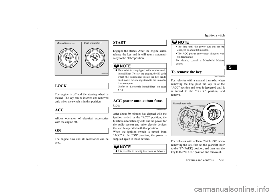
The engine is off and the steering wheel is locked. The key can be inserted and removedonly when the switch is in this position. Allows operation of electrical accessories with the engine off. The engine runs and all accessories can be used.
Engages the starter. After the engine starts, release the key and it will return automati-cally to the “ON” position.
N00539601101
After about 30 minutes has elapsed with theignition switch in the “ACC” position, the function automatically cuts out the power for the audio system and other electric devicesthat can be operated with that position. When the ignition switch is turned from “ACC” to the “ON” position, the power issupplied again to those devices.
N00550900139
For vehicles with a manual transaxle, whenremoving the key, push the key in at the“ACC” position and keep it depressed until it is turned to the “LOCK” position, and remove. For vehicles with a Twin Clutch SST, when removing the key, first set the gearshift leverto the “P” (PARK) position, and then turn the key to the “LOCK” position and remove it.
LOCK ACC ON Manual transaxle
Twin Clutch SST
START
NOTE
Your vehicle is equipped with an electronic immobilizer. To start the engine, the ID code which the transponder inside the key sendsmust match the one registered to the immobi- lizer computer. (Refer to “Electronic immobilizer” on page5-4.)
ACC power auto-cutout func- tion
NOTE
It is possible to modify functions as follows:
• The time until the power cuts out can be changed to about 60 minutes. • The ACC power auto-cutout function can be deactivated. For details, consult a Mitsubishi Motors dealer.
To remove the key
NOTE
Manual transaxle
BK0200800US.bo
ok 51 ページ 2013年2月14日 木曜日 午後2時28分
Page 125 of 338
Twin Clutch SST (Sportronic Shif
t Transmission) (if so equipped)
5-64 Features and controls
5
N00540300013
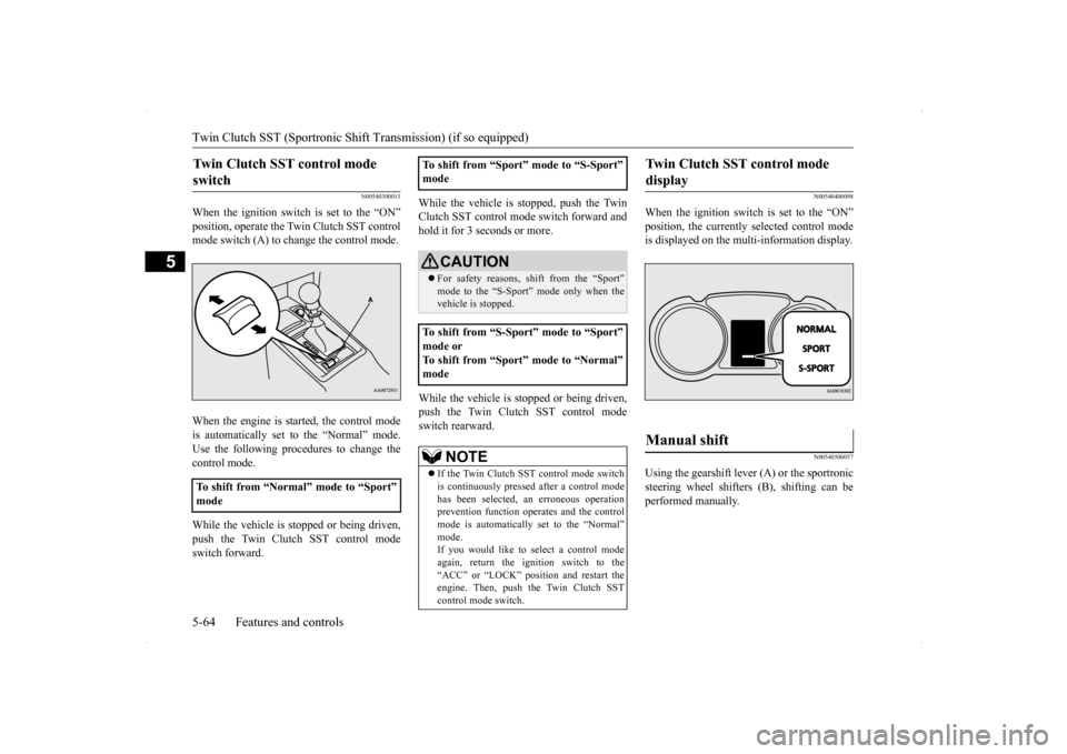
When the ignition switch is set to the “ON” position, operate the Twin Clutch SST control mode switch (A) to change the control mode. When the engine is started, the control mode is automatically set to the “Normal” mode. Use the following procedures to change the control mode. While the vehicle is stopped or being driven, push the Twin Clutch SST control modeswitch forward.
While the vehicle is stopped, push the Twin Clutch SST control mode switch forward and hold it for 3 seconds or more. While the vehicle is stopped or being driven, push the Twin Clutch SST control modeswitch rearward.
N00540400098
When the ignition switch is set to the “ON” position, the currently selected control mode is displayed on the multi-information display.
N00540500057
Using the gearshift lever (A) or the sportronic steering wheel shifters (B), shifting can be performed manually.
Twin Clutch SST control mode switch
To shift from “Normal” mode to “Sport” mode
To shift from “Sport” mode to “S-Sport” mode
CAUTION For safety reasons, shift from the “Sport” mode to the “S-Sport”
mode only when the
vehicle is stopped.
To shift from “S-Sport” mode to “Sport” mode or To shift from “Sport” mode to “Normal” mode
NOTE
If the Twin Clutch SST control mode switch is continuously pressed after a control mode has been selected, an erroneous operation prevention function operates and the control mode is automatically set to the “Normal” mode.If you would like to select a control mode again, return the ignition switch to the “ACC” or “LOCK” position and restart theengine. Then, push the Twin Clutch SST control mode switch.
Twin Clutch SST control mode display
Manual shift
BK0200800US.bo
ok 64 ページ 2013年2月14日 木曜日 午後2時28分
Page 126 of 338
Twin Clutch SST (Sportronic Shif
t Transmission) (if so equipped) Features and controls 5-65
5
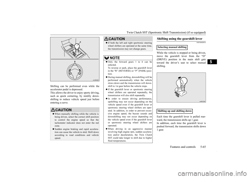
Shifting can be performed even while the accelerator pedal is depressed. This allows the driver to enjoy sporty driving,such as quick cornering, by nimbly down- shifting to reduce vehicle speed just before entering a curve.
N00540600016
While the vehicle is stopped or being driven, move the gearshift lever from the “D” (DRIVE) position in the main shift gatetoward the driver’s seat to select manual shifting. Each time the gearshift lever is pulled rear- ward, the transmission shifts up 1 gear.In addition, each time the gearshift lever is pushed forward, the transmission shifts down 1 gear.
CAUTION When manually shifting while the vehicle is being driven, select the correct shift positionto control the engine speed so that the tachometer indicator does not enter the red zone. Sudden engine braking and rapid accelera- tion can cause the vehicle to skid. Shift downaccording to road conditions and vehicle speed.
If both the left and right sportronic steering wheel shifters are operated at the same time, the transmission may not change gears.NOTE
Only the forward gears 1 to 6 can be selected. To reverse or park, place the gearshift leverin the “R” (REVERSE) or “P” (PARK) posi- tion. During manual shifting, downshifting will be performed automatically when the vehicle slows down and the transmission will down-shift to 1st gear before the vehicle stops. If the gearshift lever or sportronic steering wheel shifters are operated repeatedly, the transmission will also shift repeatedly. In order to ensure driving performance, upshifting may not occur depending on the vehicle speed even if the gearshift lever orsportronic steering wheel shifters are oper- ated. In addition, in order to prevent exces- sive engine speed, the buzzer sounds anddownshifting may not occur depending on the vehicle speed even if the gearshift lever or sportronic steering wheel shifters are operated. When driving in an aggressive manner involving high engine rpm, sudden accelera- tion and/or deceleration, the Twin ClutchSST could take longer to shift due to higher fluid temperatures.CAUTION
Shifting using the gearshift lever
Selecting manual shifting Shifting up and shifting down�ç
BK0200800US.bo
ok 65 ページ 2013年2月14日 木曜日 午後2時28分
Page 133 of 338
S-AWC (Super-All Wheel Control) 5-72 Features and controls
5
and power drive distribution of the center dif- ferential.
N00541500012
The AYC is a system, with a left-right differ-ential limiting function and yaw control func-tion, that enhances cornering performance and stability during
cornering by controlling
the left-right drive power difference of therear wheels, the braking force of all four wheels, and the vehicle yaw moment.
The left-right differential limiting function is a function that enhances driving performance and vehicle stability by preventing idle spin-ning of a wheel when driving on slippery road surfaces or when the road surfaces of the left and right wheels are different. The yaw control function is a function that enhances vehicle cornering performance by controlling the drive power difference of theleft and right wheels
and the braking force
when the vehicle does not turn in response to steering input, such as when the steeringwheel is turned quickly or when driving on slippery road surfaces.
N00542401057
Select the control mode from the followingthree types to suit the driving conditions.
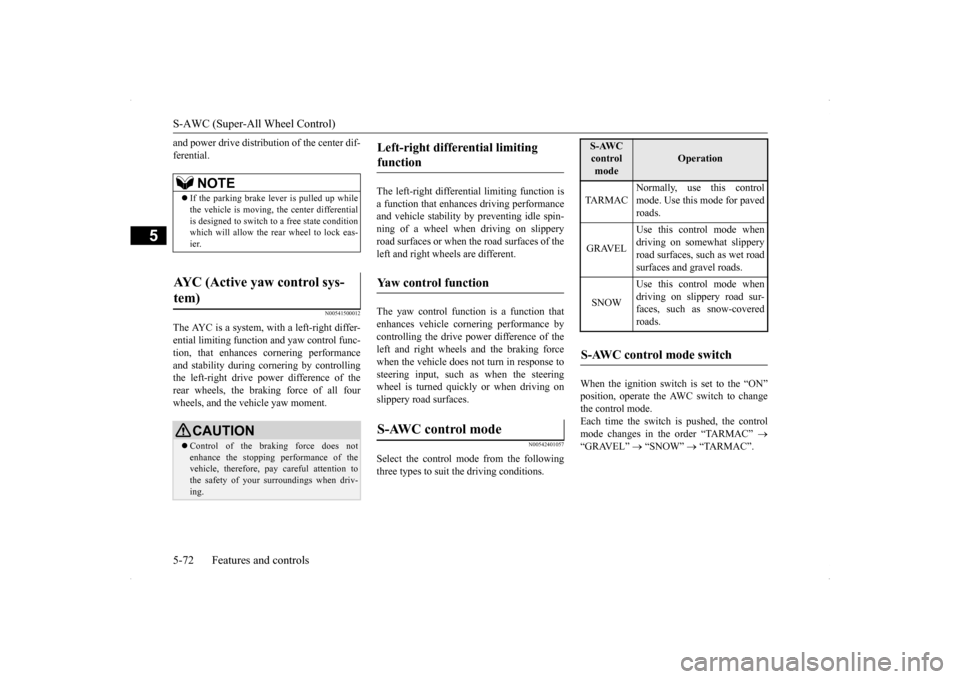
When the ignition switch is set to the “ON” position, operate the AWC switch to change the control mode.Each time the switch is pushed, the control mode changes in the order “TARMAC”
“GRAVEL”
“SNOW”
“TARMAC”.
NOTE
If the parking brake lever is pulled up while the vehicle is moving, the center differential is designed to switch to a free state conditionwhich will allow the rear wheel to lock eas- ier.
AYC (Active yaw control sys- tem)
CAUTION Control of the braking force does not enhance the stopping performance of the vehicle, therefore, pay careful attention to the safety of your surroundings when driv-ing.
Left-right differential limiting function Yaw control function S-AWC control mode
S-AWC control mode
Operation
TA R M A C
Normally, use this control mode. Use this mode for paved roads.
GRAVEL
Use this control mode when driving on somewhat slipperyroad surfaces, such as wet road surfaces and gravel roads.
SNOW
Use this control mode when driving on slippery road sur-faces, such as snow-covered roads.
S-AWC control mode switch
BK0200800US.bo
ok 72 ページ 2013年2月14日 木曜日 午後2時28分
Page 134 of 338
S-AWC (Super-All Wheel Control)
Features and controls 5-73
5
The currently selected control mode is dis- played on the multi-information display. In addition, when the control mode is changed, the selected mode appears on theinterrupt display screen of the information screen in the multi-information display. The control mode display will appear on theinformation screen for a few seconds, and then the original screen will return.
N00542500048
The S-AWC operation status can be displayedon the information screen in the multi-infor- mation display.To display the status, press the multi-informa- tion meter switch to change the information screen.Refer to “Information screen (when the igni- tion switch is “ON”)” on page 5-97.
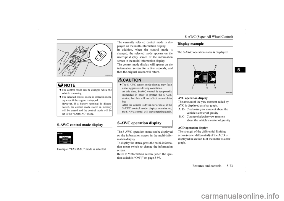
The S-AWC operation status is displayed.
NOTE
The control mode can be changed while the vehicle is moving. The selected control mode is stored in mem- ory even if the engine is stopped. However, if a battery terminal is discon-nected, the control mode stored in memory will be erased and the control mode will be set to the “TARMAC” mode.
S-AWC control mode display Example: “TARMAC” mode is selected.�ç
CAUTION The S-AWC control mode display may flash under aggressive driving conditions. At this time, S-AWC control is temporarily suspended in order to protect the S-AWCdevice, but this will not affect normal driv- ing. After the vehicle is driven for a while, if theS-AWC control mode display remains on, the S-AWC control will start operating again.
S-AWC operation display
Display example AYC operation display The amount of the yaw moment added by AYC is displayed as a bar graph.A, D- Clockwise yaw moment about the
vehicle’s center of gravity
B, C- Counterclockwise yaw moment
about the vehicle’s center of gravity
ACD operation display The strength of the differential limiting action (center differential) of the ACD is displayed in section E of the meter as a bar graph.
BK0200800US.bo
ok 73 ページ 2013年2月14日 木曜日 午後2時28分
Page 150 of 338
Instrument cluster
Features and controls 5-89
5
N00533001259
Your tire pressure monitoring system oper- ates on a radio frequency subject to Federal Communications Commission (FCC) Rules(For vehicles sold in U.S.A.) and Industry Canada Rules (For vehicles sold in Canada). This device complies
with Part 15 of FCC
Rules and Industry Canada licence-exempt RSS standard(s). Operation is subject to the following two con-ditions. This device may not cause harmful inter- ference. This device must accept any interference received, including interference that may cause undesired operation.
N00519000317 N00519100220
The speedometer shows the vehicle speed in miles per hour (mph) or kilometers per hour (km/h).
N00519200205
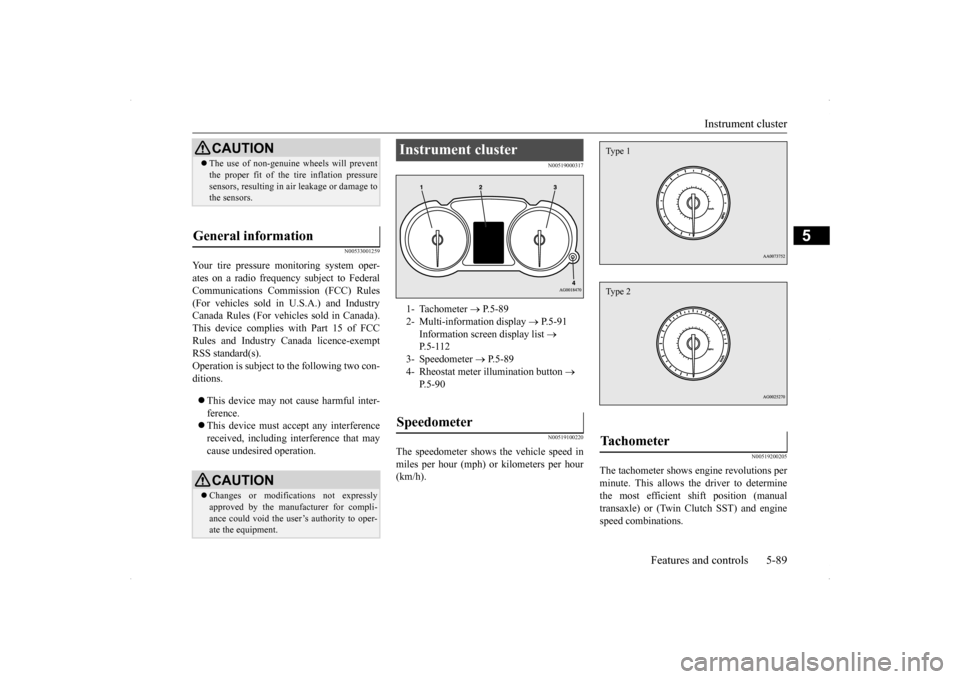
The tachometer shows engine revolutions perminute. This allows the driver to determinethe most efficient shift position (manual transaxle) or (Twin Clutch SST) and engine speed combinations.
CAUTION The use of non-genuine wheels will prevent the proper fit of the tire inflation pressure sensors, resulting in air leakage or damage to the sensors.
General information
CAUTION Changes or modifications not expressly approved by the manufacturer for compli- ance could void the user’s authority to oper- ate the equipment.
Instrument cluster 1- Tachometer
P.5-89
2- Multi-information display
P.5-91
Information screen display list
P.5-112
3- Speedometer
P.5-89
4- Rheostat meter illumination button
P.5-90
Speedometer
Tachometer Type 1Type 2
BK0200800US.bo
ok 89 ページ 2013年2月14日 木曜日 午後2時28分
Page 152 of 338
Multi-information display
Features and controls 5-91
5
N00555000207
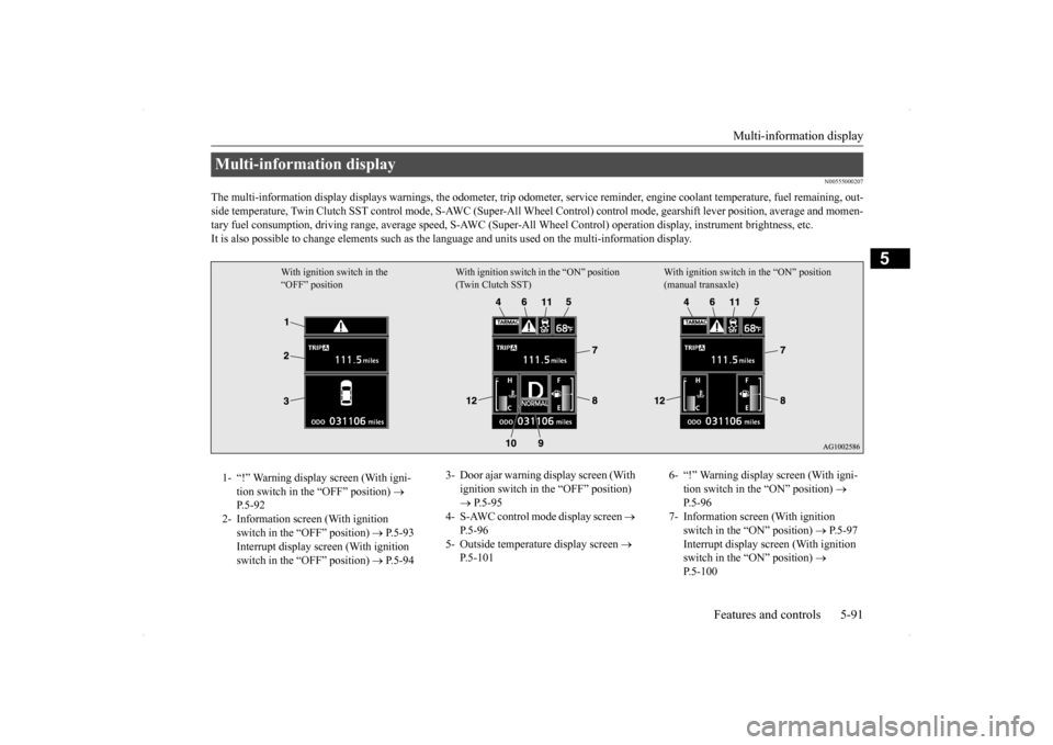
The multi-information display displays warnings, the odometer, tr
ip odometer, service reminder, engine coolant temperature, fue
l remaining, out-
side temperature, Twin Clutch SST contro
l mode, S-AWC (Super-All Wheel Control) co
ntrol mode, gearshift lever position, average
and momen-
tary fuel consumption, driving range, average speed, S-AWC (Super-
All Wheel Control) operation display, instrument brightness,
etc.
It is also possible to change elements such as the
language and units used on the multi-information display.
Multi-information display
With ignition switch in the “OFF” position
With ignition switch in the “ON” position (Twin Clutch SST)
With ignition switch in the “ON” position (manual transaxle)
1- “!” Warning display screen (With igni-
tion switch in the “OFF” position)
P.5-92
2- Information screen (With ignition
switch in the “OFF” position)
P.5-93
Interrupt display screen (With ignition switch in the “OFF” position)
P.5-94
3- Door ajar warning display screen (With
ignition switch in the “OFF” position) P.5-95
4- S-AWC control mode display screen
P.5-96
5- Outside temperature display screen
P.5-101
6- “!” Warning display screen (With igni-
tion switch in the “ON” position)
P.5-96
7- Information screen (With ignition
switch in the “ON” position)
P.5-97
Interrupt display screen (With ignition switch in the “ON” position)
P.5-100
BK0200800US.bo
ok 91 ページ 2013年2月14日 木曜日 午後2時28分
Page 192 of 338
Turn signal lever
Features and controls 5-131
5
N00522601558
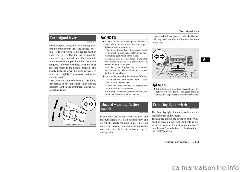
When changing lanes, or to making a gradual turn, hold the lever in
the “lane change” posi-
tion (1). It will return to the neutral position when you let go. Use the full position (2) when making a normal turn. The lever willreturn to the neutral position when the turn is complete. There may be times when the lever does not return to the neutral position. Thisusually happens when the steering wheel isturned only slightly. You can easily return the lever by hand. Also, when you move the lever to (1) slightlythen release it, the turn signal lights and the indicator light in the instrument cluster will flash three times.
N00522700288
If you press the flasher switch, the front andrear turn signals will flash intermittently, and so will the hazard warning lights. This is an emergency warning system and should not beused when the vehicle is in motion, except for emergencies.
If you need to leave your vehicle, the flashers will keep working after the ignition switch is turned off.
N00522800351
The front fog lights illuminate only when the headlights are on low beam. Turning the knob in the direction of the “ON” position turns on the front fog lights as wellas the indicator in the instrument cluster. To turn them off, turn the knob in the direction of the “OFF” position.
Turn signal lever
NOTE
A light in the instrument panel flashes to show when the front and rear turn signal lights are working properly. If this light flashes faster than usual, check for a burned out turn signal light bulb or mal-functioning connection in the signal. If the panel light does not come on when the lever is moved, check for a blown fuse or aburned out bulb in the panel. Have the system inspected by your autho- rized Mitsubishi Motors dealer or a repairfacility of your choice. It is possible to modify functions as follows: • Deactivate the turn signal light 3-flash function for lane changes. • Adjust the time required to operate the lever for the 3-flash function. For further information, please contact your authorized Mitsubishi Motors dealer.
Hazard warning flasher switch
NOTE
If the flashers are used for several hours, the battery will run down. This could make it difficult or impossible to restart your vehicle.
Front fog light switch
BK0200800US.book
131 ページ 2013年2月14日 木曜日 午後2時28分
Page 212 of 338

Bluetooth® 2.0 interface
Features and controls 5-151
5
“
N00565800019
If an incoming phone call is received whilethe ignition switch is in the “ACC” or “ON”position, the audio system will be automati- cally turned on and switched to the incoming call, even when the audio system was origi-nally off. The voice guide announcement for the incoming call will be output from the frontpassenger’s seat speaker. If the CD player or radio was playing when the incoming call was received, the audio sys-tem will mute the sound from the CD player or radio and output only the incoming call. To receive the call, press the PICK-UP buttonon the steering wheel control switch. When the call is over,
the audio system will
return to its previous state.
N00565900010
At any time during a call, you can mute thevehicle microphone. Pressing the SPEECH button and then saying “Mute” during a call will turn ON the mute function and mute the microphone.Saying “Mute off” in the same way will turn off the mute function and cancel the mute on the microphone.
N00566600014
The Bluetooth
® 2.0 interface can switch
between hands-free mode (hands-free calls) and private mode (calls using cellular phone). If you press the SPEECH button and say“Transfer call” during a hands-free call, you can stop the hands-free mode and talk in pri- vate mode. To return to hands-free mode, press the SPEECH button again and say “Transfer call.”
N00566000018
The Bluetooth
® 2.0 interface has 2 types of
unique phonebooks that are different from thephonebook stored in the cellular phone. They
are the vehicle phonebook and the mobile phonebook. These phonebooks are used to register tele- phone numbers and make calls to desirednumbers via voice recognition function.
N00566101117
This phonebook is us
ed when making calls
with the voice recognition function. Up to 32 names can be registered in the vehi- cle phonebook per language.Also, each entry has 4 locations associated with: home, work, mobile and other. You can register one telephone number for each loca-tion. You can register a desired name as a name for any phonebook entry registered in the vehicle phonebook.Names and telephone numbers can be changed later on. The vehicle phonebook can be used with all paired cellular phones.
Receiving calls
Mute function Switching between hands-free mode and private mode Phonebook function
NOTE
Disconnecting the battery cable will not delete information registered in the phone- book.
Vehicle phonebook
BK0200800US.book
151 ページ 2013年2月14日 木曜日 午後2時28分