clock MITSUBISHI LANCER EVOLUTION 2014 10.G Owners Manual
[x] Cancel search | Manufacturer: MITSUBISHI, Model Year: 2014, Model line: LANCER EVOLUTION, Model: MITSUBISHI LANCER EVOLUTION 2014 10.GPages: 338, PDF Size: 40.99 MB
Page 21 of 338
Filling the fuel tank 3-4 General information
3
N00301100753
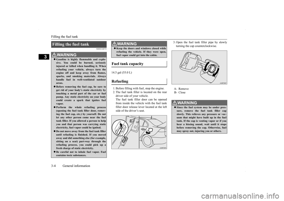
14.5 gal (55.0 L) 1. Before filling with fuel, stop the engine. 2. The fuel tank filler is located on the reardriver side of your vehicle. The fuel tank filler door can be opened from inside the vehicle with the fuel tankfiller door release lever located at the left side of the driver’s seat.
3. Open the fuel tank filler pipe by slowly turning the cap counterclockwise.
Filling the fuel tank
WA R N I N G Gasoline is highly flammable and explo- sive. You could be burned, seriously injured or killed when handling it. When refueling your vehicle, always turn theengine off and keep away from flames, sparks, and smoking materials. Always handle fuel in well-ventilated outdoorareas. Before removing the fuel cap, be sure to get rid of your body’s static electricity by touching a metal part of the car or fuel pump. Any static electricity on your bodycould create a spark that ignites fuel vapor. Perform the whole refueling process (opening the fuel tank filler door, remov- ing the fuel cap, etc.) by yourself. Do notlet any other person come near the fuel tank filler. If you allowed a person to help you and that person was carrying staticelectricity, fuel vapor could be ignited. Do not move away from the fuel tank filler until refueling is finished. If you moved away and did something else (for example, sitting on a seat) part-way through the refueling process, you could pick up a fresh charge of static electricity. Be careful not to inhale fuel vapor. Fuel contains toxic substances.
Keep the doors and windows closed while refueling the vehicle. If they were open, fuel vapor could get into the cabin.
Fuel tank capacity Refueling
WA R N I N G
�ç
A- Remove B- Close WA R N I N G Since the fuel system may be under pres- sure, remove the fuel tank filler capslowly. This relieves any pressure or vac- uum that might have built up in the fuel tank. If the cap is venting vapor or if youhear a hissing sound, wait until it stops before removing the cap. Otherwise, fuel may spray out, injuring you or others.
�ç
BK0200800US.bo
ok 4 ページ 2013年2月14日 木曜日 午後2時28分
Page 22 of 338
Modifications to and racing of your vehicle
General information 3-5
3
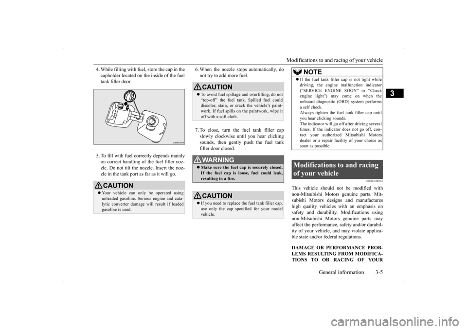
4. While filling with fuel, store the cap in the capholder located on the inside of the fuel tank filler door. 5. To fill with fuel correctly depends mainly on correct handling of the fuel filler noz- zle. Do not tilt the nozzle. Insert the noz-zle in the tank port as far as it will go.
6. When the nozzle stops automatically, do not try to add more fuel. 7. To close, turn the fuel tank filler cap slowly clockwise until you hear clickingsounds, then gently push the fuel tank filler door closed.
N00301600165
This vehicle should not be modified withnon-Mitsubishi Motors genuine parts. Mit- subishi Motors designs and manufactureshigh quality vehicles
with an emphasis on
safety and durability. Modifications using non-Mitsubishi Motors genuine parts mayaffect the performance, safety and/or durabil- ity of your vehicle, and may violate applica- ble state and/or federal regulations. DAMAGE OR PERFORMANCE PROB- LEMS RESULTING FROM MODIFICA- TIONS TO OR RACING OF YOUR
CAUTION Your vehicle can only be operated using unleaded gasoline. Serious engine and cata-lytic converter damage will result if leaded gasoline is used.
�ç
CAUTION To avoid fuel spillage and overfilling, do not “top-off” the fuel tank. Spilled fuel coulddiscolor, stain, or crack the vehicle’s paint- work. If fuel spills on the paintwork, wipe it off with a soft cloth.WA R N I N G Make sure the fuel cap is securely closed. If the fuel cap is loose, fuel could leak, resulting in a fire.CAUTION If you need to replace the fuel tank filler cap, use only the cap specified for your model vehicle.
NOTE
If the fuel tank filler
cap is not tight while
driving, the engine malfunction indicator (“SERVICE ENGINE SOON” or “Check engine light”) may come on when the onboard diagnostic (OBD) system performsa self check. Always tighten the fuel tank filler cap until you hear clicking sounds.The indicator will go off after driving several times. If the indicator does not go off, con- tact your authorized Mitsubishi Motorsdealer or a repair facility of your choice as soon as possible.
Modifications to and racing of your vehicle
BK0200800US.bo
ok 5 ページ 2013年2月14日 木曜日 午後2時28分
Page 134 of 338
S-AWC (Super-All Wheel Control)
Features and controls 5-73
5
The currently selected control mode is dis- played on the multi-information display. In addition, when the control mode is changed, the selected mode appears on theinterrupt display screen of the information screen in the multi-information display. The control mode display will appear on theinformation screen for a few seconds, and then the original screen will return.
N00542500048
The S-AWC operation status can be displayedon the information screen in the multi-infor- mation display.To display the status, press the multi-informa- tion meter switch to change the information screen.Refer to “Information screen (when the igni- tion switch is “ON”)” on page 5-97.
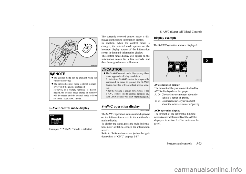
The S-AWC operation status is displayed.
NOTE
The control mode can be changed while the vehicle is moving. The selected control mode is stored in mem- ory even if the engine is stopped. However, if a battery terminal is discon-nected, the control mode stored in memory will be erased and the control mode will be set to the “TARMAC” mode.
S-AWC control mode display Example: “TARMAC” mode is selected.�ç
CAUTION The S-AWC control mode display may flash under aggressive driving conditions. At this time, S-AWC control is temporarily suspended in order to protect the S-AWCdevice, but this will not affect normal driv- ing. After the vehicle is driven for a while, if theS-AWC control mode display remains on, the S-AWC control will start operating again.
S-AWC operation display
Display example AYC operation display The amount of the yaw moment added by AYC is displayed as a bar graph.A, D- Clockwise yaw moment about the
vehicle’s center of gravity
B, C- Counterclockwise yaw moment
about the vehicle’s center of gravity
ACD operation display The strength of the differential limiting action (center differential) of the ACD is displayed in section E of the meter as a bar graph.
BK0200800US.bo
ok 73 ページ 2013年2月14日 木曜日 午後2時28分
Page 183 of 338
Warning lights 5-122 Features and controls
5
N00520300147 N00520400483
This light comes on when the ignition switch is turned to the “ON” position (engine off).When the engine is started, the light should go off a few seconds later. A warning is also displayed in the multi-information display.The warning light also illuminates after start-ing the engine under the following condi- tions. When the parking brake is still applied. When the brake fluid level is low. When the brake system circuit is not working properly.
Before driving, be sure that the parking brake is fully released and brake warning light isoff.
N00520500787
This indicator is a part of the onboard diag- nostic (OBD) system which monitors the emissions, engine control system or TwinClutch SST control sy
stem. If a problem is
detected in one of these systems, this indica- tor illuminates or flashes. When the ignitionswitch is turned to the “ON” position, thisindicator normally comes on and goes off after the engine has started. This indicator will come on if the fuel tank filler cap is not properly tightened. If thisindicator comes on and stays on after refuel- ing, stop the engine and check that the cap is properly tightened. (Turn the cap clockwiseuntil you hear clicking sounds.) If this indicator does not go off after several seconds or lights up while driving, have thesystem checked as soon as possible at an authorized Mitsubishi Motors dealer or a repair facility of your choice.
Warning lights Brake warning light
NOTE
Under conditions such as sporty driving, the brake fluid in the tank may move and the warning light may come on temporarily.If the warning light goes out after a while, there is not a problem with the brake system and the vehicle can be driven normally.
CAUTION If the brake warning light and the Anti-lock braking system warning light are illuminated at the same time, the braking force distribu- tion function will not operate, so the vehicle may be destabilized during sudden brakingunder the following conditions.• When the brake warning light does not goout even when the parking brake is released.• When the brake warning light stays onwhile driving.• If the above occurs, avoid sudden brakingand high-speed driving. Park the vehicle in a safe place, and contact an authorized Mit-subishi Motors dealer or a repair facility of your choice as soon as possible.
The vehicle should be brought to a halt in the following manner when brake performance is deteriorated.• Confirm that the vehicle slows down whenyou press down on the brake pedal harderthan usual. In some cases, the brake pedal may go all the way to the floor.• Should the brakes fail, use engine brakingto reduce your speed and slowly apply the parking brake.Depress the brake pedal to illuminate the stop lights to alert the vehicles behind you.
Engine malfunction indicator (“SERVICE ENGINE SOON” or “Check engine light”)
BK0200800US.book
122 ページ 2013年2月14日 木曜日 午後2時28分
Page 243 of 338
Automatic air conditioning with
Fahrenheit scale (if so equipped)
7-4 Comfort controls
7
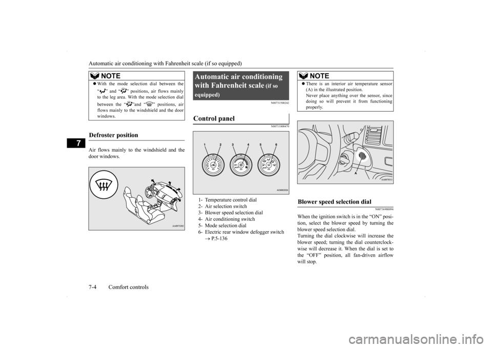
Air flows mainly to the windshield and the door windows.
N00731500242 N00711800470
N00736900094
When the ignition switch is in the “ON” posi- tion, select the blower speed by turning the blower speed selection dial.Turning the dial clockwise will increase the blower speed; turning the dial counterclock- wise will decrease it. When the dial is set tothe “OFF” position, all fan-driven airflow will stop.
NOTE
With the mode selection dial between the “ ” and “ ” positions, air flows mainly to the leg area. With the mode selection dial between the “ ”and “ ” positions, air flows mainly to the windshield and the doorwindows.
Defroster position
Automatic air conditioning with Fahrenheit scale
(if so
equipped)Control panel
1- Temperature control dial 2- Air selection switch 3- Blower speed selection dial4- Air conditioning switch 5- Mode selection dial 6- Electric rear window defogger switch
P.5-136
NOTE
There is an interior air temperature sensor (A) in the illustrated position. Never place anything over the sensor, since doing so will prevent it from functioning properly.
Blower speed selection dial
BK0200800US.bo
ok 4 ページ 2013年2月14日 木曜日 午後2時28分
Page 244 of 338
Automatic air conditioning with
Fahrenheit scale (if so equipped)
Comfort controls 7-5
7
N00737000223
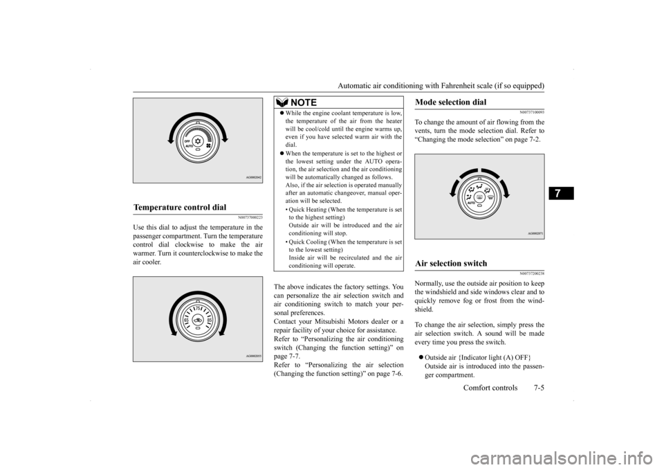
Use this dial to adjust the temperature in the passenger compartment. Turn the temperaturecontrol dial clockwise to make the air warmer. Turn it counterclockwise to make the air cooler.
The above indicates the factory settings. You can personalize the air selection switch and air conditioning switch to match your per-sonal preferences. Contact your Mitsubishi Motors dealer or a repair facility of your choice for assistance.Refer to “Personalizing the air conditioning switch (Changing the function setting)” on page 7-7.Refer to “Personalizing the air selection (Changing the function setting)” on page 7-6.
N00737100093
To change the amount of air flowing from the vents, turn the mode selection dial. Refer to“Changing the mode selection” on page 7-2.
N00737200238
Normally, use the outside air position to keepthe windshield and side windows clear and toquickly remove fog or frost from the wind- shield. To change the air selection, simply press the air selection switch. A sound will be madeevery time you press the switch. Outside air {Indicator light (A) OFF} Outside air is introduced into the passen- ger compartment.
Temperature control dial
NOTE
While the engine coolant temperature is low, the temperature of the air from the heater will be cool/cold until the engine warms up, even if you have selected warm air with the dial. When the temperature is set to the highest or the lowest setting under the AUTO opera-tion, the air selection and the air conditioning will be automatically changed as follows. Also, if the air selection is operated manuallyafter an automatic changeover, manual oper- ation will be selected. • Quick Heating (When the temperature is set to the highest setting) Outside air will be introduced and the airconditioning will stop. • Quick Cooling (When the temperature is set to the lowest setting) Inside air will be recirculated and the air conditioning will operate.
Mode selection dial
Air selection switch
BK0200800US.bo
ok 5 ページ 2013年2月14日 木曜日 午後2時28分
Page 248 of 338
Automatic air conditioning with
Celsius scale (if so equipped)
Comfort controls 7-9
7
For quick defrosting 1. Set the mode selection dial to the “ ” position. 2. Set your blower to the maximum speed. 3. Set the temperature to the highest posi-tion.
N00731500255 N00711800483
N00736900111
When the ignition switch is in the “ON” posi- tion, select the blower speed by turning the blower speed selection dial.Turning the dial clockwise will increase the blower speed; turning the dial counterclock- wise will decrease it. When the dial is set to
NOTE
While the mode selection dial is set between “ ” and “ ” position, the air condition- ing compressor will run automatically. The outside air position will also be selectedautomatically. If the mode selection dial is set between “ ” and “ ” you cannot turn the air con- ditioning off or select the recirculation posi- tion. This prevents the windows from fogging up. To defog quickly, direct
the air flow from the
side vents toward the door windows.
When defrosting, do not set the temperature control dial to the maximum cool position. This will blow cool air on the window glass and fog it up.
Automatic air conditioning with Celsius scale
(if so
equipped)Control panel
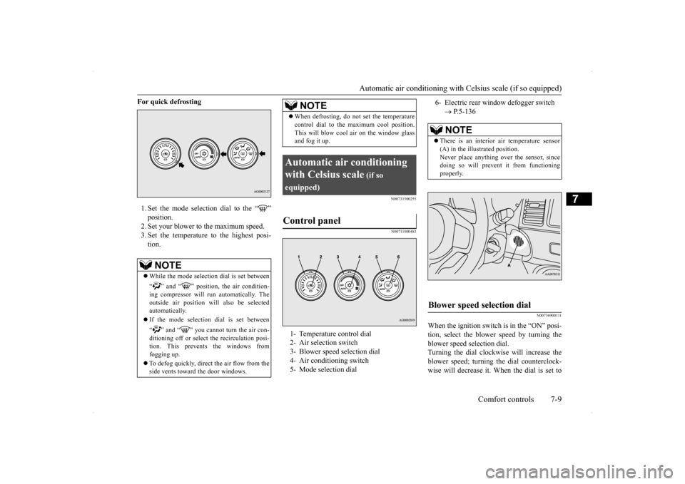
1- Temperature control dial 2- Air selection switch 3- Blower speed selection dial 4- Air conditioning switch5- Mode selection dial
NOTE
6- Electric rear window defogger switch
P.5-136NOTE
There is an interior air temperature sensor (A) in the illustrated position.Never place anything over the sensor, since doing so will prevent it from functioning properly.
Blower speed selection dial
BK0200800US.bo
ok 9 ページ 2013年2月14日 木曜日 午後2時28分
Page 249 of 338
Automatic air conditioning with
Celsius scale (if so equipped)
7-10 Comfort controls
7
the “OFF” position, all fan-driven airflow will stop.
N00737000236
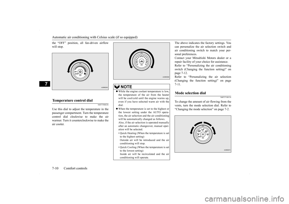
Use this dial to adjust the temperature in thepassenger compartment. Turn the temperaturecontrol dial clockwise to make the air warmer. Turn it counterclockwise to make the air cooler.
The above indicates the factory settings. You can personalize the air selection switch and air conditioning switch to match your per- sonal preferences.Contact your Mitsubishi Motors dealer or a repair facility of your choice for assistance. Refer to “Personalizing the air conditioningswitch (Changing the function setting)” on page 7-12. Refer to “Personalizing the air selection(Changing the function setting)” on page7-11.
N00737100136
To change the amount of air flowing from thevents, turn the mode selection dial. Refer to “Changing the mode selection” on page 7-2.
Temperature control dial
NOTE
While the engine coolant temperature is low, the temperature of the air from the heater will be cool/cold until the engine warms up,even if you have selected warm air with the dial. When the temperature is set to the highest or the lowest setting under the AUTO opera- tion, the air selection and the air conditioningwill be automatically changed as follows. Also, if the air selection is operated manually after an automatic changeover, manual oper-ation will be selected. • Quick Heating (When the temperature is set to the highest setting) Outside air will be introduced and the air conditioning will stop. • Quick Cooling (When the temperature is set to the lowest setting)Inside air will be recirculated and the air conditioning will operate.
Mode selection dial
BK0200800US.bo
ok 10 ページ 2013年2月14日 木曜日 午後2時28分
Page 254 of 338
Air purifier
Comfort controls 7-15
7
The air conditioning should be operated for at least five minutes each week, even in coldweather. This includes the quick defrosting mode. Operating the air condition system weekly maintains lubrication of the compres-sor internal parts to keep the air conditioning in the best operating condition.
N00733800151
The air conditioning system is equipped with an air filter to remove pollen and dust. The air filter’s ability to collect pollen and dirt is reduced as it becomes dirty, so replaceit periodically. For the maintenance interval, refer to the “WARRANTY AND MAINTE- NANCE MANUAL”.
N00734200455
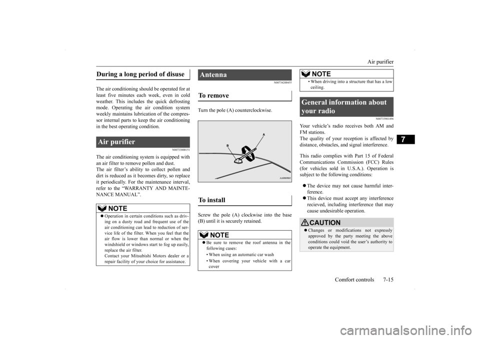
Turn the pole (A) counterclockwise. Screw the pole (A) clockwise into the base (B) until it is securely retained.
N00733901494
Your vehicle’s radio receives both AM and FM stations.The quality of your reception is affected by distance, obstacles, and signal interference. This radio complies with Part 15 of Federal Communications Commission (FCC) Rules(for vehicles sold in U.S.A.). Operation is subject to the following conditions: The device may not cause harmful inter- ference. This device must accept any interference recieved, including interference that may cause undesirable operation.
During a long period of disuse Air purifier
NOTE
Operation in certain conditions such as driv- ing on a dusty road and frequent use of the air conditioning can lead to reduction of ser- vice life of the filter.
When you feel that the
air flow is lower than
normal or when the
windshield or windows start to fog up easily, replace the air filter. Contact your Mitsubishi Motors dealer or arepair facility of your choice for assistance.
Antenna To remove To install
NOTE
Be sure to remove the roof antenna in the following cases: • When using an automatic car wash • When covering your vehicle with a car cover
• When driving into a structure that has a lowceiling.
General information about your radio
CAUTION Changes or modifications not expressly approved by the party meeting the above conditions could void the user’s authority to operate the equipment.NOTE
BK0200800US.bo
ok 15 ページ 2013年2月14日 木曜日 午後2時28分
Page 262 of 338
Tools and jack
For emergencies 8-5
8
8. If the reserve tank needs coolant, you will probably also need to add coolant to the radiator. Do not loosen or remove the radiator cap until the engine has cooleddown. 9. Start the engine, and slowly add coolant, up to the bottom of the filler neck. Useplain water if you have to (and replace it with the right coolant as soon as possible).
10. Replace the radiator cap and tighten it
fully. Check the engine coolant tempera- ture display on the multi-information dis- play. You can start driving again when thebar graph for the engine coolant tempera- ture display returns to the normal zone.
11. Have your vehicle checked by your autho-
rized Mitsubishi Motors dealer or a repair facility of your choice.
N00836600311
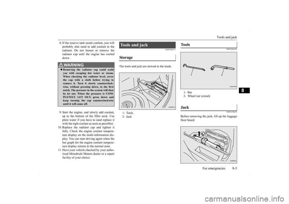
The tools and jack are stowed in the trunk.
N00832600140 N00832700239
Before removing the jack, lift up the luggage floor board.
WA R N I N G Removing the radiator cap could scald you with escaping hot water or steam.When checking the radiator level, cover the cap with a cloth before trying to remove it. Turn it slowly counterclock-wise, without pressing down, to the first notch. The pressure in the system will then be let out. When the pressure is COM-PLETELY LET OUT, press down and keep turning the cap counterclockwise until it will come off.
Tools and jack Storage 1- Tools 2- Jack
Tools 1- Bar 2- Wheel nut wrenchJack
BK0200800US.bo
ok 5 ページ 2013年2月14日 木曜日 午後2時28分