fuel cap MITSUBISHI LANCER EVOLUTION 2014 10.G Owners Manual
[x] Cancel search | Manufacturer: MITSUBISHI, Model Year: 2014, Model line: LANCER EVOLUTION, Model: MITSUBISHI LANCER EVOLUTION 2014 10.GPages: 338, PDF Size: 40.99 MB
Page 21 of 338
Filling the fuel tank 3-4 General information
3
N00301100753
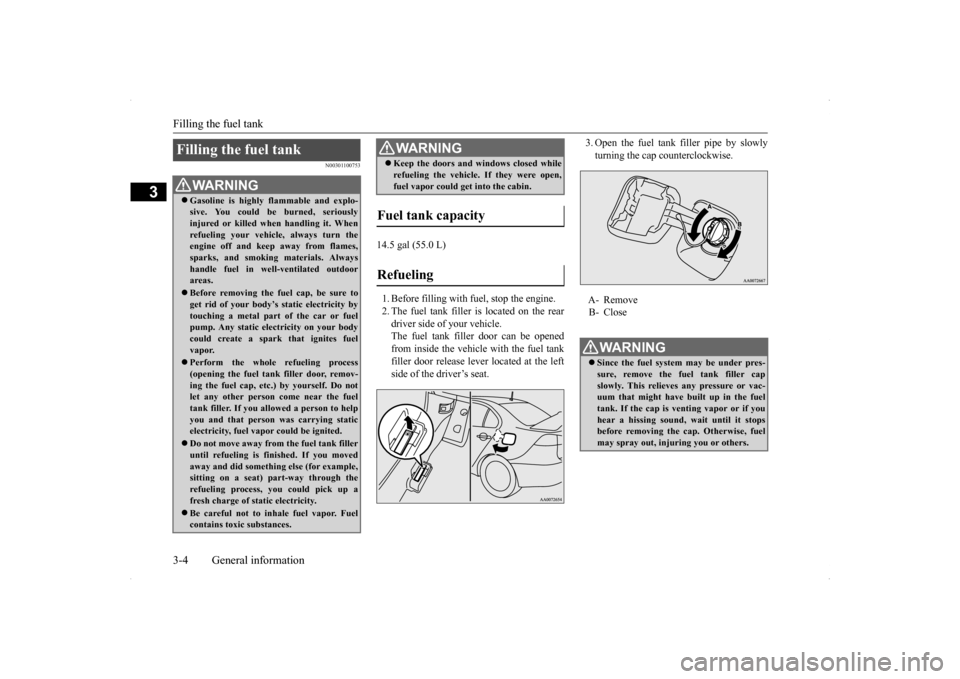
14.5 gal (55.0 L) 1. Before filling with fuel, stop the engine. 2. The fuel tank filler is located on the reardriver side of your vehicle. The fuel tank filler door can be opened from inside the vehicle with the fuel tankfiller door release lever located at the left side of the driver’s seat.
3. Open the fuel tank filler pipe by slowly turning the cap counterclockwise.
Filling the fuel tank
WA R N I N G Gasoline is highly flammable and explo- sive. You could be burned, seriously injured or killed when handling it. When refueling your vehicle, always turn theengine off and keep away from flames, sparks, and smoking materials. Always handle fuel in well-ventilated outdoorareas. Before removing the fuel cap, be sure to get rid of your body’s static electricity by touching a metal part of the car or fuel pump. Any static electricity on your bodycould create a spark that ignites fuel vapor. Perform the whole refueling process (opening the fuel tank filler door, remov- ing the fuel cap, etc.) by yourself. Do notlet any other person come near the fuel tank filler. If you allowed a person to help you and that person was carrying staticelectricity, fuel vapor could be ignited. Do not move away from the fuel tank filler until refueling is finished. If you moved away and did something else (for example, sitting on a seat) part-way through the refueling process, you could pick up a fresh charge of static electricity. Be careful not to inhale fuel vapor. Fuel contains toxic substances.
Keep the doors and windows closed while refueling the vehicle. If they were open, fuel vapor could get into the cabin.
Fuel tank capacity Refueling
WA R N I N G
�ç
A- Remove B- Close WA R N I N G Since the fuel system may be under pres- sure, remove the fuel tank filler capslowly. This relieves any pressure or vac- uum that might have built up in the fuel tank. If the cap is venting vapor or if youhear a hissing sound, wait until it stops before removing the cap. Otherwise, fuel may spray out, injuring you or others.
�ç
BK0200800US.bo
ok 4 ページ 2013年2月14日 木曜日 午後2時28分
Page 22 of 338
Modifications to and racing of your vehicle
General information 3-5
3
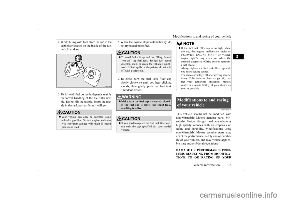
4. While filling with fuel, store the cap in the capholder located on the inside of the fuel tank filler door. 5. To fill with fuel correctly depends mainly on correct handling of the fuel filler noz- zle. Do not tilt the nozzle. Insert the noz-zle in the tank port as far as it will go.
6. When the nozzle stops automatically, do not try to add more fuel. 7. To close, turn the fuel tank filler cap slowly clockwise until you hear clickingsounds, then gently push the fuel tank filler door closed.
N00301600165
This vehicle should not be modified withnon-Mitsubishi Motors genuine parts. Mit- subishi Motors designs and manufactureshigh quality vehicles
with an emphasis on
safety and durability. Modifications using non-Mitsubishi Motors genuine parts mayaffect the performance, safety and/or durabil- ity of your vehicle, and may violate applica- ble state and/or federal regulations. DAMAGE OR PERFORMANCE PROB- LEMS RESULTING FROM MODIFICA- TIONS TO OR RACING OF YOUR
CAUTION Your vehicle can only be operated using unleaded gasoline. Serious engine and cata-lytic converter damage will result if leaded gasoline is used.
�ç
CAUTION To avoid fuel spillage and overfilling, do not “top-off” the fuel tank. Spilled fuel coulddiscolor, stain, or crack the vehicle’s paint- work. If fuel spills on the paintwork, wipe it off with a soft cloth.WA R N I N G Make sure the fuel cap is securely closed. If the fuel cap is loose, fuel could leak, resulting in a fire.CAUTION If you need to replace the fuel tank filler cap, use only the cap specified for your model vehicle.
NOTE
If the fuel tank filler
cap is not tight while
driving, the engine malfunction indicator (“SERVICE ENGINE SOON” or “Check engine light”) may come on when the onboard diagnostic (OBD) system performsa self check. Always tighten the fuel tank filler cap until you hear clicking sounds.The indicator will go off after driving several times. If the indicator does not go off, con- tact your authorized Mitsubishi Motorsdealer or a repair facility of your choice as soon as possible.
Modifications to and racing of your vehicle
BK0200800US.bo
ok 5 ページ 2013年2月14日 木曜日 午後2時28分
Page 119 of 338
Twin Clutch SST (Sportronic Shif
t Transmission) (if so equipped)
5-58 Features and controls
5
N00513100156
The table below shows the maximum rec- ommended driving speed for in each gear.Do not drive near or at these speeds forprolonged periods of time. Do not use the gearshift lever as a han- drest. This can result in premature wear of the transaxle shift forks.
N00539700017
The Twin Clutch SST is a transmission that, through integrated control of the engine and transmission, is able to achieve both the smooth shifting of an automatic transaxle andthe acceleration and fuel economy close to amanual transaxle. In addition, the control mode can be selected from three types to suit the driving conditions.Together with manual shifting, the transmis- sion is capable of responding to a variety of driving circumstances. Twin Clutch SST control mode
P.5-62
Manual shift
P.5-64
N00539800063
As an additional safety precaution, models equipped with a Twin Clutch SST have a shift-lock device that holds the gearshift lever in the “P” (PARK) position. To move thegearshift lever from the “P” (PARK) position to another position, follow the steps below. 1. Press and hold the brake pedal down.
2. Move the gearshift lever to the desired position.
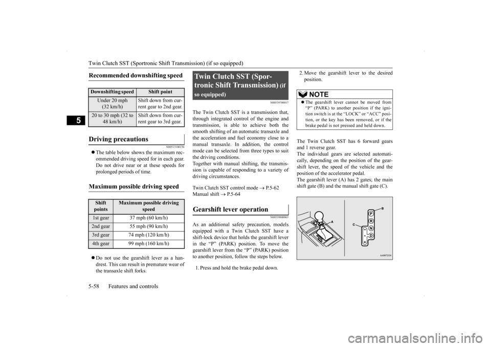
The Twin Clutch SST has 6 forward gears and 1 reverse gear.The individual gears are selected automati- cally, depending on the position of the gear- shift lever, the speed of the vehicle and theposition of the accelerator pedal. The gearshift lever (A) has 2 gates; the main shift gate (B) and the manual shift gate (C).
Recommended downshifting speed
Downshifting speed
Shift point
Under 20 mph (32 km/h)
Shift down from cur- rent gear to 2nd gear.
20 to 30 mph (32 to
48 km/h)
Shift down from cur- rent gear to 3rd gear.
Driving precautions
Maximum possible driving speed
Shift points
Maximum possible driving
speed
1st gear 37 mph (60 km/h)2nd gear 55 mph (90 km/h)3rd gear 74 mph (120 km/h)4th gear 99 mph (160 km/h)
Twin Clutch SST (Spor- tronic Shift Transmission)
(if
so equipped)Gearshift lever operation
NOTE
The gearshift lever cannot be moved from “P” (PARK) to another position if the igni- tion switch is at the “LOCK” or “ACC” posi-tion, or the key has been removed, or if the brake pedal is not pressed and held down.
BK0200800US.bo
ok 58 ページ 2013年2月14日 木曜日 午後2時28分
Page 148 of 338
Tire pressure monitoring system
Features and controls 5-87
5
Each tire, including the spare (if provided), should be checked monthly when cold and inflated to the inflation pressure recom-mended by the vehicle manufacturer on the vehicle placard or tire inflation pressure label. (If your vehicle has tires of a different sizethan the size indicated on the vehicle placard or tire inflation pressure label, you should determine the proper tire inflation pressurefor those tires.) As an added safety feature, your vehicle has been equipped with a tire pressure monitoringsystem (TPMS) that illuminates a low tire pressure telltale when one or more of your tires is significantly under-inflated.Accordingly, when the low tire pressure tell-tale illuminates, you should stop and check your tires as soon as possible, and inflate them to the proper pres
sure. Driving on a sig-
nificantly under-inflated tire causes the tire to overheat and can lead to tire failure.
Under-inflation also reduces fuel efficiency and tire tread life, and may affect the vehi- cle’s handling and stopping ability. Please note that the TPMS is not a substitute forproper tire maintenance, and it is the driver’s responsibility to maintain correct tire pres- sure, even if under-inflation has not reachedthe level to trigger illumination of the TPMS low tire pressure telltale. Your vehicle has also been equipped with aTPMS malfunction indicator to indicate whenthe system is not operating properly. The TPMS malfunction indicator is combined with the low tire pressure telltale.When the system detects a malfunction, the telltale will flash for approximately one min- ute and then remain continuously illuminated.This sequence will continue upon subsequent vehicle start-ups as long as the malfunction exists.When the malfunction indicator is illumi- nated, the system may not be able to detect or signal low tire pressure as intended.TPMS malfunctions may occur for a variety of reasons, including the installation of replacement or alternat
e tires or wheels on the
vehicle that prevent the TPMS from function- ing properly. Always check the TPMS mal- function telltale after replacing one or moretires or wheels on your vehicle to ensure that the replacement or alternate tires and wheels
allow the TPMS to continue to function prop- erly.
N00532800439
1. If the tire pressure monitoring system warning light illuminates, avoid hard braking, sharp steering maneuvers andhigh speeds. You should stop and adjustthe tires to the proper inflation pressure as soon as possible. Adjust the spare tire at the same time. Refer to “Tires” on page9-12.
NOTE
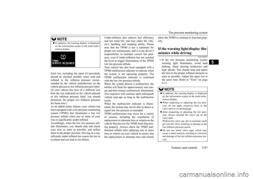
In addition, the warning display is displayed on the information screen in the multi-infor- mation display.
If the warning light/display illu- minates while driving
NOTE
In addition, the warning display is displayed on the information screen in the multi-infor- mation display. When inspecting or adjusting the tire pres- sure, do not apply excessive force to thevalve stem to avoid breakage. After inspecting or adjusting the tire pres- sure, always reinstall the valve cap on the valve stem. Without the valve cap, dirt or moisture could get into the valve, resulting in damage to the tire inflation pressure sensor. Do not use metal valve caps, which may cause a metal reaction, resulting in corrosionand damage of the tire inflation pressure sen- sors.
BK0200800US.bo
ok 87 ページ 2013年2月14日 木曜日 午後2時28分
Page 183 of 338
Warning lights 5-122 Features and controls
5
N00520300147 N00520400483
This light comes on when the ignition switch is turned to the “ON” position (engine off).When the engine is started, the light should go off a few seconds later. A warning is also displayed in the multi-information display.The warning light also illuminates after start-ing the engine under the following condi- tions. When the parking brake is still applied. When the brake fluid level is low. When the brake system circuit is not working properly.
Before driving, be sure that the parking brake is fully released and brake warning light isoff.
N00520500787
This indicator is a part of the onboard diag- nostic (OBD) system which monitors the emissions, engine control system or TwinClutch SST control sy
stem. If a problem is
detected in one of these systems, this indica- tor illuminates or flashes. When the ignitionswitch is turned to the “ON” position, thisindicator normally comes on and goes off after the engine has started. This indicator will come on if the fuel tank filler cap is not properly tightened. If thisindicator comes on and stays on after refuel- ing, stop the engine and check that the cap is properly tightened. (Turn the cap clockwiseuntil you hear clicking sounds.) If this indicator does not go off after several seconds or lights up while driving, have thesystem checked as soon as possible at an authorized Mitsubishi Motors dealer or a repair facility of your choice.
Warning lights Brake warning light
NOTE
Under conditions such as sporty driving, the brake fluid in the tank may move and the warning light may come on temporarily.If the warning light goes out after a while, there is not a problem with the brake system and the vehicle can be driven normally.
CAUTION If the brake warning light and the Anti-lock braking system warning light are illuminated at the same time, the braking force distribu- tion function will not operate, so the vehicle may be destabilized during sudden brakingunder the following conditions.• When the brake warning light does not goout even when the parking brake is released.• When the brake warning light stays onwhile driving.• If the above occurs, avoid sudden brakingand high-speed driving. Park the vehicle in a safe place, and contact an authorized Mit-subishi Motors dealer or a repair facility of your choice as soon as possible.
The vehicle should be brought to a halt in the following manner when brake performance is deteriorated.• Confirm that the vehicle slows down whenyou press down on the brake pedal harderthan usual. In some cases, the brake pedal may go all the way to the floor.• Should the brakes fail, use engine brakingto reduce your speed and slowly apply the parking brake.Depress the brake pedal to illuminate the stop lights to alert the vehicles behind you.
Engine malfunction indicator (“SERVICE ENGINE SOON” or “Check engine light”)
BK0200800US.book
122 ページ 2013年2月14日 木曜日 午後2時28分
Page 236 of 338
Loading information Driving safety 6-7
6
Vehicle maximum load on the tire: load on an individual tire that is determined by distributing to each axle its share of the maximum loaded vehicle weight anddividing by two. Vehicle normal load on the tire: load on an individual tire that is determined by dis-tributing to each axle its share of the curb weight, accessory weight, and normal occupant weight and dividing by two. Maximum loaded vehicle weight: the sum of - (a) Curb weight; (b) Accessory weight;(c) Vehicle capacity weight; and (d) Production options weight. Curb weight: the weight of a motor vehi- cle with standard equipment including the maximum capacity of fuel, oil, and cool- ant. Accessory weight: the combined weight (in excess of those standard items which may be replaced) of automatic transmis-sion, power steering, power brakes, power windows, power seats, radio, and heater, to the extent that these items are availableas factory- installed equipment (whether installed or not). Vehicle capacity weight: the rated cargo and luggage load plus 150 lbs (68 kg)
*
times the vehicle’s designated seating capacity.
Production options weight: the combined weight of those installed regular produc- tion options weighing over 5 lbs (2.3 kg) in excess of those standard items whichthey replace, not previously considered in curb weight or accessory weight, includ- ing heavy duty brakes, ride levelers, roofrack, heavy duty battery, and special trim. Normal occupant weight: 150 lbs (68 kg)
*
times the number of specified occupants.(In your vehicle the number is 3) Occupant distribution: distribution of occupants in a vehicle as specified. (In your vehicle the distribution is 2 in front,1 in second row seat)
N00630100338
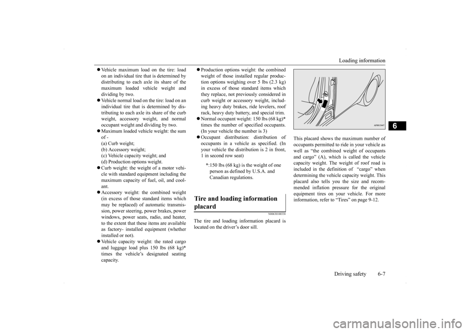
The tire and loading information placard is located on the driver’s door sill.
This placard shows the maximum number of occupants permitted to ride in your vehicle aswell as “the combined weight of occupants and cargo” (A), which is called the vehicle capacity weight. The weight of roof road isincluded in the definition of “cargo” when determining the vehicle capacity weight. This placard also tells you the size and recom-mended inflation pressure for the originalequipment tires on your vehicle. For more information, refer to “Tires” on page 9-12.
* :150 lbs (68 kg) is the weight of one person as defined by U.S.A. and Canadian regulations.
Tire and loading information placard
BK0200800US.bo
ok 7 ページ 2013年2月14日 木曜日 午後2時28分
Page 288 of 338
Tires
Vehicle care and maintenance 9-17
9
2 to 6 PSI from the cold inflation pressure. Do not let air out of the tires to get back to the specified cold pressure, or your tire pressure will be too low.Check your tires each time you refuel. If one tire looks lower than the others, check the pressure for all of them.You should also take the following safety pre- cautions: Keep your tires inflated to the recom- mended pressures. (See the tire and load-ing information placard attached to thedriver’s door sill.) Stay within the recommended load limits. Make sure that the weight of any load in your vehicle is evenly distributed. Drive at safe speeds. After filling your tires to the correct pres- sure, check them for damage and air leaks. Be sure to reinstall the caps on the valve stems.
N00939600397
N00939700037
The following maintenance steps are recom- mended: Check tire pressures regularly.
Have regular maintenance done on the wheel balance and front and rear suspen- sion alignment. Rotate your tires regularly as described in the “Tire rotation” section on page 9-18.
N00939800201
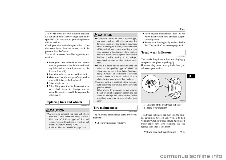
The standard-equipment tires use a high-gripcompound that gives superior grip.However, they wear more quickly than typi- cal passenger-car tires. Tread wear indicators are built into the origi- nal equipment tires on your vehicle to help you know when your tire
s should be replaced.
Many states have laws requiring that you replace your tires at this point.
Replacing tires and wheels
CAUTION Avoid using different size tires and wheels from the ones listed, and avoid the com- bined use of different types of tires and wheels. Using different size or type tires andwheels may affect driving safety. Refer to “Tires and wheels” on page 11-5.
Always use tires of the same size, same type, and same brand, and which have no wear dif- ferences. Using tires that differ in size, type, brand or the degree of wear, will increase the differential oil temperature, resulting in pos-sible damage to the driving system. Further, the drive train will be
subjected to excessive
loading, possibly leading to oil leakage,component seizure, or other serious prob- lems. Even if a wheel has the same rim size and offset as the specified type of wheel, its shape may prevent it from being fitted cor-rectly. Consult an authorized Mitsubishi Motors dealer or a repair facility of your choice before using wheels that you have. As your vehicle is equipped with a tire pres- sure monitoring system, use only Mitsubishigenuine wheels. Other wheels do not permit correct installa- tion of tire inflation pressure sensors and cancause air leakage and sensor failure, which would not be covered by your vehicle’s war- ranty.
Tire maintenance
CAUTION
Tread wear indicators 1- Location of the tread wear indicator 2- Tread wear indicator
BK0200800US.bo
ok 17 ページ 2013年2月14日 木曜日 午後2時28分
Page 292 of 338
General maintenance
Vehicle care and maintenance 9-21
9
N00940900244
Spark plugs must fire properly for good engine performance and emission-control.Do not reuse them by cleaning or regapping. Change them at the mileage listed in the “WARRANTY AND MAINTENANCEMANUAL”.
N00941000053
Check the hose surfaces for any heat andmechanical damage, hard and brittle rubber,cracking, tears, cuts and abrasions. Pay spe- cial attention to the hoses closest to high heat sources such as the exhaust manifold. Checkall the hose connections, such as clamps and couplings, to make sure
they are secure and
that there are no leaks. If you see any wear ordamage, replace the hoses immediately.
N00950100050
Have the valve clearance checked at anauthorized Mitsubishi Motors dealer at themileage specified in the “WARRANTY AND MAINTENANCE MANUAL”. If the engine sounds abnormally loud, haveadjustments made by an authorized Mitsubishi Motors dealer.
N00941300085
Check these regularly for damage or leaks in the fuel lines and connections. Check the fuel tank filler cap for damage or looseness. Pay special attention to the fuel lines closest to
high heat sources such as the exhaust mani- fold.
N00941400116
If the fuel-vapor vent line is clogged or dam- aged, the fuel-vapor mixture will escape, pol- luting the air.Have the system checked at an authorized Mitsubishi Motors dealer at the mileage spec- ified in the “WARRANTY AND MAINTE-NANCE MANUAL”.
N00941500159
The next pages list the maintenance servicerecommended by Mitsubishi Motors Corpo- ration. In addition to the general maintenance that needs to be performed at the times listed,
NOTE
To meet government regulations and pro- mote cleaner air, your vehicle is equipped with an onboard diagnostic system (OBD). The engine electronic control module that controls OBD functions stores various data(especially about the exhaust emissions). This data will be erased if the battery cable is disconnected, which could make a rapiddiagnosis difficult. Do not disconnect the battery cable when the engine malfunction indicator (“SERVICE ENGINE SOON” or“Check engine light”) is on.
Spark plugs
NOTE
Use the spark plugs listed under “Engine specifications” on page 11-4 or plugs that are exactly the same. Other plugs could causeengine damage, performance problems or radio noise.
Fuel hoses Intake valve clearance Fuel system (tank, pipe line and connection, and fuel tank filler cap)
WA R N I N G If you see a fuel leak or if you smell fuel, do not run the engine. Any spark (includ- ing from the ignition), flame or smokingmaterial could cause an explosion or fire. Call an authorized Mitsubishi Motors dealer or a repair facility of your choicefor assistance.
Evaporative emission control system (except evaporative emission canister) General maintenance
BK0200800US.bo
ok 21 ページ 2013年2月14日 木曜日 午後2時28分
Page 297 of 338

Fuses 9-26 Vehicle care and maintenance
9
Engine compartment fuse location table * - Front of the vehicle
No.
Sym- bol
Electrical system
Capac-ity
1 Front fog lights 15 A 2 Engine 7.5 AEngine compartment fuse location
*
Behind the fuse block cover
*
3 Automatic transaxle 20 A 4 Horn 10 A 5 Alternator 7.5 A 6 Headlight washer 20 A 7 Air conditioning 10 A8 ETV 15 A 9 Security horn 20 A 10 Wiper deicer 15 A 11 — — — 12 Power gate 30 A 13
Daytime running
lights
10 A
14
Headlight
(high beam) (left)
10 A
15
Headlight
(high beam) (right)
10 A
16
Headlight (low/high beam) (left)
Dis- charge
20 A
No.
Sym- bol
Electrical system
Capac-ity
17
Headlight (low/high beam) (right)
Dis- charge
20 A
18
Headlight (low beam) (left)
Halogen 10 A
19
Headlight (low beam) (right)
Halogen 10 A
20 I/C SPRAY 10 A 21 Ignition coil 10 A 22 ENG/POWER 20 A 23 Fuel pump 20 A24 Starter 30 A
*
25 — — — 26
Anti-lock
braking system
40 A
*
27
Anti-lock braking
system
30 A
*
28
Air conditioning condenser fan motor
30 A
*
No.
Sym- bol
Electrical system
Capac-ity
BK0200800US.bo
ok 26 ページ 2013年2月14日 木曜日 午後2時28分
Page 328 of 338
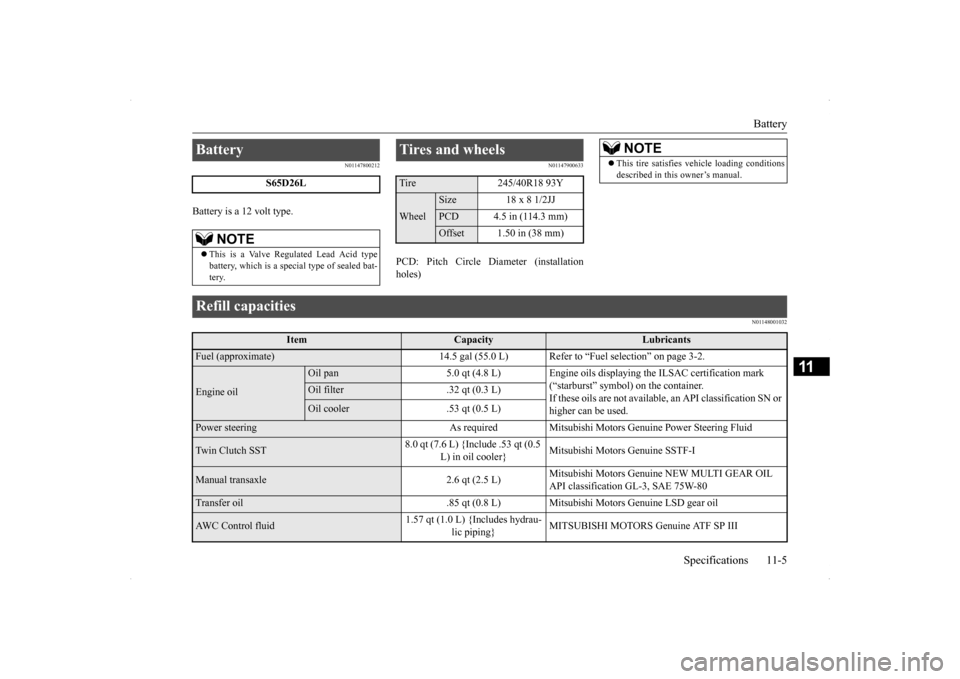
Battery
Specifications 11-5
11
N01147800212
Battery is a 12 volt type.
N01147900633
PCD: Pitch Circle Diameter (installation holes)
N01148001032
Battery
S65D26L
NOTE
This is a Valve Regulated Lead Acid type battery, which is a special type of sealed bat- tery.
Tires and wheels Tire 245/40R18 93YWheel
Size 18 x 8 1/2JJPCD 4.5 in (114.3 mm)Offset 1.50 in (38 mm)
NOTE
This tire satisfies vehicle loading conditions described in this owner’s manual.
Refill capacities
Item
Capacity
Lubricants
Fuel (approximate) 14.5 gal (55.0 L) Refer
to “Fuel selection” on page 3-2.
Engine oil
Oil pan 5.0 qt (4.8 L) Engine oils displaying the ILSAC certification mark
(“starburst” symbol) on the container.If these oils are not available,
an API classification SN or
higher can be used.
Oil filter .32 qt (0.3 L)Oil cooler .53 qt (0.5 L)
Power steering As required Mitsubishi
Motors Genuine Power Steering Fluid
Twin Clutch SST
8.0 qt (7.6 L) {Include .53 qt (0.5
L) in oil cooler}
Mitsubishi Motors Genuine SSTF-I
Manual transaxle 2.6 qt (2.5 L)
Mitsubishi Motors Genuine NEW MULTI GEAR OIL API classification GL-3, SAE 75W-80
Transfer oil .85 qt (0.8 L) Mitsubishi Motors Genuine LSD gear oilAWC Control fluid
1.57 qt (1.0 L) {Includes hydrau-
lic piping}
MITSUBISHI MOTORS Genuine ATF SP III
BK0200800US.bo
ok 5 ページ 2013年2月14日 木曜日 午後2時28分