tire type MITSUBISHI LANCER EVOLUTION 2014 10.G Owners Manual
[x] Cancel search | Manufacturer: MITSUBISHI, Model Year: 2014, Model line: LANCER EVOLUTION, Model: MITSUBISHI LANCER EVOLUTION 2014 10.GPages: 338, PDF Size: 40.99 MB
Page 37 of 338
Child restraint systems 4-12 Seat and restraint systems
4
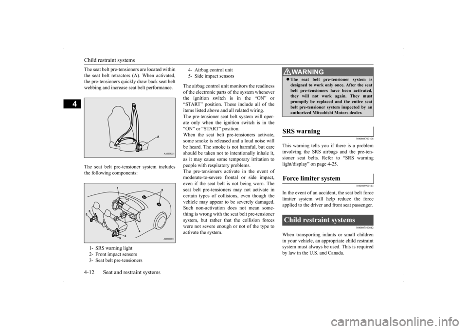
The seat belt pre-tensioners are located within the seat belt retractors (A). When activated, the pre-tensioners quickly draw back seat belt webbing and increase seat belt performance. The seat belt pre-tensioner system includes the following components:
The airbag control unit monitors the readiness of the electronic parts of the system whenever the ignition switch is in the “ON” or “START” position. These include all of theitems listed above and all related wiring. The pre-tensioner seat belt system will oper- ate only when the ignition switch is in the“ON” or “START” position.When the seat belt pre-tensioners activate, some smoke is released and a loud noise will be heard. The smoke is not harmful, but careshould be taken not to intentionally inhale it, as it may cause some temporary irritation to people with respiratory problems.The pre-tensioners activate in the event of moderate-to-severe frontal or side impact, even if the seat belt is not being worn. Theseat belt pre-tensioners may not activate in certain types of collisions, even though the vehicle may appear to be severely damaged.Such non-activation does not mean some- thing is wrong with the seat belt pre-tensioner system, but rather that the collision forceswere not severe enough or not of the type to activate the system.
N00408700108
This warning tells you if there is a probleminvolving the SRS airbags and the pre-ten- sioner seat belts. Refer to “SRS warninglight/display” on page 4-25.
N00408900113
In the event of an accident, the seat belt forcelimiter system will help reduce the force applied to the driver and front seat passenger.
N00407100642
When transporting infants or small childrenin your vehicle, an appropriate child restraint system must always be used. This is requiredby law in the U.S. and Canada.
1- SRS warning light 2- Front impact sensors 3- Seat belt pre-tensioners
4- Airbag control unit 5- Side impact sensors
WA R N I N G The seat belt pre-tensioner system is designed to work only once. After the seat belt pre-tensioners have been activated, they will not work again. They must promptly be replaced and the entire seatbelt pre-tensioner system inspected by an authorized Mitsubishi Motors dealer.
SRS warning Force limiter system Child restraint systems
BK0200800US.bo
ok 12 ページ 2013年2月14日 木曜日 午後2時28分
Page 45 of 338
Supplemental Restraint System (SRS) - airbag 4-20 Seat and restraint systems
4
Regularly check your seat belt buckles and their release mechanisms for positive engage- ment and release of the latch plate. Check the retractors for automatic locking when in theAutomatic Locking Retractor function. The entire seat belt assembly should be replaced if the webbing shows any obvious cuts, tears, increase in thickness in any sec-tion of the webbing from broken fibers, or severe fading from sunlight. All of these con- ditions indicate a weakening of the belt,which may adversely affect seat belt perfor-mance in an accident.
N00407701746
This vehicle is equipped with a SupplementalRestraint System (SRS), which includes air-bags for the driver and passengers.
The SRS front airbags are designed to supple- ment the primary protection of the driver and front passenger seat belt systems by provid- ing those occupants with protection againsthead and chest injuries in certain moderate to severe frontal collisions. The SRS front airbags, together with sensorsat the front of the vehicle and sensors attached to the front seats, form an advanced airbag system. The SRS driver’s knee airbag is designed to supplement the primary protection of thedriver’s seat belt system. It can reduce the forward movement of the driver’s lower legs and provide increased overall body protectionin certain moderate to severe frontal colli- sions. The SRS side airbags and the curtain airbags are also designed to supplement the seat belts.The SRS side airbags provide the driver and front passenger with protection against chest injuries by deploying the bag on the sideimpacted in moderate to severe side impact collisions. The SRS curtain airbags provide the driver and passengers on the front seatand rear outboard seat with protection against head injuries by deploying a bag on the side impacted in moderate to severe side impactcollisions.
The SRS airbags are NOT
a substitute for use
of the seat belts. For maximum protection in all types of accidents, seat belts must ALWAYS be worn by everyone who drives orrides in this vehicle (with infants and small children in an appropriate child restraint sys- tem in the rear seat, and older children buck-led in the rear seat). Refer to “Child restraint systems” on page 4-12.
WA R N I N G Do not attempt to repair or replace any part of the seat belt assemblies. This work should be done by an authorized Mitsubishi Motors dealer. Failure to havean authorized Mitsubishi Motors dealer perform the work could reduce the effec- tiveness of the belts and could result in aserious injury or death in an accident.
Supplemental Restraint Sys- tem (SRS) - airbag
WA R N I N G IT IS VERY IMPORTANT TO ALWAYS WEAR YOUR SEAT BELT PROPERLY EVEN WITH AN AIRBAG.• Seat belts help keep the driver and pas-sengers properly positioned. This reduces the risk of injury in all collisions,and reduces the risk of serious injuries or death when the airbags inflate. During sudden braking just before a col-lision, an unrestrained or improperly restrained driver or passengers can move forward into direct contact with, orwithin close proximity to, the airbag when it begins to inflate. The beginning stage of airbag inflation isthe most forceful and can cause serious injuries or death if the occupant comes in contact with the airbag at this time. • Seat belts reduce the risk of injury inrollovers, rear impact collisions, and in lower-speed frontal collisions, because the airbags are not designed to inflate inthose situations.
BK0200800US.bo
ok 20 ページ 2013年2月14日 木曜日 午後2時28分
Page 64 of 338
Break-in period
Features and controls 5-3
5
N00508700301
For future performance and economy of your vehicle, we recommend that you carry out thefollowing precautions. Avoid revving the engine. Do not exceed 5,000 rpm for the first 600 miles (1,000 km). Avoid rough driving such as fast starts, prolonged high-speed driving and rough shifting for the first 300 miles (500 km). The high-performance brake pads on your vehicle require a short break-in period. Avoid hard braking fo
r the first 300 miles
(500 km) to prevent future abnormalbrake noise and vibration from your vehi- cle’s brake pads. The standard-equipment tires use a high- grip compound. Thus drive with extra care for the first 200 miles (300 km). Do not overload the vehicle. Observe the seating capacity (See “Cargo loads pre- cautions” on page 6-10). Do not use this vehicle for trailer towing.
N00508800588
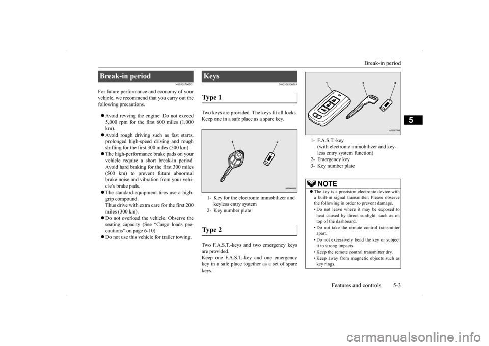
Two keys are provided. The keys fit all locks. Keep one in a safe place as a spare key. Two F.A.S.T.-keys and two emergency keys are provided.Keep one F.A.S.T.-key and one emergency key in a safe place together as a set of spare keys.
Break-in period
Keys Type 1 1- Key for the electronic immobilizer and
keyless entry system
2- Key number plateType 2
1- F.A.S.T.-key
(with electronic immobilizer and key- less entry system function)
2- Emergency key3- Key number plate
NOTE
The key is a precision electronic device with a built-in signal transmitter. Please observe the following in order to prevent damage. • Do not leave where it may be exposed to heat caused by direct sunlight, such as on top of the dashboard. • Do not take the remote control transmitter apart. • Do not excessively bend the key or subject it to strong impacts. • Keep the remote control transmitter dry. • Keep away from magnetic objects such as key rings.
BK0200800US.bo
ok 3 ページ 2013年2月14日 木曜日 午後2時28分
Page 131 of 338
All-wheel drive system 5-70 Features and controls
5
Refer to “Engine malfunction indicator (“SERVICE ENGINE SOON” or “Check engine light”)” on page 5-122 and follow the appropriate measures. A safety device in the Twin Clutch SST has been activated due to a possible malfunctionin the Twin Clutch SST. Refer to “If the gearshift lever position dis- play is not showing” on page 5-60 and follow the appropriate measures. A safety device in the Twin Clutch SST has been activated due to a possible malfunctionin the Twin Clutch SST or in the engine elec- tronic control module. Perform the following procedure.1. Park your vehicle in a safe place and stop the engine.2. Restart the engine. If the vehicle moves and accelerates normally after this procedure is
performed, there is no
malfunction.
However, if the vehicle does not move or accelerate normally, or if this problem occurs repeatedly, have the vehicle checked by an authorized Mitsubishi Motors dealer or arepair facility of your choice as soon as possi- ble.
N00516400020
All-wheel drive vehicles are propelled by engine power distributed constantly andappropriately to all four wheels. Not only does this ensure enhanced handling on dry, paved roads but also permits better traction when driving on slippery, wet orsnow-covered roads and when moving out of mud. These vehicles, however, are not designedfor off-road use, and are unsuitable for driving on bumpy ground that may cause excessive strain.
All-wheel drive vehicles
should be driven only under the same condi-
tions as are suitable for ordinary front-wheel drive vehicles.
N00530800174
Since driving torque can
be applied to all four
wheels, the performance of the vehicle whenoperating in all-wheel drive is greatly affected by the condition of the tires. Pay close attention to the tires. Install specified tires on all wheels. Refer to “Tires and wheels” on page 11-5. Be sure to fit all four tires and wheels of the same size and type. When replacement of any of the tires orwheels is necessary, replace all of them. All tires should be rotated whenever the wear difference between the front and reartires is recognizable.
Good vehicle performance cannot be expected if there is a difference in wear between tires. Refer to “Tire rotation” onpage 9-18. Check the tire inflation pressure regularly.
When the gearshift lever position display is not showing When warning display is showing or when no warning is showing in the multi- information display
CAUTION When the Twin Clutch SST fluid tempera- ture is high, the engine idle speed when the vehicle is stopped may increase or the vehi- cle will have a weak tendency to creep.After that, if the Twin Clutch SST fluid tem- perature rises even higher, the warning display will appear.
All-wheel drive system
Cautions on handling of all- wheel drive vehicles Tires and wheels
BK0200800US.bo
ok 70 ページ 2013年2月14日 木曜日 午後2時28分
Page 132 of 338
S-AWC (Super-All Wheel Control)
Features and controls 5-71
5
N00541300036
S-AWC is an integrated vehicle dynamics control system that helps enhance drivingperformance, cornering performance, and vehicle stability over a wide range of driving conditions through integrated management ofthe ACD, the AYC, the anti-lock braking sys- tem, and the active stability control (ASC).
Please read this section in conjunction with the following sections. ACD (Active center differential system)
P.5-71AYC (Active yaw control system)
P.5-72
Anti-lock braking system
P.5-74
Active stability control (ASC)
P.5-76
N00541400011
The ACD is a system
that improves accelera-
tion performance and straight-ahead stabilityby regulating the differential limiting action
CAUTION Always use tires of the same size, same type, and same brand, and which have no wear dif- ferences. Using tires that differ in size, type, brands or the degree of wear, will increase the differential oil temperature, resulting inpossible damage to the driving system. Fur- ther, the drive train will be subjected to excessive loading, possibly leading to oilleakage, component seizure, or other serious problems.
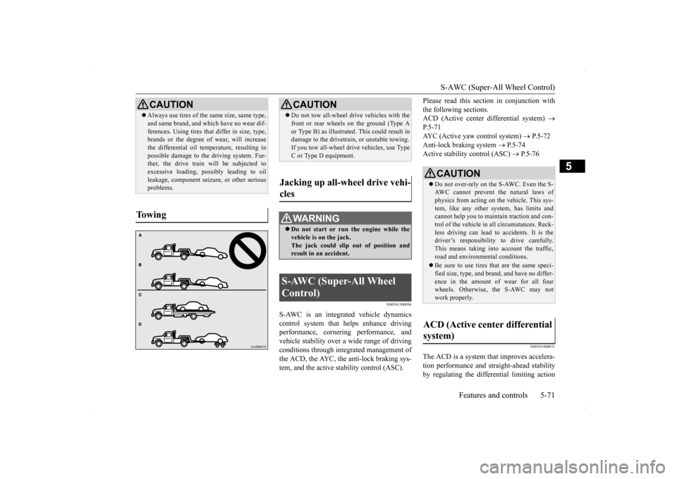
To w i n g
CAUTION Do not tow all-wheel dr
ive vehicles with the
front or rear wheels on the ground (Type A or Type B) as illustrated. This could result in damage to the drivetrain, or unstable towing. If you tow all-wheel drive vehicles, use TypeC or Type D equipment.
Jacking up all-wheel drive vehi- cles
WA R N I N G Do not start or run the engine while the vehicle is on the jack. The jack could slip out of position andresult in an accident.
S-AWC (Super-All Wheel Control)
CAUTION Do not over-rely on the S-AWC. Even the S- AWC cannot prevent the natural laws ofphysics from acting on the vehicle. This sys- tem, like any other system, has limits and cannot help you to maintain traction and con-trol of the vehicle in all circumstances. Reck- less driving can lead to accidents. It is the driver’s responsibility to drive carefully.This means taking into account the traffic, road and environmental conditions. Be sure to use tires that are the same speci- fied size, type, and brand, and have no differ- ence in the amount of wear for all fourwheels. Otherwise,
the S-AWC may not
work properly.
ACD (Active center differential system)
BK0200800US.bo
ok 71 ページ 2013年2月14日 木曜日 午後2時28分
Page 136 of 338
Anti-lock braking system
Features and controls 5-75
5
When the anti-lock braking system is in use, you may feel the brake pedal pulsa- tion and the vibrations of the vehicle body and steering wheel. It may also feel as ifthe pedal resists being pressed. In this situation, simply hold the brake pedal down firmly. Do not pump thebrake, which will result in reduced braking performance. An operation noise is emitted from the engine compartment or feel a shock fromthe brake pedal when start driving imme- diately after starting the engine. These are normal sound or operation that the anti-lock braking system makes when per- forming a self-check. It does not indicate a malfunction. The anti-lock braking system can be used after the vehicle has reached a speed over approximately 6 mph (10 km/h). It stopsworking when the vehicle slows below approximately 3 mph (5 km/h).
N00531600632
Warning light Warning display If there is a malfunction in the system, the anti-lock braking system warning light willcome on and the warning display will appear on the information screen in the multi-infor- mation display.Under normal conditions,
the anti-lock brak-
ing system warning light only comes on when the ignition switch is turned to the “ON”position and goes off a few seconds later.
N00531700561
Avoid hard braking and high-speed driving. Stop the vehicle in a safe place. Test the system by restarting the engine anddriving at a speed of about 12 mph (20 km/h) or higher. If the warning light / display then remain offduring driving, there is no abnormal condi- tion.
CAUTION The anti-lock braking system cannot prevent accidents. It is your responsibility to take safety precautions and to drive carefully. To prevent failure of the anti-lock braking system, be sure all 4 wheels and tires are the same size and the same type.
Do not install any aftermarket limited-slip differential (LSD) on yo
ur vehicle. The anti-
lock braking system may stop functioning properly.
Anti-lock braking system warn- ing light / display
CAUTION
CAUTION Any of the following indicates that the anti- lock braking system is not functioning and only the standard brak
e system is working.
(The standard brake system is functioning normally.) If this happens, take your vehicleto an authorized Mitsubishi Motors dealer or a repair facility of your choice.• When the ignition switch is in the “ON”position, the warning light does not come on or it remains on and does not go off.• The warning light comes on while driving.• The warning display appears while driving.
If the warning light / display comes on while driving If only the anti-lock braking sys- tem warning light / display comes on
BK0200800US.bo
ok 75 ページ 2013年2月14日 木曜日 午後2時28分
Page 138 of 338
Active stability control (ASC) Features and controls 5-77
5
N00559200021
On slippery surfaces, the traction control function prevents the drive wheels from spin-ning excessive, thus helping the vehicle to start moving from a stopped condition. It also provides sufficient driving force and steeringperformance as the vehicle turns while press- ing the acceleration pedal.
N00546800010
The skid control function is designed to help the driver maintain control of the vehicle onslippery roads or during rapid steering
maneuvers. It works by controlling the engine output and the brake on each wheel.
N00559400209
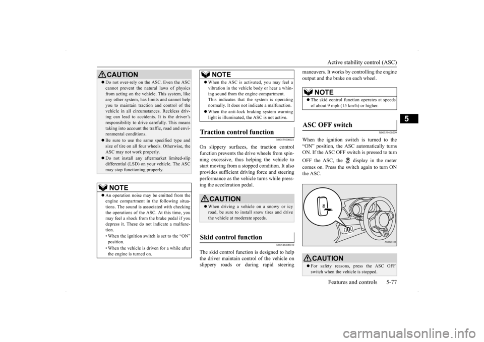
When the ignition switch is turned to the “ON” position, the ASC automatically turns ON. If the ASC OFF switch is pressed to turn OFF the ASC, the display in the meter comes on. Press the switch again to turn ON the ASC.
CAUTION Do not over-rely on the ASC. Even the ASC cannot prevent the natural laws of physics from acting on the vehicl
e. This system, like
any other system, has limits and cannot help you to maintain traction and control of thevehicle in all circumstances. Reckless driv- ing can lead to accidents. It is the driver’s responsibility to drive carefully. This meanstaking into account the traffic, road and envi- ronmental conditions. Be sure to use the same specified type and size of tire on all four wheels. Otherwise, the ASC may not work properly. Do not install any aftermarket limited-slip differential (LSD) on your vehicle. The ASCmay stop functioning properly.NOTE
An operation noise may be emitted from the engine compartment in the following situa-tions. The sound is associated with checking the operations of the ASC. At this time, you may feel a shock from the brake pedal if youdepress it. These do not indicate a malfunc- tion. • When the ignition switch is set to the “ON” position. • When the vehicle is driven for a while after the engine is turned on.
When the ASC is activated, you may feel a vibration in the vehicle body or hear a whin- ing sound from the engine compartment. This indicates that the system is operating normally. It does not indicate a malfunction. When the anti-lock braking system warning light is illuminated, the ASC is not active.
Traction control function
CAUTION When driving a vehicle on a snowy or icy road, be sure to install snow tires and drivethe vehicle at moderate speeds.
Skid control function
NOTE
NOTE
The skid control function operates at speeds of about 9 mph (15 km/h) or higher.
ASC OFF switch
CAUTION For safety reasons, press the ASC OFF switch when the vehicle is stopped.
BK0200800US.bo
ok 77 ページ 2013年2月14日 木曜日 午後2時28分
Page 150 of 338
Instrument cluster
Features and controls 5-89
5
N00533001259
Your tire pressure monitoring system oper- ates on a radio frequency subject to Federal Communications Commission (FCC) Rules(For vehicles sold in U.S.A.) and Industry Canada Rules (For vehicles sold in Canada). This device complies
with Part 15 of FCC
Rules and Industry Canada licence-exempt RSS standard(s). Operation is subject to the following two con-ditions. This device may not cause harmful inter- ference. This device must accept any interference received, including interference that may cause undesired operation.
N00519000317 N00519100220
The speedometer shows the vehicle speed in miles per hour (mph) or kilometers per hour (km/h).
N00519200205
The tachometer shows engine revolutions perminute. This allows the driver to determinethe most efficient shift position (manual transaxle) or (Twin Clutch SST) and engine speed combinations.
CAUTION The use of non-genuine wheels will prevent the proper fit of the tire inflation pressure sensors, resulting in air leakage or damage to the sensors.
General information
CAUTION Changes or modifications not expressly approved by the manufacturer for compli- ance could void the user’s authority to oper- ate the equipment.
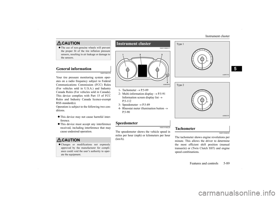
Instrument cluster 1- Tachometer
P.5-89
2- Multi-information display
P.5-91
Information screen display list
P.5-112
3- Speedometer
P.5-89
4- Rheostat meter illumination button
P.5-90
Speedometer
Tachometer Type 1Type 2
BK0200800US.bo
ok 89 ページ 2013年2月14日 木曜日 午後2時28分
Page 172 of 338
Indicator light, warning light, an
d information screen display list Features and controls 5-111
5
N00557700019 N00557800212
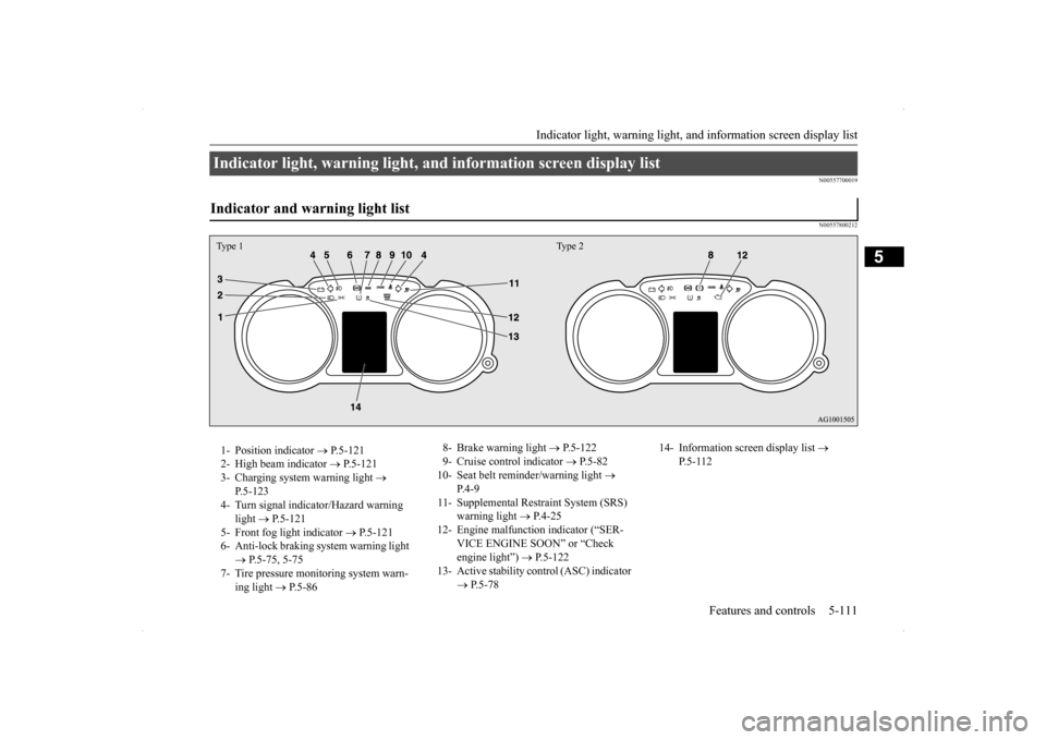
Indicator light, warning light, and information screen display list Indicator and warning light list Type 1 Type 21- Position indicator
P.5-121
2- High beam indicator
P.5-121
3- Charging system warning light
P.5-123
4- Turn signal indicator/Hazard warning
light
P.5-121
5- Front fog light indicator
P.5-121
6- Anti-lock braking system warning light
P.5-75, 5-75
7- Tire pressure monitoring system warn-
ing light
P.5-86
8- Brake warning light
P.5-122
9- Cruise control indicator
P.5-82
10- Seat belt reminder/warning light
P.4-9
11- Supplemental Restraint System (SRS)
warning light
P.4-25
12- Engine malfunction indicator (“SER-
VICE ENGINE SOON” or “Check engine light”)
P.5-122
13- Active stability control (ASC) indicator
P.5-78
14- Information screen display list
P.5-112
BK0200800US.book
111 ページ 2013年2月14日 木曜日 午後2時28分
Page 268 of 338
Towing
For emergencies 8-11
8
N00850000117
Reverse the removing procedure when stor- ing the flat tire or spare tire, jack, bar and wheel nut wrench. Refer to “To remove the compact spare tire”on page 8-7 and “Tools and jack” on page 8-5.
N00837000716
If towing is necessary, we recommend you to have it done by a commercial tow truck ser-vice.
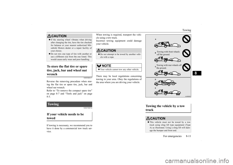
When towing is required, transport the vehi- cle using a tow truck. Incorrect towing equipment could damage your vehicle. There may be local regulations concerning towing in your area. Obey the regulations of the area where you are driving your vehicle.
If the steering wheel vibrates when driving after changing the tire, have the tire checked for balance at your nearest authorized Mit- subishi Motors dealer
or a repair facility of
your choice. Do not mix one type of tire with another or use a different size from the one listed. Thiswould cause early wear and poor handling.
To store the flat tire or spare tire, jack, bar and wheel nut wrench To w i n g If your vehicle needs to be towed
CAUTION
CAUTION Do not attempt to be towed by another vehi- cle with a rope.NOTE
Your vehicle cannot tow any other vehicle.
Towing the vehicle by a tow truck
CAUTION This vehicle must not be towed by a tow truck using sling lift type equipment (Type A) as illustrated. Using a sling lift will dam-age the bumper and front end.
Towing with front wheels off the ground. Towing with rear wheels off the ground.
BK0200800US.bo
ok 11 ページ 2013年2月14日 木曜日 午後2時28分